In the past, we explored the NEO-6M GPS module with Arduino through a few of our tutorials (see: "Comparing iPhone GPS Against NEO-6M with Arduino" and "Arduino GPS Tracker"). In this tutorial, we wanted to push the size limits of the portable GPS tracker by using a mini GPS module called the ATGM336H. The result is a pocket-sized GPS tracker with the low-profile by pairing the ATGM336H module with an Arduino Xiao microcontroller, SD Card Module, and 3.7V LiPo Battery. The prototype developed here will be an autonomous tracker that will record latitude/longitude at roughly 1-10 points per second (1Hz - 10Hz) and needs no external components to track geolocation. The prototype can fit in a users pocket and can track for several hours. We will also present a Python program that will plot the geolocation data points that the user can use to view the route tracked by the Arduino GPS datalogger system. The Python analysis demonstrates how well the ATGM336H GPS module and antenna are able to replicate the walking path of a human with great resolution and accuracy.
Read MoreIn this tutorial, a 1.54 inch e-Paper module is wired to a BLE-Nano Arduino board to communicates via SPI and display text in real time over Bluetooth. The e-Paper module here can be powered via 3.3V or 5.0V, requires very low power when refreshing (2mA-8mA), and can be completely powered off while retaining its text. An Android smartphone and the BLExAR app will be used to print text on the e-Paper display in real time, demonstrating the capabilities of electronic paper technology.
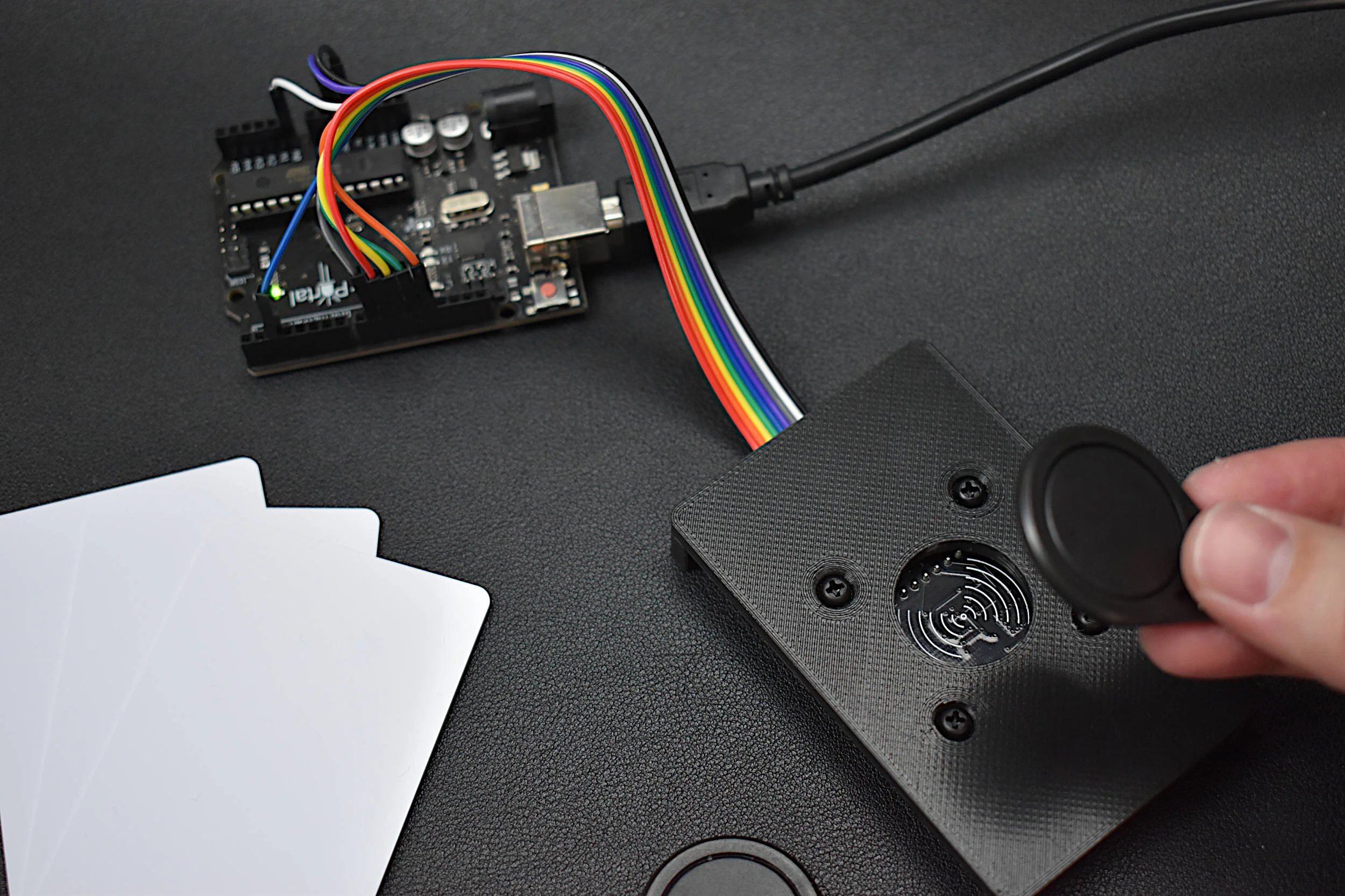
Read MoreRadio Frequency Identification, or RFID, is a widely used technology developed for storing and retriving information in radio frequency-enabled devices. Most often, RFID systems consist of one or multiple RF tags, an RF reader, and a database. In this tutorial series, passive, high frequency (13.56 MHz) RFID tags are the focus, as they are very compact, inexpensive, and require no external battery power. Using an Arduino board, a common RFID reader (MFRC522), and a few RFID tags/cards, we will be exploring methods for reading and writing RFID information in an attempt to understand the how RFID communication works and the limits of the technology.
Read MoreThis is the third tutorial in a series dedicated to exploring the Raspberry Pi Foundation's groundbreaking new microcontroller: the Raspberry Pi Pico. The first entry centered on the basic principles of interfacing with the Pico and programming with Thonny and MicroPython, while the second entry focused on emulating the Google Home and Amazon Alexa LED animations with a WS2812 RGB LED array. In this tutorial, an SSD1306 organic light emitting diode (OLED) display will be controlled using the Pico microcontroller. A MicroPython library will be used as the base class for interfacing with the SSD1306, while custom algorithms are introduced to create data displays. Additionally, a custom Python3 algorithm will be given that allows users to show a custom image on the display. Lastly, a real-time plot will be created that shows an audio signal outputted by a MEMS microphone, emulating a real-time graph display. The SSD1306 is a useful tool for smaller scale projects that require real-time data displays, control feedback, and IoT testing. The power of the Pico microcontroller makes interfacing with the SSD1306 fast and easy, which will be evident when working with the Pico and SSD1306.
Read MoreThis is the second entry into the Raspberry Pi Pico tutorial series dedicated to exploring the capabilities of the Raspberry Pi Foundation's groundbreaking new Pico microcontroller. A WS2812 RGB LED is controlled via the programmable I/O system (PIO) on the Pico microcontroller. The code and methods used to control the WS2812 are based on Raspberry Pi Pico Micropython SDK the project entitled "Using PIO to drive a set of NeoPixel Ring (WS2812 LEDs)." A state machine is used on the Pico to control the WS2812 LED array, which allows users to test a range of algorithms that affect the ring light. The light mappings will subsequently be capable of emulating the LED effects similar to those demonstrated by the Amazon Alexa or Google Home devices. A universal wiring diagram is given that allows for any number of LEDs to be wired to the Pico, which we tested up to 60 LEDs.
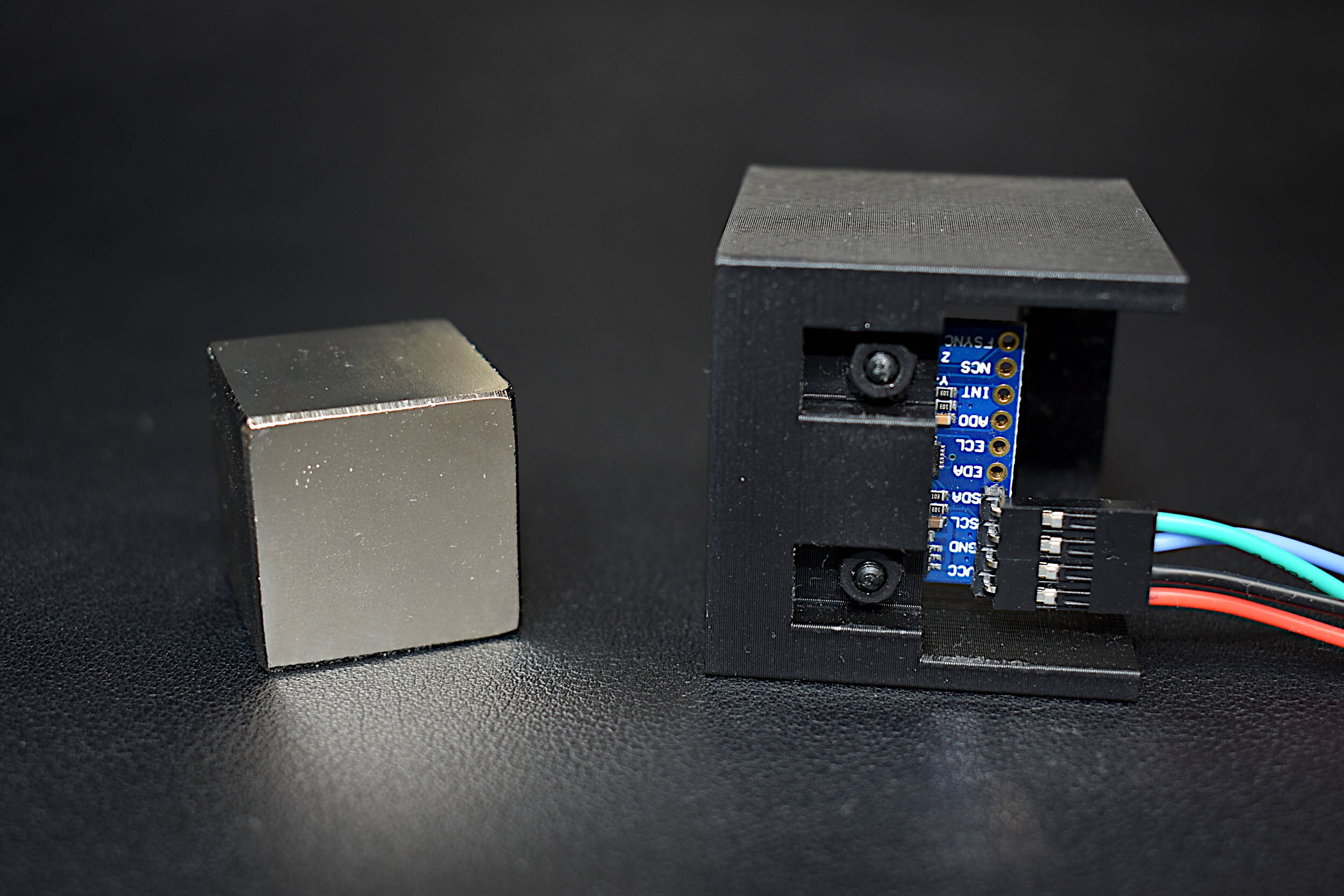
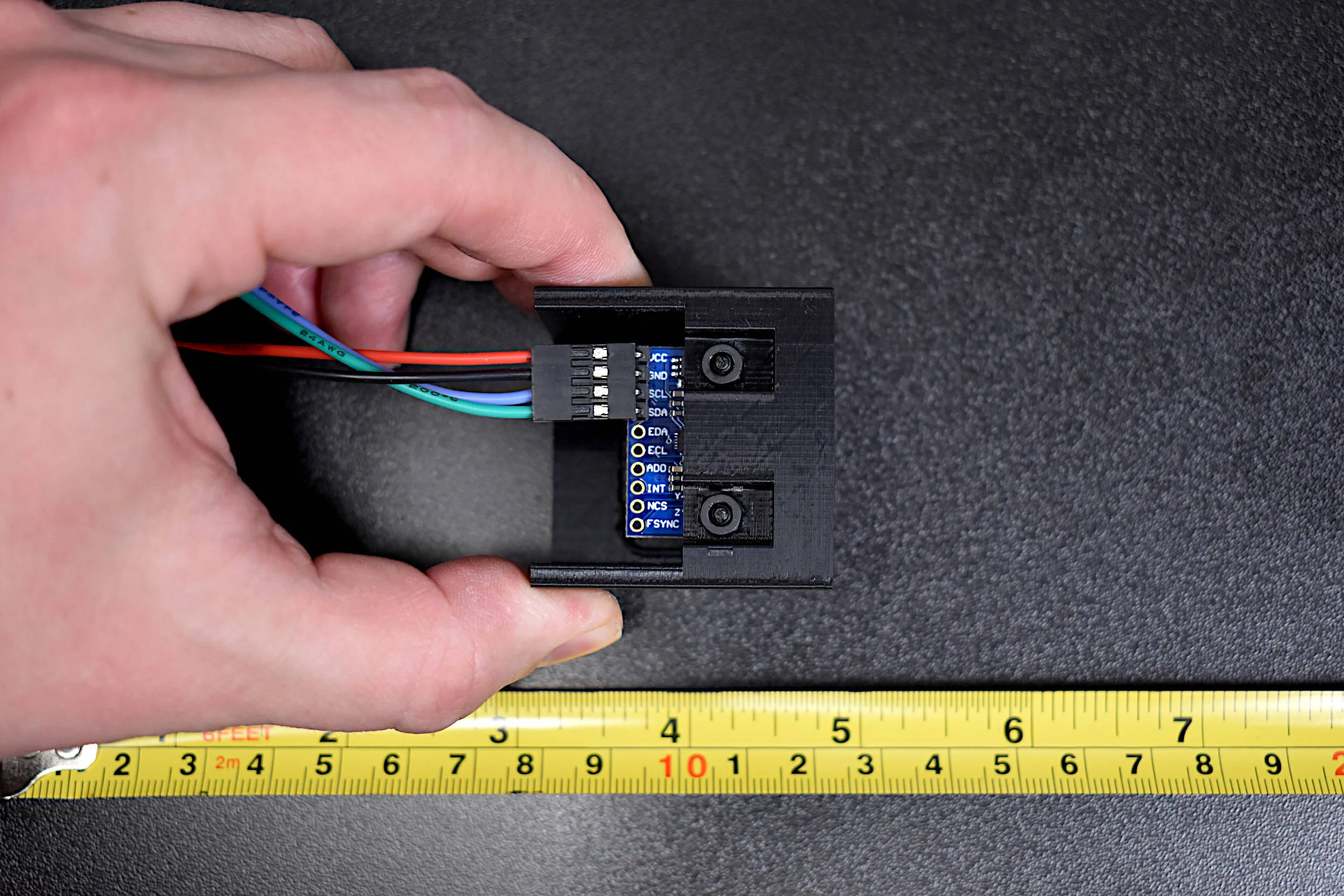
Read MoreIn this tutorial, methods for calibrating a magnetometer aboard the MPU9250 is explored using our Calibration Block. The magnetometer is calibrated by rotating the IMU 360° around each axis and calculating offsets for hard iron effects. Python is again used as the coding language on the Raspberry Pi computer in order to communicate and record data from the IMU via the I2C bus. The second half of this tutorial gives a full calibration routine for the IMU's accelerometer, gyroscope, and magnetometer. The final implementation will allow for moderate (first-order) calibration of the MPU9250 under reasonable conditions, requiring only the calibration block and IMU. Finally, the complete final code will save the coefficients for each sensor for future use in direct applications without the need for constant calibration. The use of the calibration coefficients will allow for improved estimates of orientation, displacement, vibration, and other relevant control and measurement analyses.
Read MoreThis is the second entry into the series entitled "Calibration of an Inertial Measurement Unit (IMU) with Raspberry Pi" where the gyroscope and accelerometer are calibrated using our Calibration Block. Python is used as the coding language on the Raspberry Pi to find the calibration coefficients for the two sensors. Validation methods are also used to integrate the IMU variables to test the calibration of each sensor. The gyroscope shows a fairly accurate response when calibrated and integrated, and found to be within a degree of the actual rotation test. The accelerometer was slightly less accurate, likely due to the double integration required to approximate displacement and the unbalanced table upon which the IMU was calibrated. Filtering methods are also introduced to smooth the accelerometer data for integration. The final sensor, the magnetometer (AK8963), will be calibration in the next iteration of this series.
Read MoreThe INMP441 MEMS microphone is used to record audio using a Raspberry Pi board through the inter-IC sound (I2S or I2S) bus. The I2S standard uses three wires to record data, keep track of timing (clock), and determine whether an input/output is in the left channel or right channel. First, the Raspberry Pi (RPi) needs to be prepped for I2S communication by creating/enabling an audio port in the RPi OS system. This audio port will then be used to communicate with MEMS microphones and consequently record stereo audio (one left channel, one right channel). Python iS then used to record the 2-channel audio via the pyaudio Python audio library. Finally, the audio data will be visualized and analyzed in Python with simple digital signal processing methods that include Fast Fourier Transforms (FFTs), noise subtraction, and frequency spectrum peak detection.
Read MoreCartopy is a cartographic Python library that was developed for applications in geographic data manipulation and visualization. It is the successor to the the Basemap Toolkit, which was the previous Python library used for geographic visualizations. Cartopy can be used to plot satellite data atop realistic maps, visualize city and country boundaries, track and predict movement based on geographic targeting, and a range of other applications relating to geographic-encoded data systems. In this tutorial, Anaconda 3 will be used to install Cartopy and related geographic libraries. As an introduction to the library and geographic visualizations, some simple tests will be conducted to ensure that the Cartopy library was successfully installed and is working properly. In subsequent tutorials: shapefiles will be used as boundaries, realistic city streets will be mapped, and satellite data will be analyzed.
Read MoreIn this tutorial, an ultrasonic sensor (HC-SR04) will be used in place of a radio emitter; and a plan position indicator will be constructed in Python by recording the angular movements of a servo motor. An Arduino board will both record the ranging data from the ultrasonic sensor while also controlling and outputting the angular position of the servo motor. This will permit the creation of a PPI for visualizing the position of various objects surrounding the radar system.
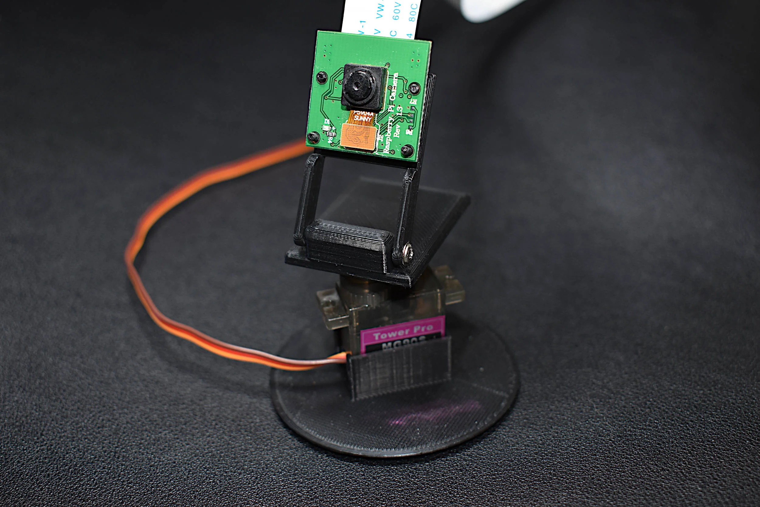
Read MoreIn this tutorial, the RPi is used to demonstrate pulse-width modulation (PWM) and apply it to servo motor control. Then, the servo is used to control the panning of a camera - which is also controlled by the native camera port on the Raspberry Pi. This tutorial is a simple introduction that can be expanded into a full 360° controllable camera project, or a project involving a robotic arm, or any project involving servo motors or PWM-controlled devices.
Read MorePython has a multitude of libraries dedicated to scraping the internet in various ways. For example, Google Trends is a product produced by Google that analyzes search history and publishes the popularity of search terms over time. One user created an algorithm to pull trend data from Google using Python in a package called pytrends. Another such library uses Python to pull stock information from Yahoo Stocks in a package called yfinance. Both of these libraries will be used to plot and compare finance and trend data over time using Python scripts. The methods outlined in this tutorial could be applied to areas in finance, data analytics, and data visualization in general.
Read MoreIn this tutorial, another method of control is introduced that involves manual control using input from the serial monitor. This means each pin can be turned on or off using the human input to the serial monitor. An RGB LED is used to demonstrate the capability of serial monitor control, where each color of the LED is controlled individually using dedicated Arduino pins.
Read MorePython’s file transfer protocol (FTP) library is used to parse weather station data from the publicly available automated surface observing system (ASOS) from the U.S.A.’s National Climatic Data Center (NCDC). Several programmatic tools available in Python are used to automate the parsing of weather data, as well as visualizing the resulting data.
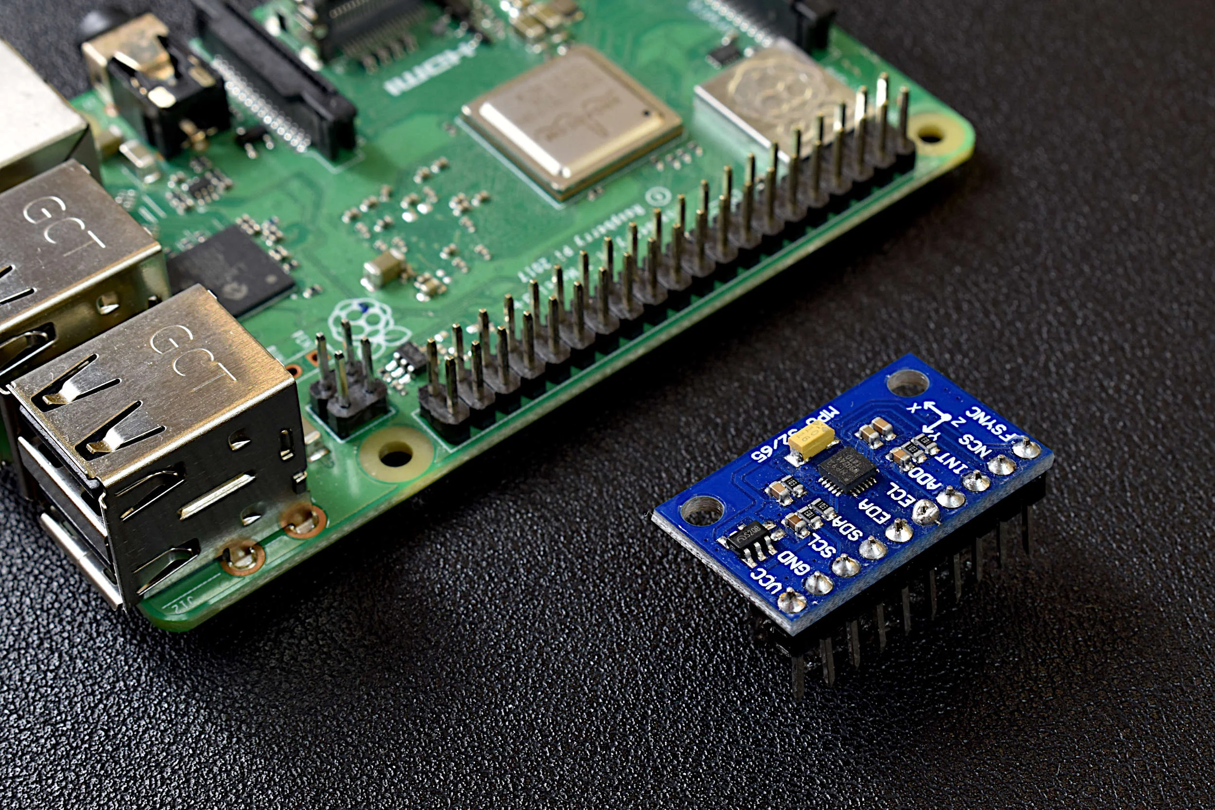
Read MoreA Raspberry Pi will be used to read the MPU9250 3-axis acceleration, 3-axis angular rotation speed, and 3-axis magnetic flux (MPU9250 product page can be found here). The output and limitations of the MPU9250 will be explored, which will help define the limitations of applications for each sensor. This is only the first entry into the MPU9250 IMU series, where in the breadth of the articles we will apply advanced techniques in Python to analyze each of the 9-axes of the IMU and develop real-world applications for the sensor, which may be useful to engineers interested in vibration analysis, navigation, vehicle control, and many other areas.
Read MoreIn this tutorial, the ATtiny85 is reintroduced, this time as a Bluetooth-enabled device. First, some of the basics of burning the bootloader to the ATtiny85 and using the Arduino board as an in-system programmer (ISP) are explored. Then, a CC2541 Bluetooth Low Energy (BLE) module is used to communicate with an iOS device using the BLExAR app. Lastly, temperature and humidity data is read by the ATtiny85 and transmitted via Bluetooth to the smartphone.
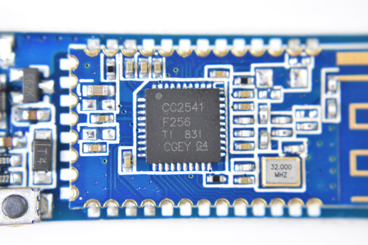
Read MoreIn this tutorial, I will dive into the variations of CC2541 BLE board such as the AT-09, MLT-BT05, HM-10, JDY-08, etc. I will use either the specific module name or a blanketed “CC2541-based module” reference to refer to the BLE modules. The general process for interfacing with each module is nearly the same, however, some particularities define how each responds and functions depending on the given firmware. I will also be using the BLExAR app for iOS to communicate with the CC2541 modules.
Read MoreLoRa modules, such as the SX1276 used in this tutorial, are widely available and relatively inexpensive, all while being fully compatible with Arduino. LoRa modules are also modular in software and hardware: transmission power is configurable, the modules can be outfitted with antennae, and transmission speed and packet information size are both modifiable. In this tutorial, an Arduino board and SX1276 modules will be used to create a network of long range (LoRa) nodes designed to communicate and transport information. The use of antennae will also help broaden the range of the nodes, and tests in New York City will help quantify the efficiency and cone of functionality for such a node in a complex environment.
Read MoreThe NEO-6 is a miniature GPS module designed by u-blox to receive updates from up to 22 satellite on 50 different channels that use trilateration to approximate fixed position of a receiver device every second (or less, for some modules). The particular module used in this tutorial, the NEO-6M, is capable of updating its position every second and communicates with an Arduino board using UART serial communication. The NEO-6M uses the National Marine Electronics Association (NMEA) protocol which provides temporal and geolocation information such as Greenwich Mean Time (GMT), latitude, longitude, altitude, and approximate course speed. The NEO-6M and Arduino board will also be paired with an SD module to create a portable logger that acts as a retrievable GPS tracker.
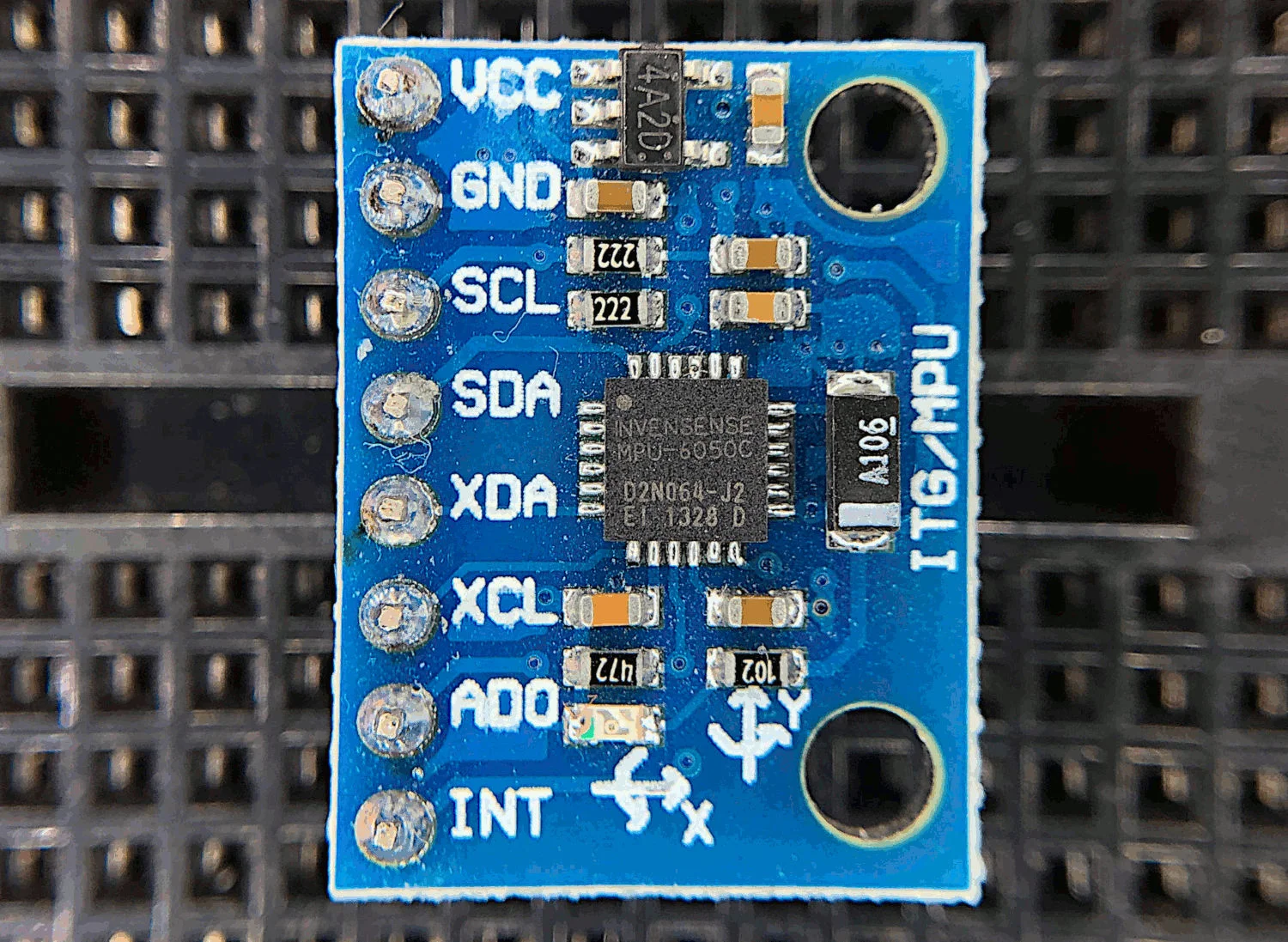
Read MoreThe MPU6050 is a 6-DoF (degree of freedom) accelerometer and gyroscope that is designed for inexpensive, small-scale, and efficient approximation of motion. Accelerometers and gyroscopes are used in smart phones for orientation detection, vibration analysis in vehicles and machines, and even camera stabilization and motion tracking. There are countless applications for accelerometers and gyroscopes, and with devices as accessible as the MPU6050, we can really test the limits of the technology.
Read More

