ATtiny85 Internet of Things Bluetooth Arduino Board
“As an Amazon Associates Program member, clicking on links may result in Maker Portal receiving a small commission that helps support future projects.”
In a previous tutorial, I demonstrated how to interface between Arduino and the ATtiny85 board. The ATtiny85 is an 8-bit AVR microcontroller and is particularly applicable for small scale projects in the Internet of Things (IoT) world due to its low power consumption and tiny 8-pin profile. The ATtiny85 will be paired with a Bluetooth module and interfaced with a smartphone to create a connected device capable of communicating information back and forth through Bluetooth Low Energy. Temperature and humidity measured by the DHT22 sensor will be read by the ATtiny85 and transmitted to the smartphone by via the Bluetooth module.
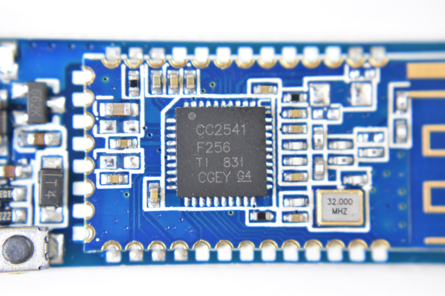
There are quite a few components used in this tutorial, all of which are listed below. The project requires an Arduino board for uploading code to the ATtiny85 microcontroller. I tested the Uno from our store and it works great. Be sure to wire the electrolytic capacitor from RESET to GND in order to successfully upload to the ATtiny85. The DHT22 sensor and CC2541 BLE module are needed to measure temperature and send data, respectively. I use the BLExAR iOS Bluetooth app to record the data sent from the ATtiny85 node.
The full parts list is given below:
ATtiny85 Microcontroller - $6.50 [Our Store]
Arduino Uno - $9.00 [Our Store]
Jumper Wires (male-to-male) - $1.50 (10 pcs) [Our Store]
Mini Breadboard - $3.00 [Our Store]
CC2541 Bluetooth Module - $8.00 [Our Store]
DHT22 Temperature and Humidity Sensor - $12.00 [Our Store]
10μF capacitor - $14.99 (500 pcs) [Amazon]
750 mAh 3.7V LiPo Battery - $19.99 (6 pcs) [Amazon]
Raspberry Pi 4 Kit - $99.99 [Amazon]

The ATtiny85 can be used as a small Arduino board that is capable of 10-bit analog-to-digital conversion, control of 6 of its digital pins, and voltage tolerances of 2.7-5.5V - all of which allow it to work under very low power electronics and internet of things applications. The microcontroller current consumption ranges from: 5mA, 1.2mA, 10uA under active/idle/power down conditions (8MHz). It also has a serial interface, which allows it to be programmed by another Arduino board, making it the perfect tiny microcontroller where larger Arduino boards may be too large.
Included in Package:
ATtiny85 AVR Microcontroller
Features of the ATtiny85:
10-bit ADC
4 Possible Analog Inputs
6 Possible Digital Pins
2.7-5.5V Tolerance
5mA, 1.2mA, 10uA Active/Idle/Power Down Current Consumption (8MHz)
Serial Interface
Interrupt Capabilities
Internal Crystal Oscillators (1MHz, 8MHz)
The ATtiny85 datasheet can be found [here].
A tutorial that uses the ATtiny85 as an Inernet of Things (IoT) board can be found here.
This is an abridged version of my previous tutorial on the ATtiny85 Arduino board. The first step is to program the ATtiny85 as an Arduino board using the ATtiny package created by David A. Mellis (GitHub). First, we need add the ATtiny package to the boards manager URL list:
https://raw.githubusercontent.com/damellis/attiny/ide-1.6.x-boards-manager/package_damellis_attiny_index.json

Step 1: Add ATtiny URL
Add ATtiny Package link [here] from David A. Mellis to File -> Preferences -> Additional Boards Manager URLs

Step 2: Download Package from Boards Manager
Tools -> Board -> Boards Manager -> Type: 'attiny' -> Install

Step 3: Upload ArduinoISP Code
File -> Examples -> ArduinoISP. Make sure line 81 is uncommented for the traditional programming using the SPI header on the Uno board. Upload to the Uno board before wiring to the ATtiny85.
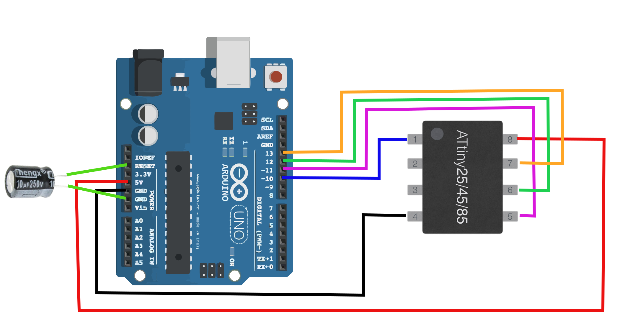
The ATtiny85 pinout is given below as a reference when wiring to the Arduino Uno board:

Step 4: Wire ATtiny85 to Arduino Uno

Step 5: Select ATtiny85 as the Board
Tools -> Board -> ATtiny25/45/85

Step 6: Verify Board Properties for ATtiny85 and 8 MHz Internal Clock

Step 7: Select Arduino as ISP Programmer

Step 8: Burn Bootloader
Now that the bootloader has been burned into the ATtiny85 board, test that simple sketches such as LED blink and analog read work as expected. Take note of the pinout diagram above for specific pin relationships and how they relate to the traditional Arduino pinouts. For the most part, they are similar in protocol, code, and function.
Once the bootloader is burned onto the ATtiny85, we keep the wiring the same and the capacitor attached, as well as the board parameters. This allows us to treat the ATtiny85 as a standard Arduino board. We code sketches and upload them the same as we would a normal Uno board. Many of the libraries are different between ATtiny85 and other boards, but assuming we stay within the bounds of the ATtiny core, we shouldn’t have an issue. Luckily, the ATtiny has serial capabilities, which we will use to communicate with the BLE module. A specific DHT22 library will be used that is compatible with the ATtiny85 board, but that will be covered in the next section. First, we must upload the appropriate code to the ATtiny85 so that we can test its communication with the BLE board and a smartphone.
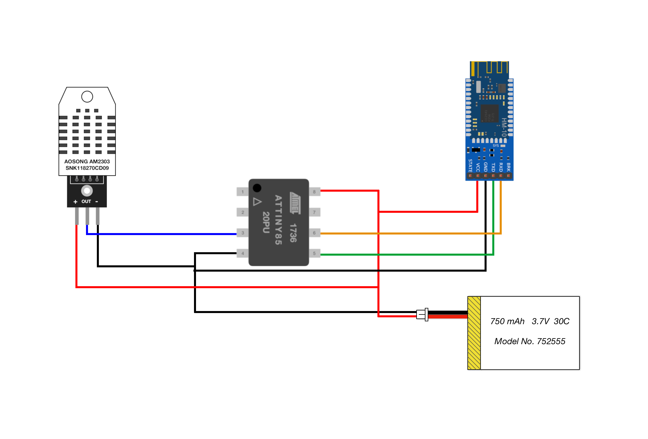
The wiring for the ATtiny85 and CC2541 Bluetooth module is given below:

The Bluetooth module TX and RX pins should be wired to digital pins 0 and 1 on the ATtiny85, which are physical pins 5 and 6 (see wiring above). The LiPo battery is wired to the VCC and GND, as expected. The Arduino code that starts the SoftwareSerial() communication between the ATtiny85 and the BLE module is given below:
// Arduino code to communicate with smartphone via BLE
#include <SoftwareSerial.h>

SoftwareSerial ble_device(0,1); // BLE TX-> ATtiny85 PB0, BLE RX-> ATtiny85 PB1

volatile int ii = 0; // integer to iterate

void setup() {
  ble_device.begin(9600); // start BEL device
  delay(500); // wait until BLE device starts

  // Once the code is uploaded once, the below can be commented out
  // (the name change only needs to occur once)
  ble_device.println("AT+NAMEATtiny85_BLE"); // change device name
  delay(500); // wait for change
  ble_device.println("AT+RESET"); // reset module to enact name change
  delay(1000); // wait for reset
}

void loop() {
  ble_device.println(ii); // send integer value to smartphone
  delay(1000);
  ii+=1; // increase integer value
}
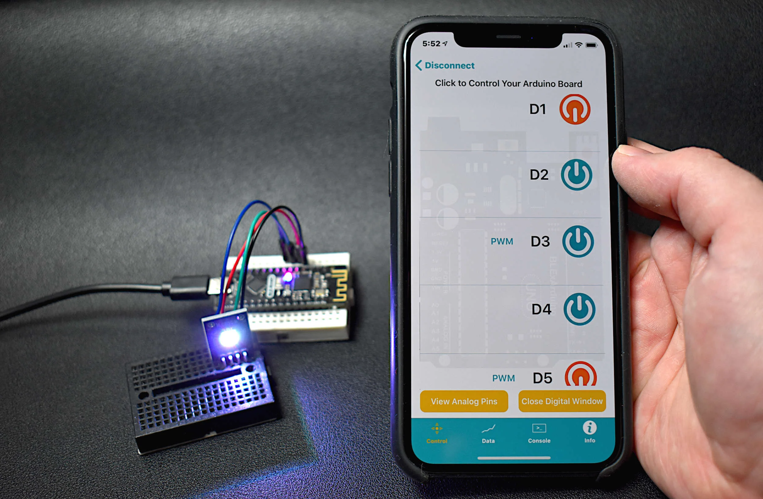
Using a BLE app on any smartphone, connect to the Bluetooth module. The code above should rename the BLE module to “ATtiny85_BLE” - which is what should show up if using the BLExAR app on an iOS device. Upon reading the serial input on an iOS device, integer values should be printed that increase by 1. If the app is updating with integer values, then the ATtiny85 Internet of Things Bluetooth board is working as expected!
In the next section, a DHT22 temperature sensor will be used to send meaningful data (temperature and humidity) to the smartphone via BLE. With the BLE module connected, we only have four pins available to interface with on the ATtiny85 board (PB2, PB3, PB4, PB5). We could use an LED as an indicator, or even drive a motor or control a relay module. For this tutorial, I will send data from a sensor and read it with a smartphone.
Using the BLExAR app, a smartphone will read temperature and humidity data sent over Bluetooth by the ATtiny85, which reads the information from the DHT22 sensor. The next step is to download the DHT22 library that interfaces with the ATtiny85 board. The library is called “TroykaDHT” it can be downloaded directly from the Arduino IDE by following these steps:
Sketch -> Include Library -> Manage Libraries
Type in “troykadht”
Install TroykaDHT by Igor Dementiev

Troyka DHT22 Library Compatible with ATtiny85
A simple software program is given below that sends temperature and humidity data to the smartphone roughly every 2 seconds. The DHT22 and ATtiny85 isn’t the most stable, so some of the sampling may change from 2-10 seconds between data points. The timestamp is added, which is just the number of seconds printed since the start of the program. By looking at the timestamp, the user can gauge roughly how often the DHT22 is capable of sending data.
// ATtiny85 DHT22 + BLE sender
#include <TroykaDHT.h>
#include <SoftwareSerial.h>

SoftwareSerial ble_device(0,1); // BLE TX-> ATtiny85 PB0, BLE RX-> ATtiny85 PB1
DHT dht(4, DHT22); // select DHT22 and comm on PB4

void setup() {
  dht.begin();
  ble_device.begin(9600); // start BLE device
  delay(500);
    // Once the code is uploaded once, the below can be commented out
  // (the name change only needs to occur once)
  ble_device.println("AT+NAMEATtiny85_BLE"); // change device name
  delay(500); // wait for change
  ble_device.println("AT+RESET"); // reset module to enact name change
  delay(1000); // wait for reset
}

void loop() {
  String ble_str = ""; // clear BLE string
  dht.read(); // read DHT22
  if (dht.getState()==DHT_OK){ // make sure the data passes
    ble_str+=String(millis()/1000.0); // timestamp since code start [seconds]
    ble_str+=","; // comma separate
    ble_str+=String(dht.getTemperatureC(),2); // add temp to string
    ble_str+=","; // comma separate
    ble_str+=String(dht.getHumidity(),2); // add humidity to string
    ble_device.println(ble_str); // send data packet
  }
  delay(2000); // wait in-between dht22 grabs
}
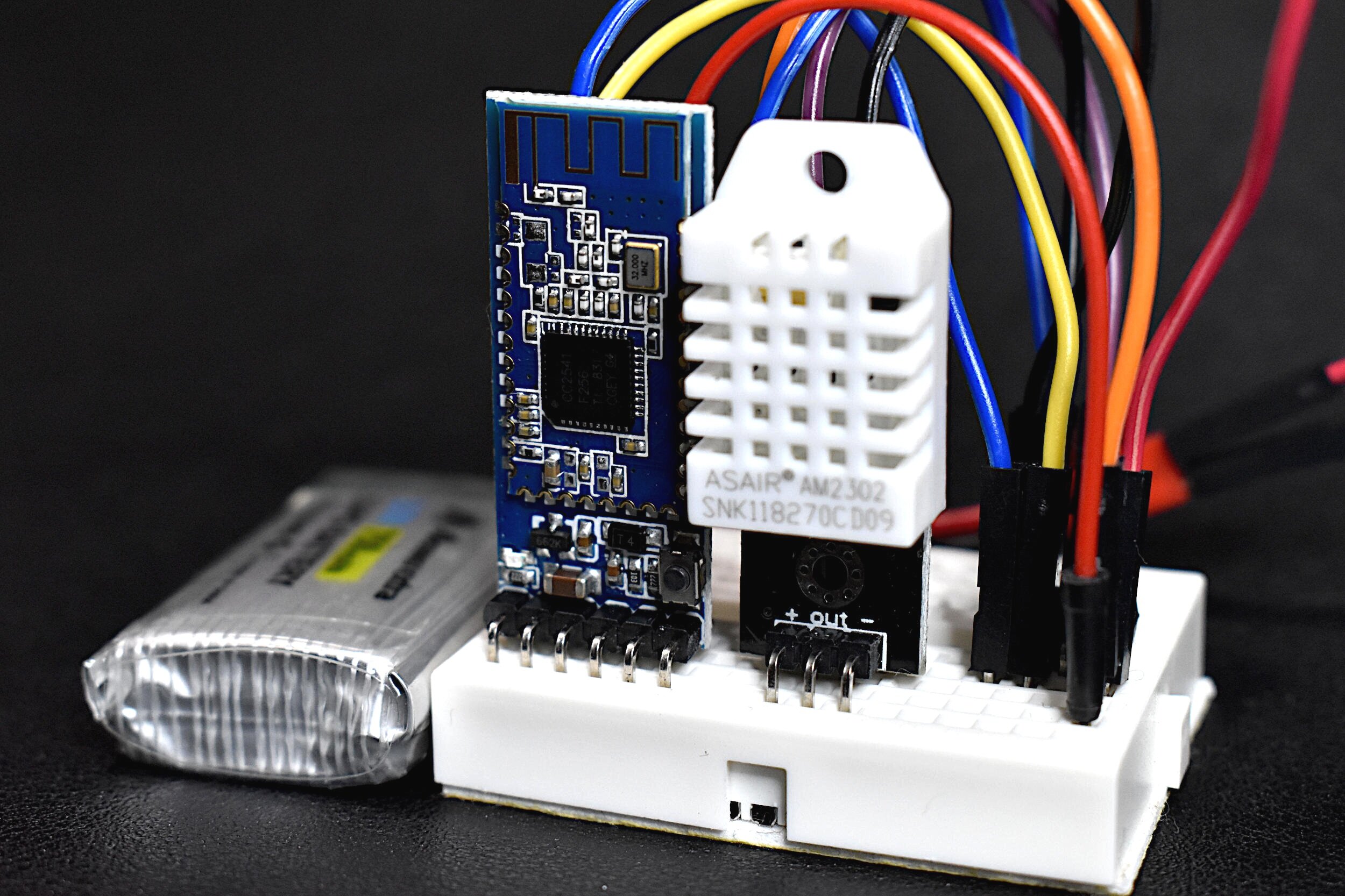
The wiring diagram for the DHT22 Bluetooth node with ATtiny85 is also given below. It’s the same wiring as in the previous section, with the addition of the DHT22 data pin wired to the ATtiny85 pin PB4 (physical pin 3).
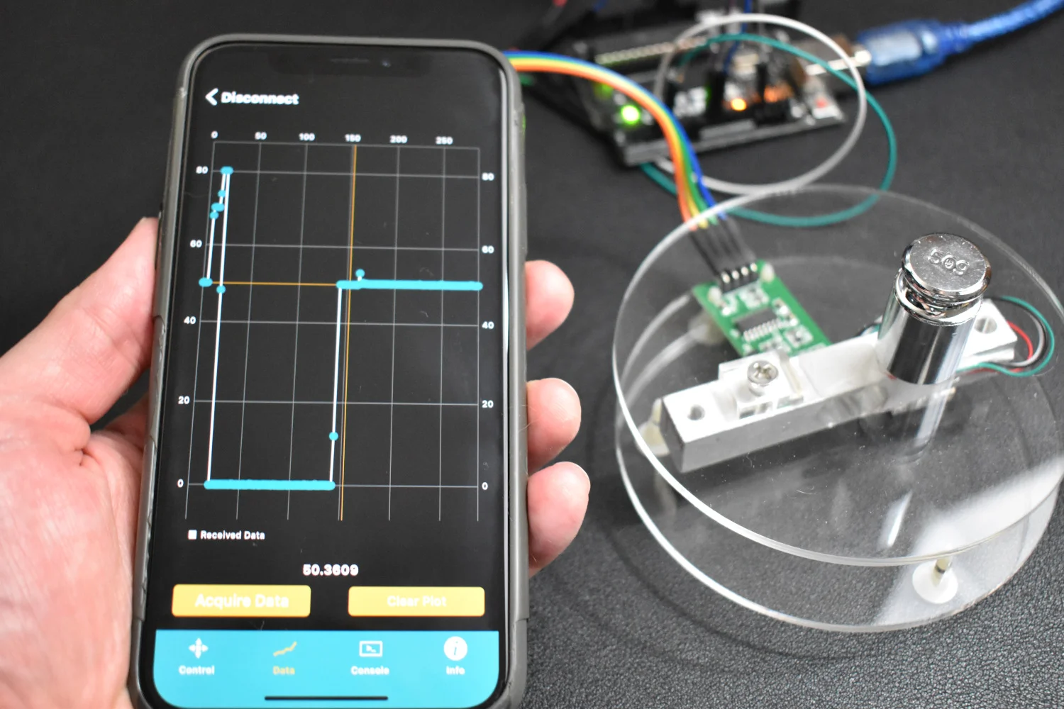
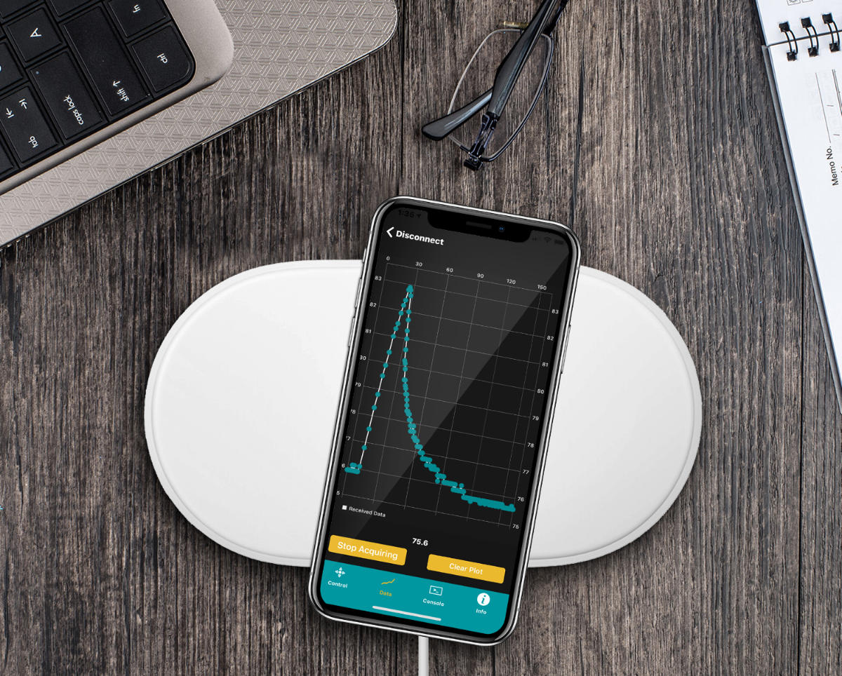
A demonstration using a smartphone and the BLExAR app is shown below, which reads the timestamp, temperature, and humidity, is shown below:

In this tutorial, the ATtiny85 was reintroduced, this time as a Bluetooth-enabled device. First, I recalled some of the basic process involved in burning the bootloader to the ATtiny85 and using the Arduino board as an in-system programmer (ISP). Then, I used a CC2541 Bluetooth Low Energy (BLE) module to communicate with an iOS device using the BLExAR app. The BLE module allowed back and forth communication between the ATtiny85 and the smartphone. This ultimately allowed us to send temperature and humidity data read by the ATtiny85 to the smartphone. This type of IoT node could be integrated into a group of nodes, perhaps with a base station receiver, which acts as a connected system, similar to the Amazon Alexa or Google Home. With a Raspberry Pi and a few ATtiny85 nodes, a similar system could be contrived. This, however, will be left for another time. And in the next section, the opposite way of communication will be explored: smartphone control of the ATtiny85. The same can be done with the standard ATmega328p board, which has more pins and flexibility compared to the ATtiny85, however the ATtiny85 is advantageous because of its small profile and low power capabilities.
See More in IoT and Arduino: