BLE Nano Arduino Board - Bluetooth Control with an iPhone (BLExAR App)

“As an Amazon Associates Program member, clicking on links may result in Maker Portal receiving a small commission that helps support future projects.”
The BLE Nano introduced here is a hybrid between an Arduino Nano and a CC2540 Bluetooth Low Energy (BLE) module. The Arduino Nano has an ATmega328P as its main microprocessor, which communicates over the serial port to send and receive Bluetooth packets from the CC2540 BLE chip. This creates a Bluetooth-enabled Arduino device - encased in a Nano-sized circuit board! Using the BLExAR iOS app, the BLE-Nano will be controlled using an iPhone. BLExAR allows users to control the pins on the Nano, which will be demonstrated by switching an RGB LED on and off, and using the PWM capabilities of the ATmega328P to dim and brighten the RGB LED. The BLE Nano is, for the most part, entirely an Arduino Nano board, with the exception that it uses its serial port to communicate with the CC2540 BLE module. The wiring, upload method, and control codes will all be given as part of this tutorial, such that users can follow along directly with the project.

This Arduino Nano board is paired with a Bluetooth Low Energy (BLE) chip that makes it both an Arduino board and a BLE-enabled device. The BLE-Nano has all the functionality of an ATmega328P microcontroller (Arduino Nano) while also having an integrated BLE chip wired to its serial pins. This means that many of your Arduino projects can be Bluetooth-enabled with just a few lines of code and the BLExAR app!
NOTE: Due to supply chain issues, the BLE-Nano has been discontinued from our store. Please see the MakerBLE Arduino Board as an improvement and alternate.
Included in the BLE-Nano Package:
1x Soldered BLE Nano Board (ATmega328P + CC2540)
1x Black Micro USB Cable
Some Features of the BLE-Nano Arduino Board:
ATmega328P Microcontroller
Arduino Nano Bootloader
Operating Voltage: 5V (Input: 5V - 12V)
16 MHz Clock Speed
Available I/O Pins: 12 Digital, 8 Analog
6 Digital PWM Pins
Current Usage: 19 mA
Profile: 48 x 19mm
Weight: 7 g
Arduino IDE Compatible
CC2540 Bluetooth Low Energy Chip
Serial Communication with Nano (pins 0/1)
2.4 GHz Bluetooth Communication
Compatible with BLExAR iOS App
Onboard Antenna
In this tutorial, the BLE Nano, RGB LED, and BLExAR app are the main components needed to follow along. A full list of components are given below:
BLE Nano - $15.00 [Our Store] (alternate: MakerBLE Board)
RGB LED - $3.00 [Our Store]
Mini Breadboard - $3.00 [Our Store]
Jumper Wires - $0.60 (4 Male-to-Male) [Our Store]
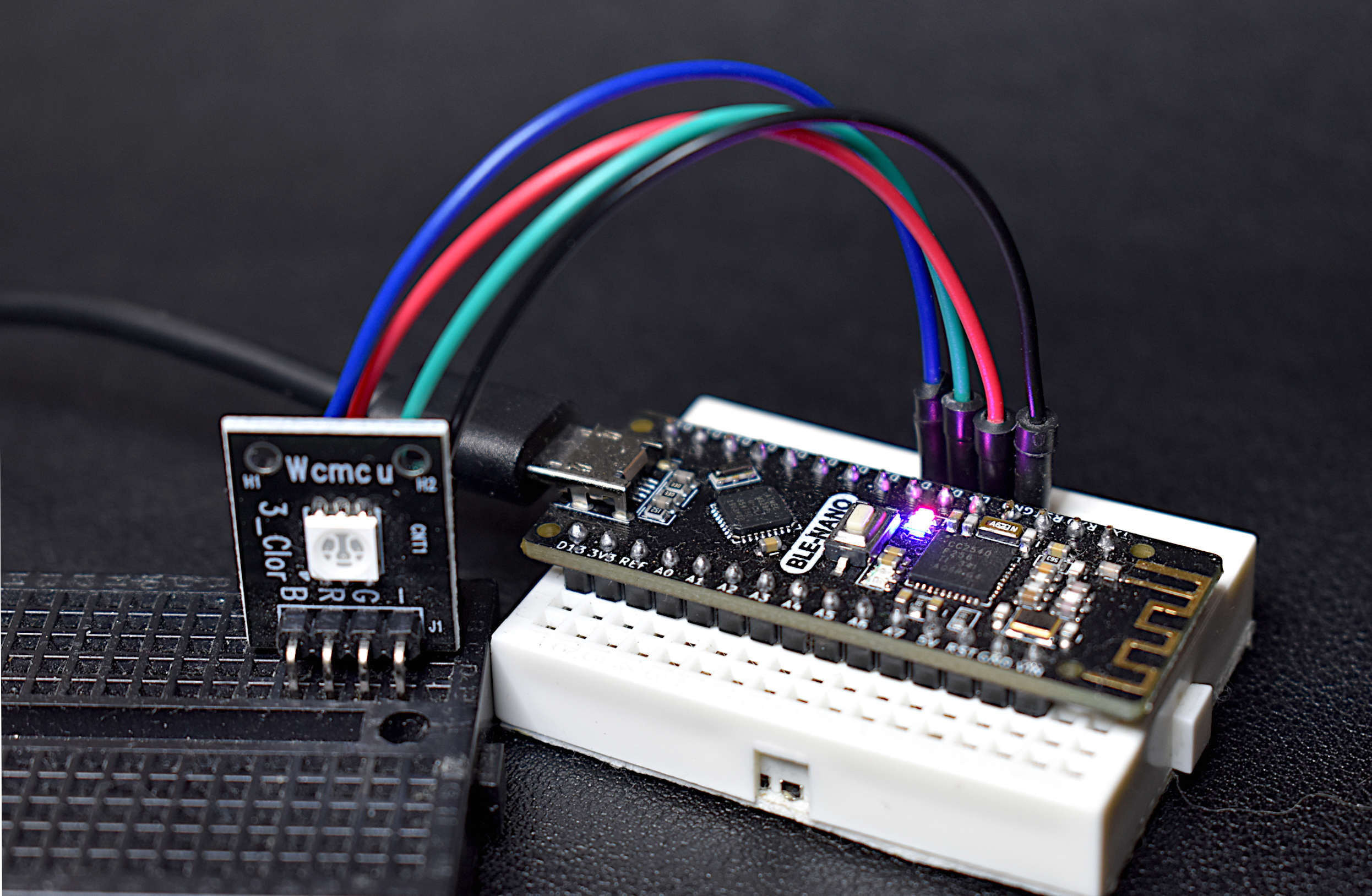
The wiring diagram and table are given below:
| BLE Nano | RGB LED |
|---|---|
| D2 | R |
| D3 | G |
| D4 | B |
| GND | - |
BLExAR iOS App

As stated in the introduction, the BLE Nano can be treated identically as an Arduino Nano board, with the small adjustment of the serial port being part of pins D0/D1. With that in mind, the RGB LED (or any sensor, indicator, motor, etc.) can be wired to pins D2 - D13, or even A0 - A7.
The BLE Nano can be treated just as an Arduino Nano: coding in the Arduino IDE is nearly identical, wiring components to it is exactly the same, and uploading code to the board can be treated just the same. The main difference is that we have to consider the serial port on pins D0/D1. This essentially means that when we write to the serial port, we are effectively writing to both the hardware serial port and the BLE serial port. This is especially important when connected to a Bluetooth device.
Before uploading any code to the BLE Nano, it must be plugged into the USB port of a computer (Raspberry Pi is used in this tutorial). Then, follow the guidelines below to ensure that the correct Arduino board is chosen, along with the respective processor (this is very important).
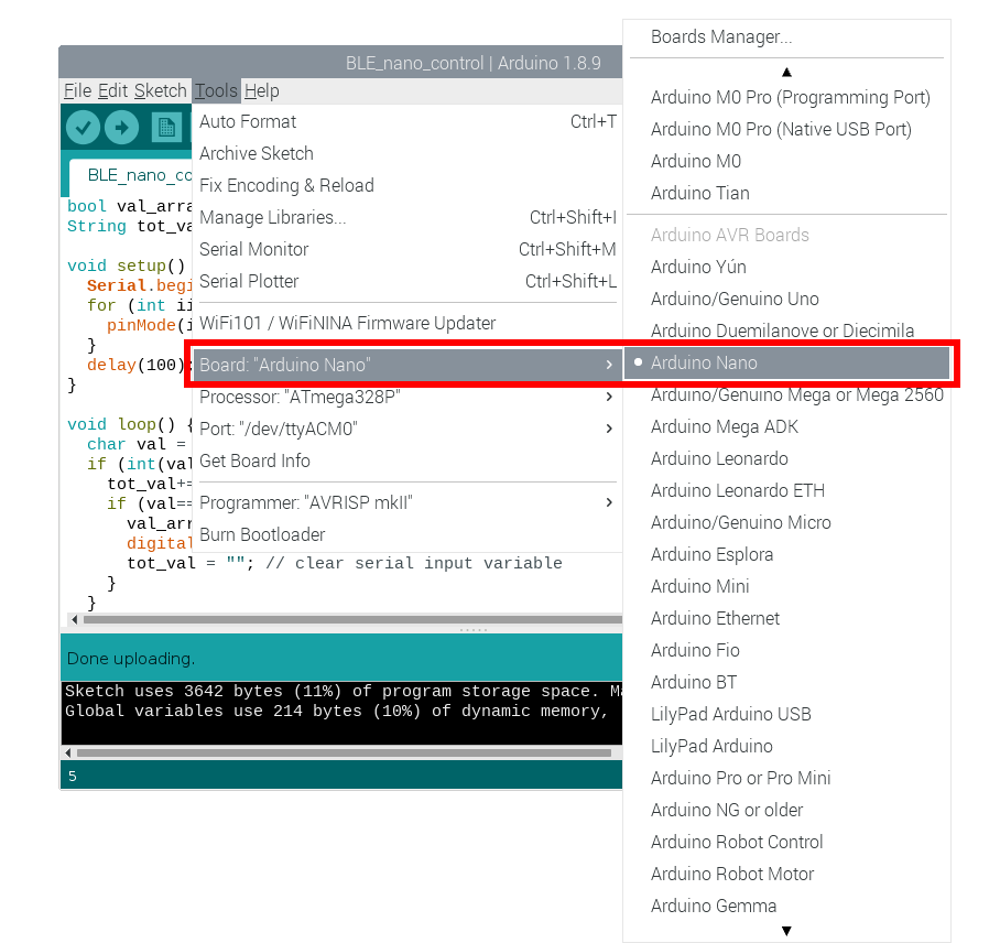
Select the Arduino Nano Board

Choose the ATmega328P with the Newest Bootloader as the Processor
The following is a simple code that loops through the RGB LED pins and turns them on/off. If the code below works, then your BLE Nano is functioning as it should. If it doesn’t work, check the wiring, and ensure the board properties are correct as per the suggestions above.
// Simple RGB LED Loop Code for BLE Nano

int rgb_led_pins[] = {2,3,4}; // pins used for RGB LED wiring

void setup() {
  for (int ii=0; ii<sizeof(rgb_led_pins)/sizeof(int);ii++){
    pinMode(rgb_led_pins[ii],OUTPUT); // set the RGB LED pins as outputs
  }
}
void loop() {
  // loop through the RGB LED pins and turn them on/off
  for (int ii=0; ii<sizeof(rgb_led_pins)/sizeof(int);ii++){
    digitalWrite(rgb_led_pins[ii], HIGH); // led high
    delay(100); // wait 100ms
    digitalWrite(rgb_led_pins[ii], LOW); // led low
    delay(100); // wait 100ms
  }
}
At this point, the BLE Nano is acting as a standard Arduino Nano board - it can look through the pins wired to the RGB LED and turn them on and off. The BLE Nano is capable of PWM, which allows the board to change the brightness of the LEDs, and it can read analog/digital pins, and it can even handle I2C device communication. In the next section, the Bluetooth Low Energy (BLE) portion of the BLE Nano will be explored - where the full breadth of the BLE Nano board will be utilized by interfacing with an iPhone BLE app, called BLExAR.
The BLE Nano uses the universal asynchronous receiver-transmitter (UART) communication protocol to communicate between the ATmega328P microcontroller and the CC2540 Bluetooth module. In short, the BLE Nano uses its serial port to send and receive information to and from other BLE-enabled devices from its CC2540 chip. Thus, in this section, the codes will be focused on serial communication with the Nano board to receive commands. The commands are received as 8-bit Unicode Transformation Format (UTF-8) characters, which we will decode as letters and numbers. These letters and numbers will help us decipher how the BLE Nano will be controlled. For example, in the code below, pins D2 - D13 are allocated as outputs on the Nano board. In the continuous loop, the BLE Nano waits for a number to be inputted (from 2-13); then, this number is taken as the pin to control. Lastly, the pin is changed based on its current state, i.e. if the pin is on, it turns off; and if the pin is off, it turns on.
The BLExAR app allows serial communication between the BLE Nano and an iOS device (iPhone or iPad). The BLExAR app was designed by our team specifically for reasons such as this - to interface between an iPhone and Arduino board.
Below is the code to control pins 2-13 on the BLE Nano using simple UTF-8 character inputs:
// Controlling the BLE Nano Arduino Board's Digital Pins
// Using the BLExAR iOS App

bool val_array[] = {0,0,0,0,0,0,0,0,0,0,0,0}; // pin booleans for on/off control
String tot_val = ""; // storage variable for serial data

void setup() {
  Serial.begin(9600); // start the comm between BLE + Arduino chips
  for (int ii = 2;ii<sizeof(val_array)/sizeof(bool)+2;ii++){
    pinMode(ii,OUTPUT); // set pins 2-13 as outputs
  }
  delay(100); // wait for outputs and serial monitor to settle
}

void loop() {
  char val = Serial.read(); // read character from BLE device (iPhone)
  if (int(val)!=-1){ // make sure it's a valid integer pin
    tot_val+=val; // if the input is over 1 character, this handles that
    if (val=='\n'){ // wait for newline
      val_array[tot_val.toInt()] = !val_array[tot_val.toInt()]; // array pin state
      digitalWrite(tot_val.toInt(),val_array[tot_val.toInt()]); // turn pin on/off
      tot_val = ""; // clear serial input variable
    }
  }
}
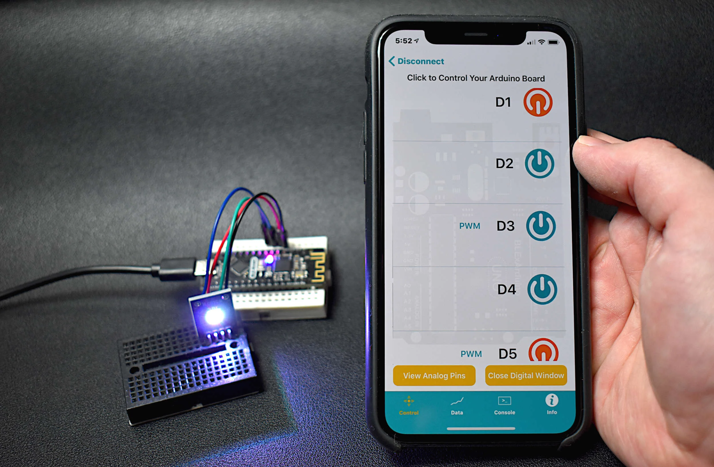
A video demonstration is given below using the code above:
Note: The BLE Nano is connected when its on-board Blue LED indicator stays lit. If it is blinking or not lit, then the BLE Nano is not connected. The BLE Nano is sensitive, so the first attempt at connecting to the CC2540 may be unsuccessful. If the BLExAR is connected, but the BLE Nano's blue indicator is off, disconnect and try connecting again.
Now, this process is not ideal for switching indicators on and off in an efficient manner. The BLExAR app has specific identifiers associated with the digital and analog pins of the ATmega328P boards. This means that the BLE Nano pins can be turned on and off by clicking the radio buttons on the ‘Control’ menu of the BLExAR app. The control code for the BLE Nano is given below:
// BLExAR BLE Nano Control Code
//
// - Control pins D2-D13/A0-A5 on the BLE Nano

String strglob= "";
String pin_num_char = "";
int pin_num = 255;
bool analog_bool = false;
bool digital_bool = false;

// the setup routine runs once when you press reset:
void setup() {
  Serial.begin(9600);
  delay(100);
}

void loop() {

  while (Serial.available()){
    char ble_char = Serial.read();
    if (ble_char == '\n'){
//      Serial.println(strglob);
      if (analog_bool){
        pinMode(pin_num,OUTPUT);
        analogWrite(pin_num,strglob.toInt());
        analog_bool = false;
        pin_num = 255;
      } else if (digital_bool){
        pinMode(pin_num,OUTPUT);
        if (strglob == "1"){
          digitalWrite(pin_num,HIGH);
        } else if (strglob == "0"){
          digitalWrite(pin_num,LOW);
          pinMode(pin_num,INPUT);
        }
        digital_bool = false;
        pin_num = 255;
      }
      pin_num = 255;
      strglob = "";
    } else {
      if (analog_bool == false and digital_bool == false) {
        if (ble_char == 'D'){
          digital_bool = true;
        } else if (ble_char == 'A'){
          analog_bool = true;
        } else {
        }
      } else{
        if (pin_num == 255){
          if (ble_char != 'e'){
            pin_num_char += ble_char;
          } else if (ble_char == 'e'){
            pin_num = (String(pin_num_char).toInt());
            pin_num_char = "";
          }
        } else {
          if (int(ble_char)!=-1){
            strglob += ble_char;
          }
        }
      }
    }
  }
  strglob = "";
  delay(50);
}
The BLExAR control code for the BLE Nano given above allows control of any of the digital pins 2 - 13, and analog pins 0 - 5. A video demonstration is again give below, showing the BLExAR radio buttons controlling the BLE Nano and RGB LED. The BLExAR control code given above also allows control of PWM values on the PWM pins (digital pins 3, 5, 6, 9, 10, 11). The PWM control allows us to dim and brighten the LEDs. This is also demonstrated in the video below:
The BLE Nano board is a great advancement for hobbyists and DIY electronics enthusiasts interested in connected devices and internet of things (IoT) technologies. The BLE Nano, as demonstrated above, is a hybrid Arduino and Bluetooth Low Energy (BLE) board. The BLE chip, Texas Instruments’ CC2540, is wired to the serial port on an ATmega328P microcontroller, housed in an Arduino Nano profile. This gives the BLE Nano a small profile, with great capabilities. Uploading code to the BLE Nano was demonstrated as an equivalent process compared to the standard Arduino Nano board. When handling Bluetooth information on the BLE Nano, it must be done through serial port communication. In this tutorial, the BLExAR iOS application was used to send commands to the BLE Nano. An RGB LED was used as an indicator wired to the BLE Nano board and controlled with an iPhone. The iPhone acted as a wireless controller of the RGB LED by using the CC2540 as the Bluetooth peripheral, and the ATmega328P as the physical controller. This allow commands to be read by the BLE Nano via the serial port, where the ATmega328P carries out commands based on the information received over Bluetooth. This tutorial is meant as an introduction to merging an iOS application and an Arduino board using Bluetooth technology. The BLE Nano can be used as a peripheral controlled, as demonstrated here, and it can also be used to send data from a sensor to a smart phone. The possibilities are endless and the opportunities are vast with this Bluetooth-enabled Arduino board.
See More in Arduino and IoT: