
THE MAKER PORTAL SHOP

The MLX90640 is a 768-pixel (32 x 24), low-cost thermal camera. It uses an array of infrared detectors (and filters) to detect the radiation given off by nearby objects by taking advantage of Planck’s radiation law. The MLX90640 is most notable because of its easy-to-use Python libraries that allow it to be read by Raspberry Pi computers. The MLX90640 can be used to map and record high-resolution temperature maps at refresh rates of up to 64 times per second (64Hz).
NOTE: There are two versions here, 1. an unsoldered board that needs to be soldered to be wired properly; and 2. a version that has a breakout connector that can be connected directly to a Raspberry Pi via the JST Dupont connector.
Included in the MLX90640 Thermal Camera Sensor Package:
1x MLX90640 Thermal Camera (32 x 24 Pixels, 55° x 35°)
Pin Header
5x Male-to-Female Jumper Wires (or JST Dupont connector for breakout version)
Features of the MLX90640 Thermal Camera:
Object Detection Temperatures: -40°C to +300°C
3V-6V Supply Voltage
20mA Average Current Consumption
32 x 24 Resolution, 768 Pixels in Total
55° x 35° Field of View
I²C Communication (Address: 0x33)
Ambient Temperature Operating Range: -40°C to +85°C
Raspberry Pi and Arduino Compatible
JST Dupont Breakout Pinouts:
Black for GND
Red for V+
Blue for SDA
Yellow for SCL
MLX90640 Datasheet
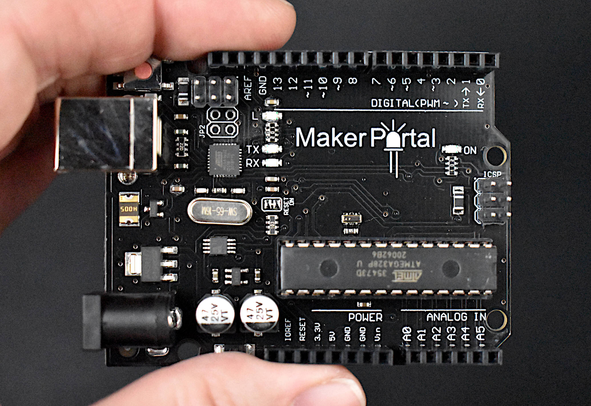
The Maker Portal Uno board is the centerpiece of many of the projects carried out in our maker spaces. The Uno board is capable of reading a wide range of sensors using analog-to-digital conversion, SPI, I2C, UART, and other common protocols. The Uno board can be used to control motors, OLED/LCD displays, and LEDs. The Arduino Uno board shown here is the official Maker Portal microcontroller, which we use in many of our projects!
Included in the Arduino Uno Package:
Maker Portal Arduino Uno Rev3 Board
Black USB Cable (1m in Length)
Specifications for Arduino Uno Rev3 Board:
ATmega328P chip with Arduino Bootloader
14 digital pins, 6 analog pins
10-bit analog-to-digital converter (ADC)
5V-12V Supply Tolerance
3.3V and 5.0V output pins
16 MHz clock
5 PWM pins, I2C support, SPI support , UART support
ATmega16U2 USB TTL, compatible with Linux, Windows, and Mac
Black Stylish Finish
Fully Integrated with Arduino IDE software

3.7V LiPo batteries are useful for low-power Arduino IoT applications. The 600mAh battery shown here can power a standard Arduino Uno board for a few days under moderate processing conditions, and up to several months with the right sleep routines and modifications (power down, no LED, etc.)!
Included in the LiPo Battery Kit for Arduino:
1x 600mAh LiPo Battery
1x USB Charger
1x JST to DuPont Connector (For Wiring to Arduino)
Features of the 3.7V LiPo Battery Kit for Arduino:
600mAh LiPo Battery with USB Charger
3.7V Battery Voltage
JST connector for direct wiring to Arduino

The INMP441 is a 3.3V MEMS microphone that uses Inter-IC Sound (I2S) to communicate with devices capable of audio recording via the I2S interface. The INMP441 is a great choice for voice inputs, sound localization, and other applications where an array of microphones can be used to identify and characterize acoustic systems. The INMP441 is compatible with Raspberry Pi stereo audio recording.
Tutorial with Raspberry Pi can be found here: Recording Stereo Audio on a Raspberry Pi
Included in the I2S MEMS Microphone Package:
1x INMP441 MEMS Microphone
1x 6-pin Solder Header
Features of the INMP441 MEMS I2S Microphone:
14mm Board Diameter, Low Profile
60Hz - 15kHz Frequency Response within -3dB Roll-Off
-26dBFS Sensitivity at 1kHz, 94dB Input
61dBA Signal-to-Noise Ratio (SNR)
-87dBFS Noise Floor
44.1kHz - 48kHz Sample Rates
Stereo Input Capabilities (L/R Channels)
Raspberry Pi Compatible

Radio Frequency Identification (RFID) is a common technology used for access control in schools and offices, animal identification, and product asset tracking. The MFRC522 module is a 13.56MHz RFID reader/writer that uses SPI to communicate with devices. The MFRC522 is compatible with both Arduino and Raspberry Pi, and a large range of RFID tags and cards. The kit we have assembled comes with an MFRC522 module, 6 RFID tags (3 fobs, 3 cards), and a 3D printed fixture for holding the MFRC522 - which makes getting started with RFID for Arduino very easy.
Included in the MFRC522 RFID Kit for Arduino:
1x MFRC522 RFID Module
6x RFID Tags (3x Cards, 3x Fobs)
1x 3D Printed Fixture
4x M3 Screws and Nuts for Affixing the MFRC522 Module to the Fixture
9x Female-to-Male Jumper Wires
Some Features of the MFRC522 RFID Module:
3.3V and 5.0V Supply Voltage
13.56MHz Operating Frequency
SPI Communication (Arduino, Raspberry Pi Compatible)
Capable of Communication with MIFARE Tags
10cm Read Range (between tag and reader)
Active Area: 30mm x 30mm
Module Dimensions: 36mm x 36mm x 7.5mm (accounting for pin headers)
MFRC522 Datasheet
See our tutorial on the MFRC522 with Arduino!
Some Features of the RFID Card:
Fully Read/Write Enabled
Can change their UID, and sectors
85.5mm x 54mm
13.56MHz Frequency Coils
MIFARE 1K Tags
Some Features of the RFID Fobs:
Read Enabled
Can write data, just not UID or manufacturer sectors
32mm x 40mm
13.56MHz Frequency Coils
MIFARE 1K Tags

The ATGM336H GPS module is a tiny (13mm x 16mm) constellation positioning and navigation device that is capable of connecting with up to six satellites to approximation its geolocation on earth. The ATGM336H is a great low-profile alternative to the similar NEO-6M GPS module that is commonly used in the Arduino/Raspberry Pi sphere. The ATGM336H has an accuracy of 2.5m and is capable of updating its coordinates 1-10 times per second. The GPS module uses a serial protocol to communicate with the Arduino platform (similar to the NEO-6M). Many of the libraries that work with other GPS modules also work with the ATGM336H, making it a great replacement for projects that require smaller geometries or weigh very little.
Included in the ATGM336H GPS Module Package:
1x ATGM336H GPS Module
1x 5-Pin Header
1x External GPS Antenna
Features of the ATGM336H GPS Module:
Dimensions: 13mm x 16mm
2.7V - 3.6V Supply Voltage
Average Power Consumption: <25mA (@3.3V)
Communicates with: BeiDou Navigation Satellite Systems (BDS) and Global Navigation Satellite Systems (GNSS)
32 Tracking Channels
Reads up to six satellite navigation systems and implement joint positioning, navigation,
and timing.
2.5m Positioning Precision
~32s to First Fix
1Hz-10Hz Update Rate
Serial Baudrate: 9600 (default)
Operational Temperature Range: -40℃ to +85℃
Read the Datasheet
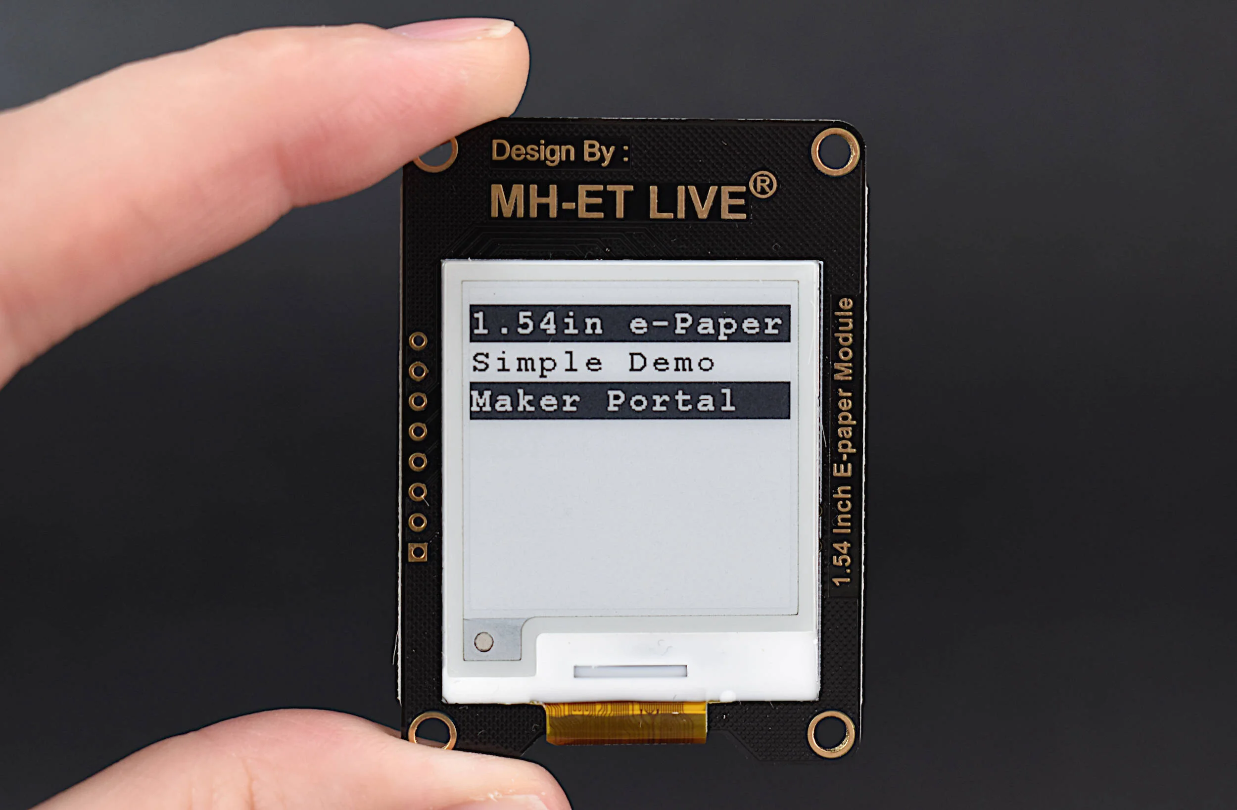
Electronic paper, known as e-Paper, is a common technology used in devices such as the Amazon Kindle and Nook eReaders and eBooks. The e-Paper module here uses SPI to communicate with Arduino boards and display text at very low power consumption. e-Paper is highly advantageous for displays that update very infrequently, as they can retain the last printed image on their screen even in the absence of power. The e-Paper module here can be powered via 3.3V or 5.0V, and is compatible with Arduino boards.
Included in the e-Paper Display for Arduino Package:
1x 1.54 inch e-Paper Display Module (200x200 Pixels)
1x JST XH 2.54mm to Dupont 8-Pin Connector
Features of the 1.54in e-Paper Display Module:
Module Dimensions: 40mm x 55mm
Active Area Dimensions: 1.09 in. x 1.09 in. [1.54 in. Diagonal]
1.8V-5.3V Supply Voltage
Power Consumption Profiles @ 3.3V:
3mA Idle Current
2mA - 7mA Update Current
Resolution: 200 x 200 Pixels (~185 dpi)
Full/Partial Refresh Capabilities
Max Refresh Rate ~2 seconds (Partial), ~5 seconds (Full)
SPI Interface (Compatible with Arduino and Raspberry Pi)
See our tutorial interfacing the e-Paper display and Arduino!

This kit is geared toward engineers and makers interested in learning about solar energy and how to characterize solar cells, understand nominal values in solar technology, and how to collect meaningful data. The kit comes with a solar panel, SD card and module for datalogging, a potentiometer, and LiPo battery for portability. The user just needs to add an Arduino board and breadboard and they can start logging solar data and make calculations in their local environment.
Included in the Solar Panel Datalogger Kit:
1x 2V, 120mA Solar Panel (54mm x 54mm) [Wire Colors May Vary]
1x INA226 Voltage/Current Measurement Module
1x 1kΩ Potentiometer (Rheostat in Experiments)
1x 3.7V, 600mAh LiPo Battery + USB Charger
1x SD Datalogger Module
1x 16GB SD Card
10pcs Female-to-Male + 10pcs Male-to-Male Jumper Wires
Features of the Solar Panel Datalogger Kit:
Characterize Solar Panel by Varying 1kΩ Potentiometer
600mAh Battery Allows for Roughly 1 Day+ of Datalogging (Depending on the Arduino Board and Sleep Routines)
16GB SD Card + Module Allow for Long-Term Datalogging
INA226 Reads 16-bit Voltage and Current
54mm x 54mm Solar Panel has 4 cells each 10mm x 38mm, for an Active Area of 15.2 cm-sq
See our tutorial on using the kit: Solar Panel Characterization and Experiments with Arduino

The SSD1306 display is an organic light emitting diode (OLED) device that is great for small-scale Arduino, Raspberry Pi, and Raspberry Pi Pico projects that involve real-time data acquisition, communication, and debugging. The display allows users to visualize and print out information related to sensors and modules — specifically when creating internet of things (IoT) nodes with microcontrollers and wireless/headless technologies. The OLED display is a versatile and has a low profile that requires just two wires for communication (I2C), which makes it easy to integrate and control.
Included in the SSD1306 OLED Display Kit:
1x SSD1306 OLED Display
1x 3D Printed Display Stand
4x M2.5 Screw for Attaching Display to Stand
4x Rubber Stoppers for Stability
4x Female-to-Male Jumper Wires
Features of the SSD1306 OLED Display:
3V-5V Supply Range
2mA - 24mA Consumption Range (Blank to All Pixels Bright)
128 x 64 Pixel HD Resolution
I2C 2-Wire Protocol (I2C address: 0x3C)
White Display Colors Against Dark Backdrop
Compatible with Arduino, Raspberry Pi, and Raspberry Pi Pico
Module Dimensions: 25mm x 27mm
Active Display Dimensions: ~ 21mm x 12.5mm (0.96” Diagonal)
Arduino Tutorial with SSD1306 here
Raspberry Pi Pico Tutorial with SSD1306 here
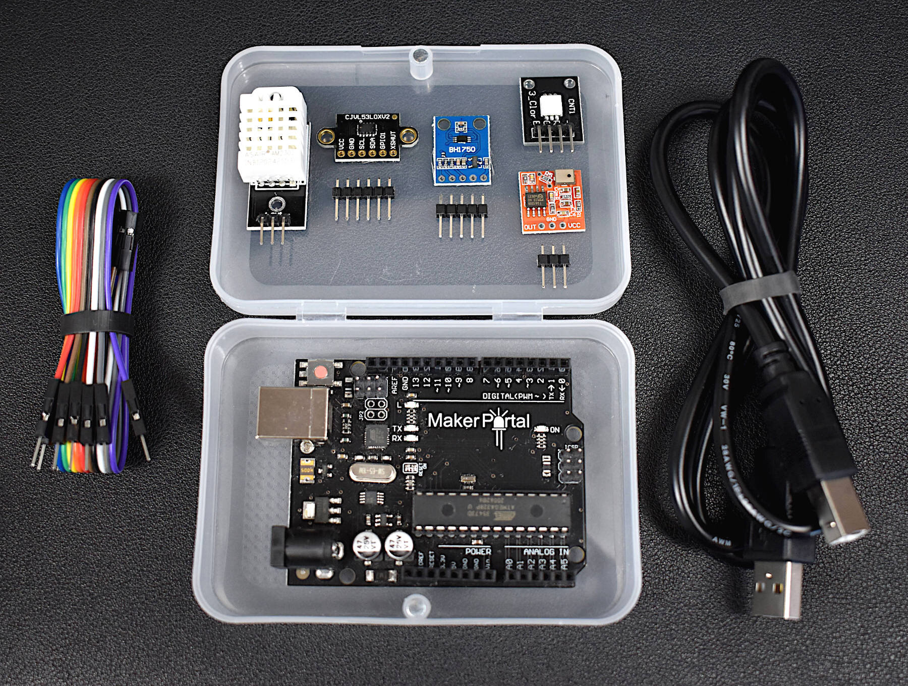
This Arduino starter kit has been tailored directly to engineers interested in real-world applications involving sensors. We avoided many of the out-of-date sensors that often accompany Arduino kits and targeted several relevant and interesting areas of engineering: temperature and humidity sensing, infrared time-of-flight distance sensing, and visible spectrum light intensity detection, and MEMS microphone audio sensing. In conjunction with these sensors, the kit also comes with an Arduino Uno microcontroller, jumper wires for connecting the sensors, an RGB LED indicator, and plastic component enclosure.
Included in the Arduino Starter Kit for Engineers (Sensor Suite):
1x Maker Portal Arduino Uno Board
1x BH1750 Light Sensor
1x DHT22 Temperature and Humidity Sensor
1x VL53L0X Time-of-Flight Distance Sensor
1x MEMS Microphone
1x RGB LED
10x Male-to-Female Jumper Wires
1x Plastic Component Box
1x USB 2.0 Cable for Arduino
Features of the Arduino Starter Kit for Engineers (Sensor Suite):
Detect light, temperature, humidity, distance, and sound
All sensors have easy-to-use Arduino-compatible libraries
The kit fits snugly into the component box, excluding the USB cable
Each sensor has a real-world application for prototyping in topics ranging from: environmental monitoring, industrial engineering, obstacle avoidance in robotics, home automation, and more!
Component Specifications:
-Specifications for the Arduino Uno Board:
ATmega328P chip with Arduino Bootloader
14 digital pins, 6 analog pins
10-bit analog-to-digital converter (ADC)
5V-12V Supply Tolerance
3.3V and 5.0V output pins
16 MHz clock
5 PWM pins, I2C support, SPI support , UART support
ATmega16U2 USB TTL, compatible with Linux, Windows, and Mac
Black Stylish Finish
Fully Integrated with Arduino IDE software
-Features of the BH1750 Light Sensor:
3.3V - 5.0V Input Voltage
16-bit ADC: 1 - 65535 lx Range
8-60Hz Sample Rate
I2C 2-Wire Communication Protocol
Supply Current - 120 µA, Power-down Current 0.01 µA
Peak Current - 7mA
400nm - 700nm Wavelength Response
-Features of the DHT22 Temperature Sensor:
3.3-6V Supply Voltage
Operating ranges:
Relative Humidity: 0-100 %
Temperature -40 °C to 80 °C
Sample Rate ~ 2 seconds
Sensitivity:
Relative Humidity: ± 0.1 %
Temperature: ± 0.1 °C
Accuracy (Drift and calibration errors):
Relative Humidity: ± 2-5 %
Temperature: ±0.5 °C
-Features of the VL53L0X ToF Sensor:
3.3V Supply Voltage
<20 mA consumption
50mm - 1.2m range (default mode), 50mm - 2.2m range (long range mode)
5 Hz - 33 Hz Sample Rate
I2C Compatible with Arduino, Raspberry Pi
Class I Infrared Laser (safe under all conditions)
-Features of the Analog MEMS Microphone:
3.0V-7.0V Supply Range
-42dBV/Pa Sensitivity
59dBA Signal-to-Noise Ratio (SNR) @ 1kHz
16mm x 15mm x 3.1mm Module Dimensions
4.72mm x 3.76mm MEMS Microphone Dimensions
100Hz - 10kHz Frequency Range (within 4dB)
3mA - 10mA Average Consumption
SPM0404HD5-PB MEMS Microphone Datasheet

The TinyBlueX is a combination module that contains an ATtiny85 microcontroller and CC254x Bluetooth Low Energy chip that is compatible with Arduino and the BLExAR iOS app. The TinyBlueX is very low power and low profile, which makes it great for simple internet of things (IoT) applications. The TinyBlueX can read sensors and transmit the data back to an iOS device. The TinyBlueX can also be controlled using the BLExAR app to turn LEDs, motors, and actuators on and off using the ATtiny’s GPIO pins. Pins 2,3,7 are available on the module, allowing the user to control/read up to three different devices or sensors.
Included with the TinyBlueX Module:
1x TinyBlueX Module
1x ATtiny85 Microcontroller
1x CC254x Bluetooth Low Energy Module
8x Female-to-Male Jumper Wires
Features of the TinyBlueX Module:
Dimensions: 56mm x 35mm x 18mm (Assembled)
Arduino IDE Compatible (Arduino as ISP Required)
Removable ATtiny85 Microcontroller and BLE Module
3.6V - 5.5V Supply Voltage Range
Bluetooth Low Energy Communication
Compatible with BLExAR iOS App
3x Analog Input Pins (10-bit) [Pins 2,3,7]
3x General Purpose Input/Output (GPIO) Pins [Pins 2,3,7]
1x External Interrupt Pin [Pin 7]
0MHz - 10MHz @ 3.6V-5.5V, 0MHz - 20MHz @ 4.5V - 5.5V
Low Power Modes with Watchdog Timer
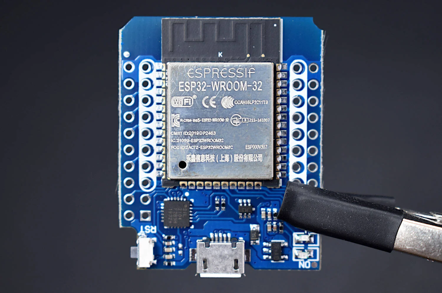
The ESP32 chip is a hybrid Bluetooth + WiFi-enabled microcontroller developed by Espressif Systems, the same developer as the widely popular ESP8266 WiFi-enabled microcontroller. The ESP32 board shown here is in a compact D1 Mini profile, which makes its geometry similar to their ESP8266 D1 Mini boards and other smaller Arduino boards. The ESP32 is fully compatible with the Arduino IDE and has a wide array of examples that allow users to get started with Bluetooth Classic, Bluetooth Low Energy (BLE), and WiFi servers and clients. The microcontroller has a fast CPU (240MHz), 12-bit ADC, peripheral communication (UART, SPI, I2C), and a wide array of GPIO pins. The ESP32 D1 Mini is a great choice for IoT applications.
Included in the ESP32 D1 Mini Package:
1x ESP32 D1 Mini Board
4x Female Dupont Pins (short), 2x Female Dupont Pins (long)
1x Micro USB Cable
Features of the ESP32 D1 Mini Bluetooth+WiFi Board:
Supply Voltage: 3.0 V ~ 3.6 V (VCC), 3.0V - 5.0V (USB and 5V)
Operating Voltage: 3.3V (GPIO pins)
Power Consumption:
30mA - 80mA (idle)
100mA - 240mA (WiFi/Bluetooth RX/TX)
10µA - 150µA (Deep Sleep)
5µA (RTC Timer Only)
Peripheral Interfaces: UART, SPI, I2C, LED PWM, Motor PWM, I2S, IR, pulse counter, GPIO, capacitive touch sensor, ADC, DAC
WiFi - 802.11 b/g/n (802.11n up to 150 Mbps) @2.4 GHz ~ 2.5 GHz
Bluetooth - Bluetooth v4.2 BR/EDR and BLE specification
Operating Temperature: –40 °C ~ +85 °C
40 Available GPIO Pins

The AMG8833 is a 64-pixel temperature sensor developed by Panasonic under the Grid-EYE® product line. The sensor contains an 8x8 array of infrared thermopiles, which approximate the temperature by measuring the infrared radiation being emitted from emissive bodies. The Grid-EYE communicates via the I2C bus, which also makes it compatible with Raspberry Pi and Arduino right out of the box. The AMG8833 contains an onboard lens that limits the viewing angle of the sensor to 60-degrees, which results in a sensing region useful for objects in the mid-field (as opposed to far-field or near-field). It also operates at 3.3V and 5V, at a sample rate of 1Hz-10Hz, with an approximate temperature resolution of 0.25°C over a range of 0°C to 80°C. The AMG8833 is useful for applications in thermal imaging, heat transfer analyses, human temperature monitoring, heating and air condition management, industrial control, and other applications in non-contact temperature measurement.
Included in the AMG8833 Thermal Camera Package:
1x AMG8833 Grid-EYE® 64-Pixel Infrared Array Module
1x 6-Pin Solder Header
Features of the AMG8833 Thermal Camera:
MEMS 64-Pixel Infrared Thermopile Array (8x8 Grid)
3.3V - 5.0V Supply Voltage
0℃ to 80℃ Measurement Range (at 0.25℃ Resolution)
± 2.5℃ Temperature Accuracy (Typical)
0.2mA to 4.5mA Current Consumption
1Hz - 10Hz Sample Rate Options
Operating Modes: Normal, Sleep, Interrupts (1s. 60s)
I²C Communication (SDA/SCL) [0x68 and 0x69 Selectable Address]
Onboard Thermistor (Ambient Temperature Sensing)
−20 ℃ to 80 ℃ Range
0.0625 ℃ Resolution
Compatible with Raspberry Pi and Arduino

Named after its french creator, Henri Pitot, a pitot tube is a device used to approximate the speed of vehicles traveling through air and other fluids. Pitot tubes, also called pitot-static tubes and Prandtl tubes, are primarily used as airspeed indicators on drones, airplanes, and other rotorcraft. Pitot tubes use basic fluid dynamics and the Bernoulli equation to approximate airspeed, or relative velocity, of a moving vehicle/flying object. The pitot tube here can be combined with our XGMP3v3 Differential Pressure Sensor to measure pressure, which is then converted to a digital signal using an Arduino board or other analog-to-digital converter (ADC). This final differential pressure can be used to derive airspeed or velocity of a moving object.
Included in the Pitot Tube Airspeed Sensor Package:
1x Metal Pitot Tube
2x Acrylic 2.5mm ID Tubing (75cm in Length)
1x XGMP3v3 Differential Pressure Sensor
1x JST-XH 3-Wire Connector (Colors May Vary)
Features of the Pitot Tube Airspeed Sensor:
3.3V Supply Voltage
0.2V - 2.7V Analog Output
Dimensions (Pitot Tube): 100mm x 16mm x 6mm
Flexible 2.5mm Tubing (75cm Length)
Aluminum Machined Metal
Selectable Pressure (Velocity) Range:
-0.5kPa to +0.5kPa -> -28m/s to +28m/s
-1.0kPa to +1.0kPa -> —41m/s to +41m/s
-2.5kPa to +2.5kPa -> -64m/s to +64m/s
Features of the XGMP3v3 Differential Pressure Sensor:
3.3V Operating Voltage
24mA Max Power Consumption (10mW)
Analog Output Range: 0.2V - 2.7V
Measurement Accuracy: ±2.5% Full-Scale [kPa]
Temperature Compensated from 0°C - 60°C
Selectable Pressure Span:
-0.5kPa to +0.5kPa (Most Sensitive)
-1.0kPa to +1.0kPa
-2.5kPa to +2.5kPa (Similar to MPXV7002DP)
Absolute Maximums: ±2x Pressure Max, -10°C to 85°C Operating Temperature
For Use with Non-Corrosive Gas (Air, Inert [Helium, Neon, Argon, etc.])
JST-XH Connector Makes Connection to Raspberry Pi or Arduino Simple
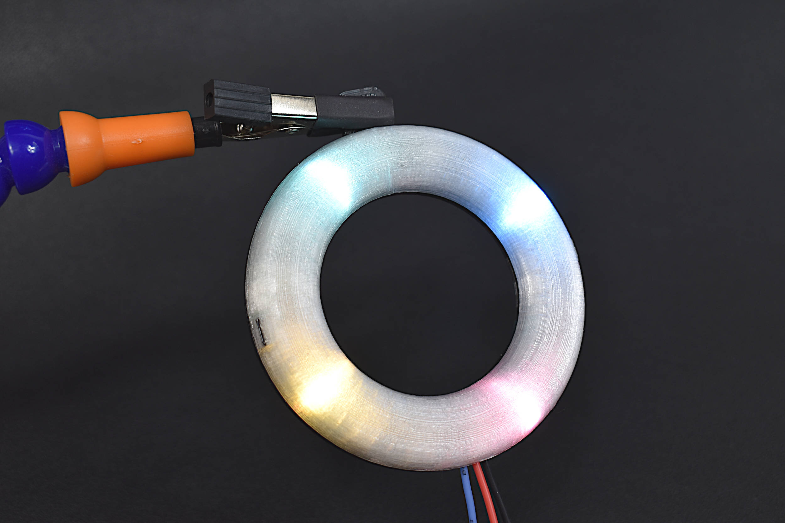
The RGB LED ring light uses an array of 16 surface mounted light-emitting diodes that are programmable by Raspberry Pi computers, Arduino boards, and Raspberry Pi Pico microcontrollers. The RGB LEDs used in the 16-pixel ring light are similar to the common WS2812B LEDs. Each LED is individually addressable, which allows users to control all 16 LEDs. Each RGB LED can be altered using 24-bit configuration commands, which results in 16,777,216 possible colors for each LED.
Included in the 16-Pixel RGB LED Ring Light:
1x 16-Pixel RGB LED Ring
1x 3D-Printed Enclosure (Translucent Dome, Black Backing Plate)
Features of the 16-Pixel RGB LED Ring Light:
16 RGB LEDs Soldered to PCB Ring
5V Supply Voltage
0.55A Max Current Consumption (35mA per LED)
Dimensions:
PCB: 72mm Radius, 3mm Thickness
Enclosure: 78mm x 88mm x 10mm
All 16 LEDs are Individually Addressable
16,777,216 Possible Colors Per LED
Only 3-Wires Required for Control and Power
3D-Printed Enclosure Allows for Holding and Attaching (M3 Screw)
Compatible with Arduino, Raspberry Pi, Raspberry Pi Pico

The QuadMic Array is a 4-microphone array based around the AC108 quad-channel analog-to-digital converter (ADC) with Inter-IC Sound (I2S) audio output capable of interfacing with the Raspberry Pi. The QuadMic can be used for applications in voice detection and recognition, acoustic localization, noise control, and other applications in audio and acoustic analysis. The QuadMic can be connected to the header of a Raspberry Pi computer and used to record simultaneous audio data from all four of its microphones. Some applications of the QuadMic are: characterizing noise sources, room and spatial geometries, and other aspects of acoustic systems.
Included in the QuadMic 4-Microphone Array Package:
1x QuadMic 4-Microphone Array
Features of the QuadMic 4-Microphone Array:
Four SPU0414HR5H MEMS Microphones
100Hz - 10kHZ Flat (4dB) Frequency Response
16kHz Sample Rate for Each Microphone
I2S Audio Protocol
I2C Output Connector
GPIO 12/13 Available via Output Connector
12 Addressable RGB LEDs via SPI
Compatible with Raspberry Pi
Electronic Wiring Diagram can be found here
Read about the AC108 Analog-to-Digital Converter here
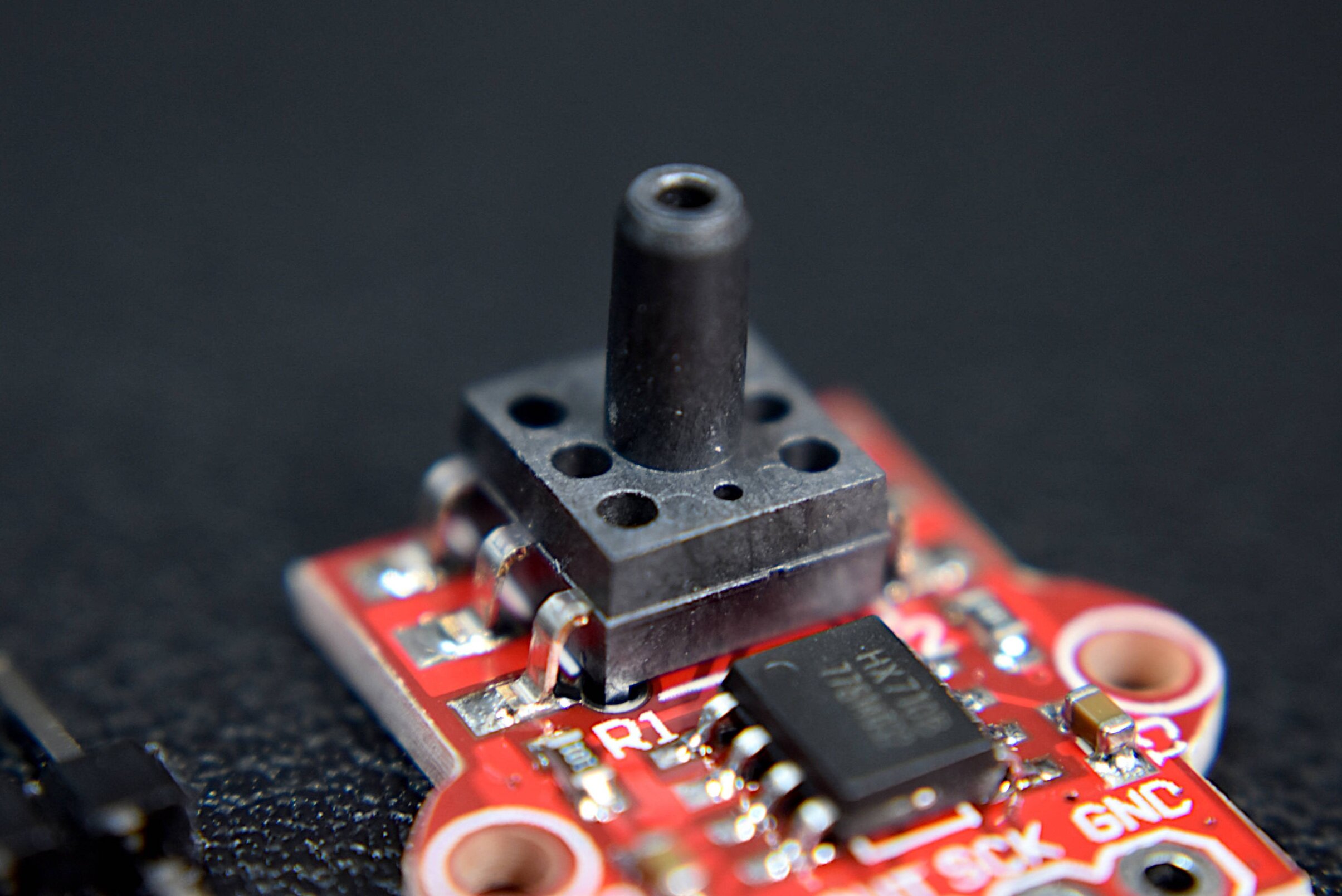
The MPS20N0040D is a gauge pressure transducer that approximates pressures from roughly -10kPa to +10kPa. The sensor uses an Hx710B 24-bit analog-to-digital converter (ADC) and signal amplifier to amplify the output from the MPS20N0040D to 0V - 5V. The response of the MPS20N0040D can be approximated using an Arduino board via 2-wire serial protocol.
Included in the MPS20N0040D Sensor Package:
1x MPS20N0040D Ported Pressure Sensor
2x Solder Pin Sets
Some Features of the MPS20N0040D Pressure Sensor:
5V Operating Voltage
-10kPa - 10kPa Measurable Pressure Range
+25mV DC Offset, 50mV Full Scale Output
Linear Response Between Voltage and Pressure
Compatible with 2.5mm Tubing
Arduino and Raspberry Pi Compatible

The USB microphone is perfect for audio projects that involve Raspberry Pi due to its slim profile, long attached USB cable, and its frequency response. This USB microphone can be used for acoustic signal processing, voice recognition, musical instrument recording, or engineering applications in machine noise monitoring.
Included in package:
USB Condenser Microphone
USB Microphone Specs:
1.5 m long cable
Omnidirectional response pattern
USB 2.0 (works with Raspberry Pi)
50 Hz - 16 kHz frequency response
Microphone Size (without windscreen): 6.5 cm x 0.7 cm
44.1 kHz/48kHz USB Sample Rate Selection
-38 dB ± 3 dB Sensitivity

The XGMP3v3 differential pressure sensor is particularly useful for lower pressure scenarios involving small DC fan analyses, respirators, and low velocity flow tests through pipes and channels. The XGMP3v3 can also be used to approximate airspeed of drones using a pitot tube. Additionally, if one port of the XGMP3v3 is kept open to the atmosphere, the pressure sensor can be calibrated with a U-tube manometer.
Included in the XGMP3v3 Differential Pressure Sensor Package:
1x XGMP3v3 Differential Pressure Sensor
1x 3-Wire JST-XH to Dupont Connector (Colors May Vary)
Features of the XGMP3v3 Differential Pressure Sensor:
3.3V Operating Voltage
24mA Max Power Consumption (10mW)
Analog Output Range: 0.2V - 2.7V
Measurement Accuracy: ±2.5% Full-Scale [kPa]
Temperature Compensated from 0°C - 60°C
Selectable Pressure Span:
-0.5kPa to +0.5kPa (Most Sensitive)
-1.0kPa to +1.0kPa
-2.5kPa to +2.5kPa (Similar to MPXV7002DP)
Absolute Maximums: ±2x Pressure Max, -10°C to 85°C Operating Temperature
For Use with Non-Corrosive Gas (Air, Inert [Helium, Neon, Argon, etc.])
JST-XH Connector Makes Connection to Raspberry Pi or Arduino Simple
Radio Frequency Identification (RFID) is a common technology used for access control in schools and offices, animal identification, and product asset tracking. The MFRC522 module is a 13.56MHz RFID reader/writer that uses SPI to communicate with devices. The MFRC522 is compatible with both Arduino and Raspberry Pi, and a large range of RFID tags and cards. The kit we have assembled comes with an MFRC522 module, 6 RFID tags (3 fobs, 3 cards), and a 3D printed fixture for holding the MFRC522 - which makes getting started with RFID for Arduino very easy.
Included in the MFRC522 RFID Kit for Arduino:
1x MFRC522 RFID Module
6x RFID Tags (3x Cards, 3x Fobs)
1x 3D Printed Fixture
4x M3 Screws and Nuts for Affixing the MFRC522 Module to the Fixture
9x Female-to-Male Jumper Wires
Some Features of the MFRC522 RFID Module:
3.3V and 5.0V Supply Voltage
13.56MHz Operating Frequency
SPI Communication (Arduino, Raspberry Pi Compatible)
Capable of Communication with MIFARE Tags
10cm Read Range (between tag and reader)
Active Area: 30mm x 30mm
Module Dimensions: 36mm x 36mm x 7.5mm (accounting for pin headers)
MFRC522 Datasheet
See our tutorial on the MFRC522 with Arduino!
Some Features of the RFID Card:
Fully Read/Write Enabled
Can change their UID, and sectors
85.5mm x 54mm
13.56MHz Frequency Coils
MIFARE 1K Tags
Some Features of the RFID Fobs:
Read Enabled
Can write data, just not UID or manufacturer sectors
32mm x 40mm
13.56MHz Frequency Coils
MIFARE 1K Tags
This kit is geared toward engineers and makers interested in learning about solar energy and how to characterize solar cells, understand nominal values in solar technology, and how to collect meaningful data. The kit comes with a solar panel, SD card and module for datalogging, a potentiometer, and LiPo battery for portability. The user just needs to add an Arduino board and breadboard and they can start logging solar data and make calculations in their local environment.
Included in the Solar Panel Datalogger Kit:
1x 2V, 120mA Solar Panel (54mm x 54mm) [Wire Colors May Vary]
1x INA226 Voltage/Current Measurement Module
1x 1kΩ Potentiometer (Rheostat in Experiments)
1x 3.7V, 600mAh LiPo Battery + USB Charger
1x SD Datalogger Module
1x 16GB SD Card
10pcs Female-to-Male + 10pcs Male-to-Male Jumper Wires
Features of the Solar Panel Datalogger Kit:
Characterize Solar Panel by Varying 1kΩ Potentiometer
600mAh Battery Allows for Roughly 1 Day+ of Datalogging (Depending on the Arduino Board and Sleep Routines)
16GB SD Card + Module Allow for Long-Term Datalogging
INA226 Reads 16-bit Voltage and Current
54mm x 54mm Solar Panel has 4 cells each 10mm x 38mm, for an Active Area of 15.2 cm-sq
See our tutorial on using the kit: Solar Panel Characterization and Experiments with Arduino

A venturi tube is a measurement device that uses the pressure differential between two sections that differ in diameter. Using Bernoulli’s principle, the velocity and flow rate can be approximated from the pressure differential measured across the two areas within the venturi tube. The venturi tube is a popular method of calculated volumetric flow rates for gases, water and oils, and other internally flowing fluids. The venturi tube given here is designed specifically for use with 80mm DC fans. The venturi tube has been used to verify fluid dynamics theory while also characterizing the relationship between duty cycle and flow rate of the fan. The fan included in this kit has been characterized to output approximately 75 cubic feet per minute (CFM). The kit also includes the XGMP3v3 differential pressure sensor (similar to the MPXV7002DP), which makes the kit a complete bundle for measuring real-world flows through a venturi tube.
See the Venturi Tube in action on Youtube.
Included in the Venturi Tube Flow Meter Kit:
1x 3D Printed Venturi Tube (236mm x 85mm x 85mm)
1x XGMP3v3 Differential Pressure Sensor (with JST-XH Connector)
1x 80mm x 38mm 12V DC Fan (+4x Screw Set)
2x Silicone Tubing (OD: 5mm, ID: 2.5mm, Length: 35cm Each)
20pcs Jumper Wires
Features of the Venturi Tube Flow Meter:
Dimensions: 236mm x 85mm x 85mm
Inlet Diameter: 76mm, Throat Diameter: 57mm
Roughness ~ 32μm
Most 80mm DC Fans Can be Affixed to Tube
Two Pressure Taps for 5mm Tubing (Inlet, Throat)
Features of the XGMP3v3 Differential Pressure Sensor:
-2.5 kPa to +2.5 kPa Measurement Range
3.3V Supply Voltage
24mA Max Power Consumption (10mW)
Analog Output Range: 0.2V - 2.7V
Measurement Accuracy: ±2.5% Full-Scale [kPa]
Temperature Compensated from 0°C - 60°C
Absolute Maximums: ±2x Pressure Max, -10°C to 85°C Operating Temperature
For Use with Non-Corrosive Gas (Air, Inert [Helium, Neon, Argon, etc.])
JST-XH Connector Makes Connection to Raspberry Pi or Arduino Simple
Features of the 12V 80mm x 38mm DC Fan:
Dimensions: 80mm x 38mm (Diameter x Thickness)
Input Voltage: 12V
Power Consumption: ~ 8.4W (12V, 0.7A)
Duty Cycle 25% - 100%
Volumetric Flow Rates: ~30CFM - 75CFM
Fairly noisy at high RPM (duty cycle 100%, 5500RPM, roughly 50dBA)

The NEMA 17 stepper motor (Model: 17HS4023) is a powerful motor capable of microstepping, high-speed rotation, and high-torque holding. The stepper motor kit also includes a DRV8825 stepper driver and motor bridge, which makes getting started with motor driving easy. With the stepper bridge, only a Raspberry Pi or Arduino, 12V supply, and five jumper wires are needed to control the NEMA 17 stepper motor. This stepper kit can be used in applications involving 3D printers, DIY CNC machines, precise camera movement, LiDAR rotation, among others!
Included in the NEMA 17 Stepper Motor Kit:
1x NEMA-17HS4023 Stepper Motor
1x DRV8825 Stepper Driver with Heat Sink
1x DRV8825 Driver Bridge
5x Female-to-Female Jumper Wires
1x Stepper-to-Bridge Connector Wire
Features of the NEMA-17HS4023 Motor:
42mm x 42mm x 23mm (LxWxH - Approximate Dimensions)
Micro-stepping down from 1.8° down to 0.05625°
Wide Voltage Supply Range: 5V - 24V
0.7A - 1.0A per phase (2-phases total)
130g Weight
13 N·cm Holding Torque
Clockwise and Counterclockwise Rotation
Rotation speeds at 1.8° Increments up to ~500RPM (12V, no load), ~1800RPM (24V, no load)
Controllable via Arduino or Raspberry Pi
Tutorial on the NEMA 17 Kit here

This kit uses known masses to calibrate a load cell using the linear response between strain gauges and weight under gravity. The HX711 is easily integrated with Arduino. Using this calibration kit, makers and engineers can build a low-weight measurement scale, a real-time measurement system for aerodynamic loads, a density measurement system using water, and so much more!
The Load Cell Calibration Kit includes:
1x 1 kg Load Cell
1x HX711 Strain Gauge 24-bit Amplifier
2x 3D Printed supports (one bottom, one top)
1x M5 Hex Screw, 1x M4 Hex Screw (for affixing the supports to the load cell)
3x rubber stoppers to prevent slipping
5x calibrated masses (20g, 10g, 5g, 2g, 1g)
An example video demonstration of the load cell can be found at:
NOTE: Because the supports are 3D printed, they may be slightly different from the ones photographed. They will function and appear exactly the same, with slight variations in minor striations or patterning.
The SSD1306 display is an organic light emitting diode (OLED) device that is great for small-scale Arduino, Raspberry Pi, and Raspberry Pi Pico projects that involve real-time data acquisition, communication, and debugging. The display allows users to visualize and print out information related to sensors and modules — specifically when creating internet of things (IoT) nodes with microcontrollers and wireless/headless technologies. The OLED display is a versatile and has a low profile that requires just two wires for communication (I2C), which makes it easy to integrate and control.
Included in the SSD1306 OLED Display Kit:
1x SSD1306 OLED Display
1x 3D Printed Display Stand
4x M2.5 Screw for Attaching Display to Stand
4x Rubber Stoppers for Stability
4x Female-to-Male Jumper Wires
Features of the SSD1306 OLED Display:
3V-5V Supply Range
2mA - 24mA Consumption Range (Blank to All Pixels Bright)
128 x 64 Pixel HD Resolution
I2C 2-Wire Protocol (I2C address: 0x3C)
White Display Colors Against Dark Backdrop
Compatible with Arduino, Raspberry Pi, and Raspberry Pi Pico
Module Dimensions: 25mm x 27mm
Active Display Dimensions: ~ 21mm x 12.5mm (0.96” Diagonal)
Arduino Tutorial with SSD1306 here
Raspberry Pi Pico Tutorial with SSD1306 here
This Arduino starter kit has been tailored directly to engineers interested in real-world applications involving sensors. We avoided many of the out-of-date sensors that often accompany Arduino kits and targeted several relevant and interesting areas of engineering: temperature and humidity sensing, infrared time-of-flight distance sensing, and visible spectrum light intensity detection, and MEMS microphone audio sensing. In conjunction with these sensors, the kit also comes with an Arduino Uno microcontroller, jumper wires for connecting the sensors, an RGB LED indicator, and plastic component enclosure.
Included in the Arduino Starter Kit for Engineers (Sensor Suite):
1x Maker Portal Arduino Uno Board
1x BH1750 Light Sensor
1x DHT22 Temperature and Humidity Sensor
1x VL53L0X Time-of-Flight Distance Sensor
1x MEMS Microphone
1x RGB LED
10x Male-to-Female Jumper Wires
1x Plastic Component Box
1x USB 2.0 Cable for Arduino
Features of the Arduino Starter Kit for Engineers (Sensor Suite):
Detect light, temperature, humidity, distance, and sound
All sensors have easy-to-use Arduino-compatible libraries
The kit fits snugly into the component box, excluding the USB cable
Each sensor has a real-world application for prototyping in topics ranging from: environmental monitoring, industrial engineering, obstacle avoidance in robotics, home automation, and more!
Component Specifications:
-Specifications for the Arduino Uno Board:
ATmega328P chip with Arduino Bootloader
14 digital pins, 6 analog pins
10-bit analog-to-digital converter (ADC)
5V-12V Supply Tolerance
3.3V and 5.0V output pins
16 MHz clock
5 PWM pins, I2C support, SPI support , UART support
ATmega16U2 USB TTL, compatible with Linux, Windows, and Mac
Black Stylish Finish
Fully Integrated with Arduino IDE software
-Features of the BH1750 Light Sensor:
3.3V - 5.0V Input Voltage
16-bit ADC: 1 - 65535 lx Range
8-60Hz Sample Rate
I2C 2-Wire Communication Protocol
Supply Current - 120 µA, Power-down Current 0.01 µA
Peak Current - 7mA
400nm - 700nm Wavelength Response
-Features of the DHT22 Temperature Sensor:
3.3-6V Supply Voltage
Operating ranges:
Relative Humidity: 0-100 %
Temperature -40 °C to 80 °C
Sample Rate ~ 2 seconds
Sensitivity:
Relative Humidity: ± 0.1 %
Temperature: ± 0.1 °C
Accuracy (Drift and calibration errors):
Relative Humidity: ± 2-5 %
Temperature: ±0.5 °C
-Features of the VL53L0X ToF Sensor:
3.3V Supply Voltage
<20 mA consumption
50mm - 1.2m range (default mode), 50mm - 2.2m range (long range mode)
5 Hz - 33 Hz Sample Rate
I2C Compatible with Arduino, Raspberry Pi
Class I Infrared Laser (safe under all conditions)
-Features of the Analog MEMS Microphone:
3.0V-7.0V Supply Range
-42dBV/Pa Sensitivity
59dBA Signal-to-Noise Ratio (SNR) @ 1kHz
16mm x 15mm x 3.1mm Module Dimensions
4.72mm x 3.76mm MEMS Microphone Dimensions
100Hz - 10kHz Frequency Range (within 4dB)
3mA - 10mA Average Consumption
SPM0404HD5-PB MEMS Microphone Datasheet
Named after its french creator, Henri Pitot, a pitot tube is a device used to approximate the speed of vehicles traveling through air and other fluids. Pitot tubes, also called pitot-static tubes and Prandtl tubes, are primarily used as airspeed indicators on drones, airplanes, and other rotorcraft. Pitot tubes use basic fluid dynamics and the Bernoulli equation to approximate airspeed, or relative velocity, of a moving vehicle/flying object. The pitot tube here can be combined with our XGMP3v3 Differential Pressure Sensor to measure pressure, which is then converted to a digital signal using an Arduino board or other analog-to-digital converter (ADC). This final differential pressure can be used to derive airspeed or velocity of a moving object.
Included in the Pitot Tube Airspeed Sensor Package:
1x Metal Pitot Tube
2x Acrylic 2.5mm ID Tubing (75cm in Length)
1x XGMP3v3 Differential Pressure Sensor
1x JST-XH 3-Wire Connector (Colors May Vary)
Features of the Pitot Tube Airspeed Sensor:
3.3V Supply Voltage
0.2V - 2.7V Analog Output
Dimensions (Pitot Tube): 100mm x 16mm x 6mm
Flexible 2.5mm Tubing (75cm Length)
Aluminum Machined Metal
Selectable Pressure (Velocity) Range:
-0.5kPa to +0.5kPa -> -28m/s to +28m/s
-1.0kPa to +1.0kPa -> —41m/s to +41m/s
-2.5kPa to +2.5kPa -> -64m/s to +64m/s
Features of the XGMP3v3 Differential Pressure Sensor:
3.3V Operating Voltage
24mA Max Power Consumption (10mW)
Analog Output Range: 0.2V - 2.7V
Measurement Accuracy: ±2.5% Full-Scale [kPa]
Temperature Compensated from 0°C - 60°C
Selectable Pressure Span:
-0.5kPa to +0.5kPa (Most Sensitive)
-1.0kPa to +1.0kPa
-2.5kPa to +2.5kPa (Similar to MPXV7002DP)
Absolute Maximums: ±2x Pressure Max, -10°C to 85°C Operating Temperature
For Use with Non-Corrosive Gas (Air, Inert [Helium, Neon, Argon, etc.])
JST-XH Connector Makes Connection to Raspberry Pi or Arduino Simple
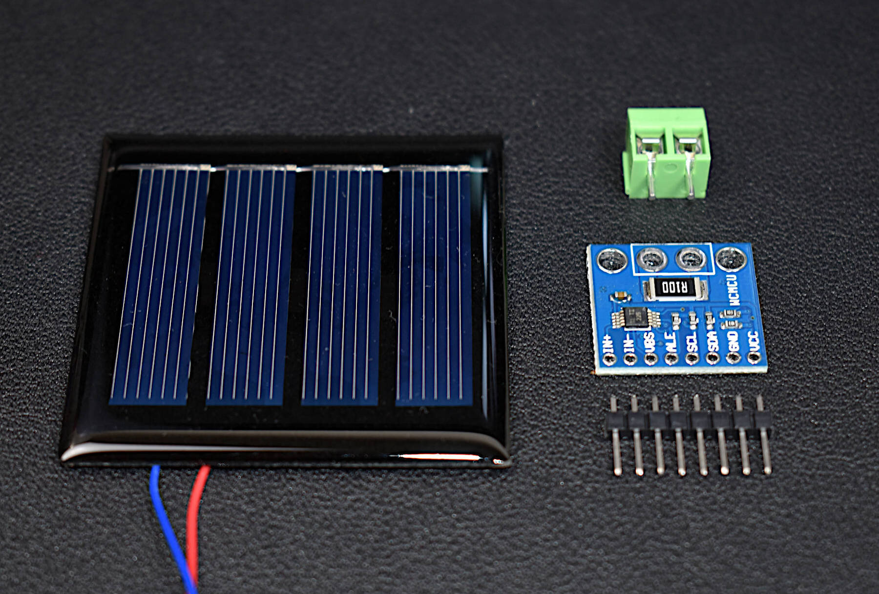
Solar panels are an essential component of the renewable energy field. The solar panels here are 2V 120mA cells that are paired with an INA226 current sensor. The goal of this kit is to allow users to test the power output from the solar panel using the current sensor and a microcontroller. Any microcontroller can be used to interface with the INA226, which gives panel voltage, current, and output power. This combination can help engineers identify the approximate predicted output from their solar panel or solar panel array to approximate efficiency of their energy harvesting, irradiance in a specific geographic region, or characterize internet of things setup requirements.
Included in the Solar Panel Power Metering Kit:
1x 200mW Solar Panel (@ 1.6V) [Wire Colors May Vary]
1x INA226 Current Sensor
1x Terminal Block
1x 8-Pin Solder Header
Features of the Solar Panel:
54mm x 54mm Dimensions
200mW Peak Power Output
2.1V Open-Circuit Voltage
123mA Short Circuit Current
1.6V Max Power Voltage
120mA Max Power Current
Epoxy Finish (Waterproof Cells, not Electronics)
Soldered Breakout Wires
Features of the INA226 Current Sensor:
Senses Bus Voltages From 0V to 36V
2.7-V to 5.5-V Input Power Supply Range
I2C Communication (Raspberry Pi, Arduino, Pico-Compatible)
High-Side or Low-Side Sensing
16-bit Analog-to-Digital Converter
Current, Voltage, and Power Outputs
Low-Power Operation (330μA Quiescent Current)
NOTE: The terminal block overlaps slightly with the shunt resistor on the INA226, however, it does not affect the functionality of the sensor.
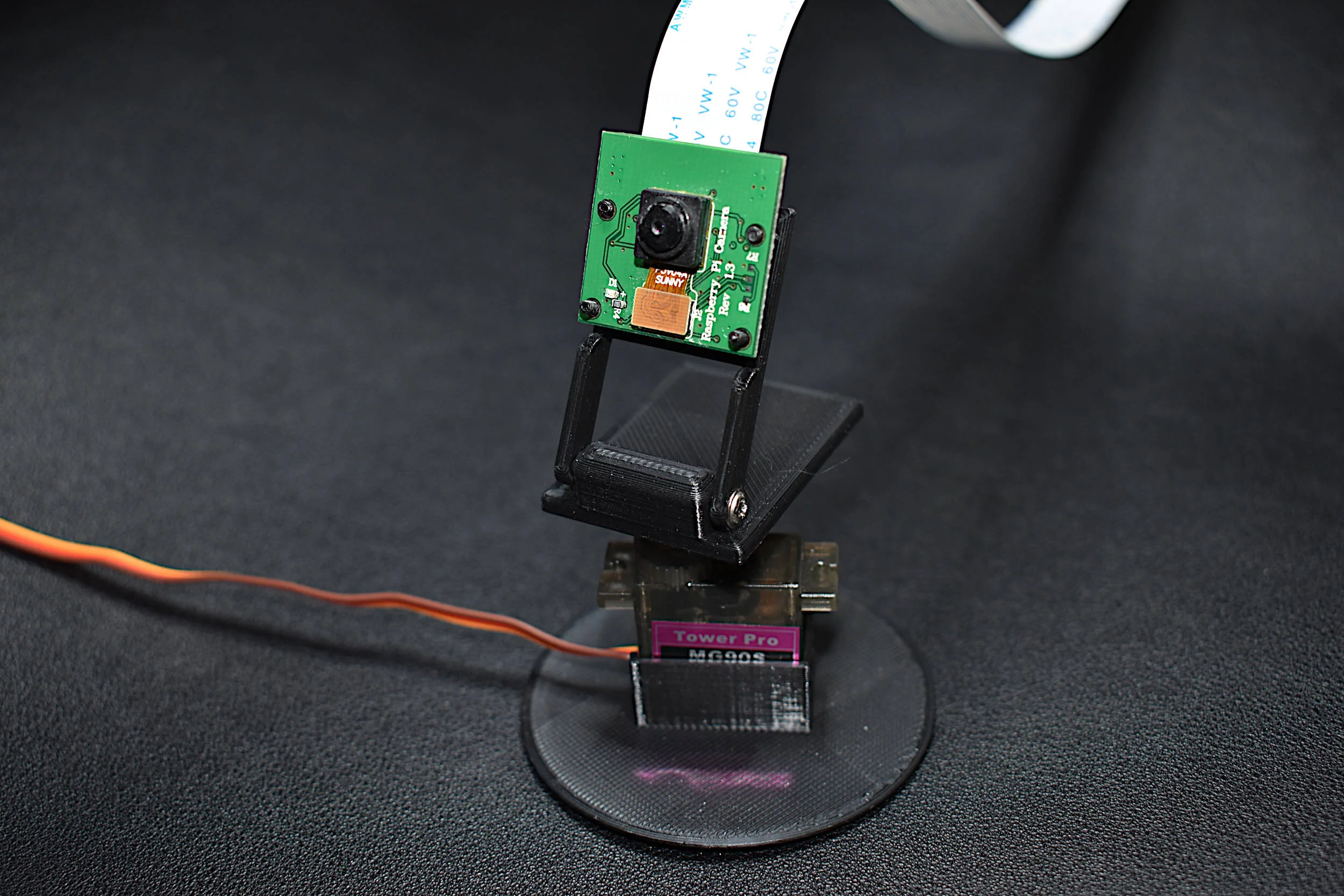
Control your PiCamera from a Raspberry Pi using a servo motor and 3D printed parts. This bundle uses an MG90S micro servo to pan the PiCamera over a 180° plane. Using Python, the user can record video captured by the Raspberry Pi and control the movement of the panning camera (we even wrote a tutorial on this: here).
Included in the PiCamera + Servo Camera Pan Bundle:
1x PiCamera V1.3
1x 50cm PiCamera Cable
1x MG90S Micro Servo
6x Pieces Servo Horns and Screws
3x Pieces 3D-Printed Servo Stand, Horn Part, and PiCamera Holder
3x Rubber Pads for Stabilization
Some Features of the PiCamera:
5MP Max photograph resolution (2592 x 1944 = 5,038,848 pixels)
Ribbon Cable that attaches directly to the Raspberry Pi
Pixel Size: 1.4 x 1.4 μm
Lens: f=3.6 mm, f/2.9
Viewing Angle: 54° x 41°
Max video resolution: 1080p @ 30fps
Max frame rate: 480p @ 90fps
Selectable video resolutions: 1080p @ 30fps, 720p @ 60fps, 480p @ 90fps
Sensor size: 3.67mm x 2.74mm (1/4" format)
Camera Module PCB dimensions: 25mm x 24mm (9mm thickness)
Some Features of the MG90S:
Input Voltage: 4.8V - 6.0V
Operating Current (5.0V): ~2.7mA (idle), ~70mA (no load), ~400mA (Stall)
Rotation Angle: 0° - 180° (Resolution: 1°)
Max Speed (5.0V): 0.6 deg/ms (full 180 degrees in 300 ms)
Largest Dimensions: 12mm x 32.5mm x 32.5mm
MG90S Datasheet

The combination of an HC-SR04 Ultrasonic distance sensor and an MG90S micro servo creates an Arduino-compatible radar kit, where users can control the servo with an Arduino board while reading the HC-SR04 ultrasonic distance output. The resulting output can be combined with a serial reader program in Python on virtually any computer (including a Raspberry Pi!) to create a DIY radar sensor.
Included in the Radar Kit:
1x HC-SR04 Ultrasonic Distance Sensor
1x MG90S Micro Servo Motor
3x 3D-Printed Bracket for Mounting
6x Servo Hardware (3 screws for mounting, and 3 horns)
9x Jumper Wires for Connecting to an Arduino Board
3x Rubber Stoppers for stability
Features of the Radar Kit:
~20 Hz Update Rate
Distance Measurements up to 4m
Rotation Arc: 0° - 180°
Arduino and Raspberry Pi Compatible
Arduino Tutorial here
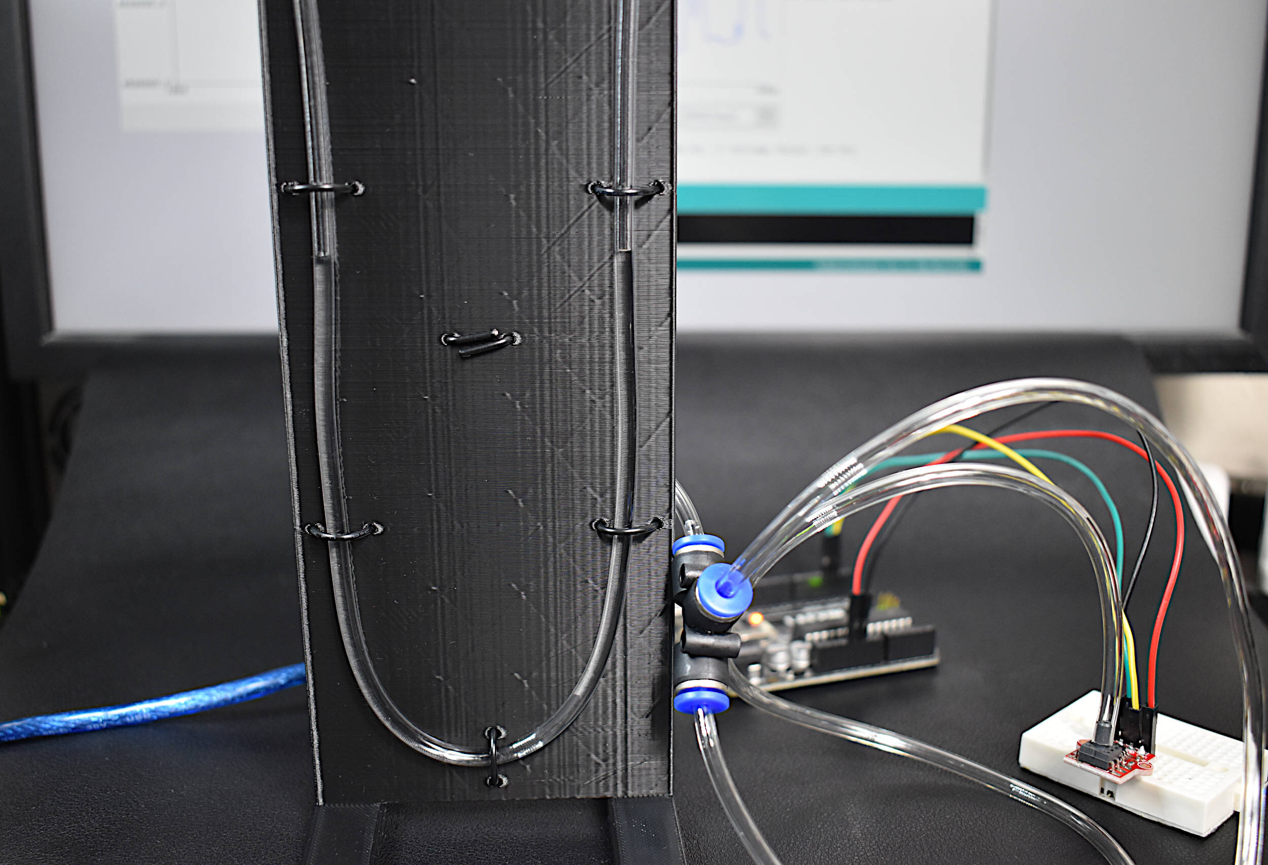
The pressure transducer calibration kit uses an analog manometer to calibrate an MPS20N0040D pressure transducer using 2.5mm tubing and a tee junction. When the tee junction is put under a given pressure, the manometer water level changes accordingly, as does the signal produced by the pressure transducer. The water level can be measured and approximated as a pressure (-2kPa - +2kPa measurement range).
Included in the Pressure Transducer Calibration Kit:
1x 3D Printed Manometer
2.5mm x 4mm Tubing (3m in length)
1x MPS20N0040D Pressure Transducer
4mm Tee Junction
4x Jumper Wires
1x Mini Breadboard
Some Features of the Pressure Transducer Kit:
-2kPa to 2kPa Calibration Range from Manometer
0kPa - 30kPa (approximate) Operating Range for MPS20N0040D
4mm Tee Junction Connects MPS20N0040D and Manometer
MPS20N0040D compatible with Arduino + Raspberry Pi
MPS20N0040D Operates at 5V

The ID809 fingerprint reader has been integrated with a SAMD21 microcontroller to create the all-in-one fingerprint reader shown here. The advantage of this reader is that no external controller are needed. Simply plug the USB cable into your computer, and enjoy registering new fingerprints onto the database, accepting stored fingerprints, and rejecting invalid fingerprints! The sensor shown here is fully compatible with the Arduino IDE, and allows users to use fingerprint recognition over a wide range of applications.
Included in the Capacitive Fingerprint Reader Kit:
1x ID809 Fingerprint Reader
1x SAMD21G18 Microcontroller
1x Mini Breadboard
1x USB Cable
1x 3D Printed Enclosure
Some Features of the Capacitive Fingerprint Reader:
360° fingerprint readability and matching
Stores up to 80 fingerprints
Verification time: ~300-400 ms
Capacitive image resolution: 508 dpi
32bit 48MHz microcontroller (SAMD21G18)
USB-C to Micro USB -> USB 2.0 Cable
Arduino compatible
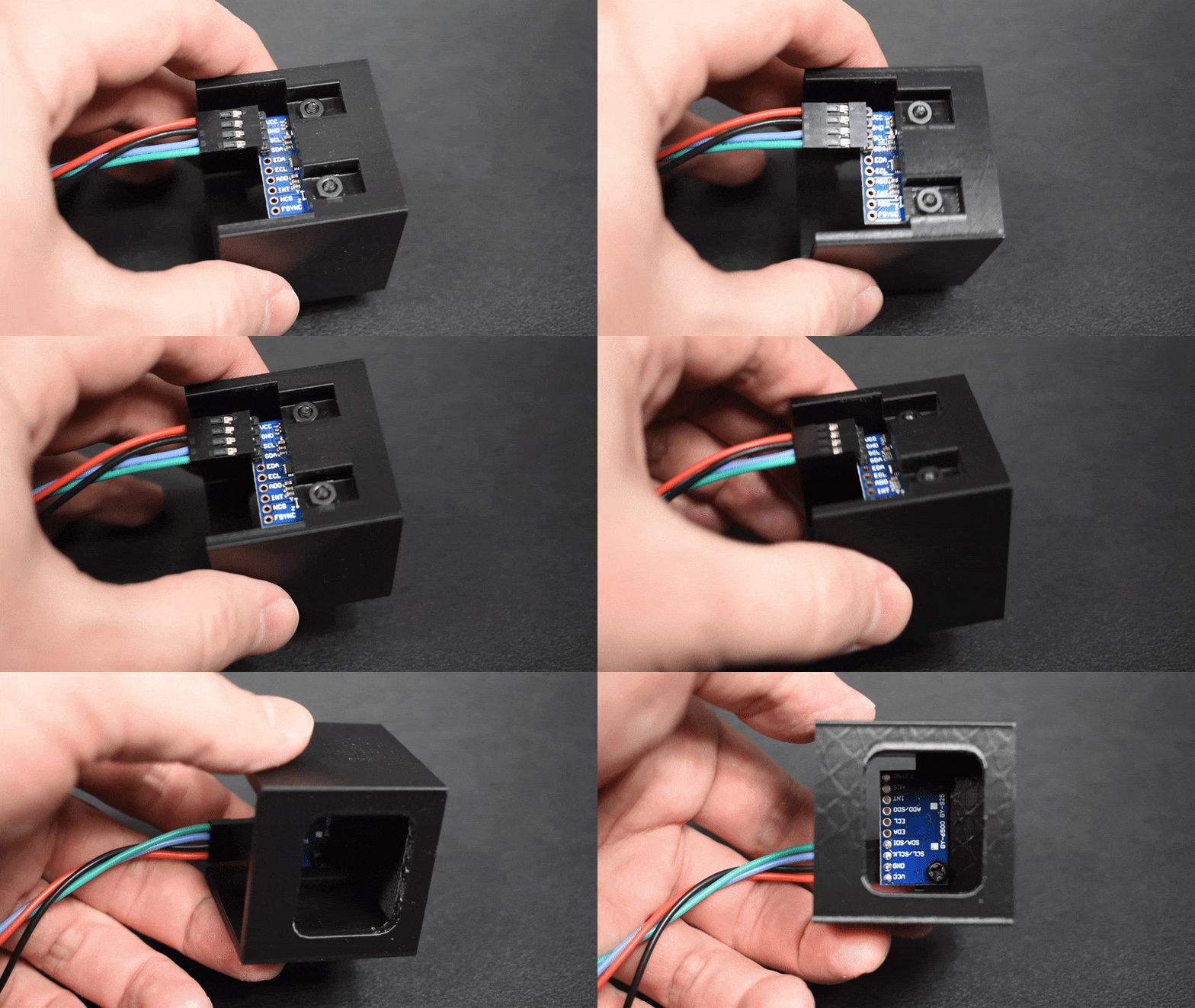
The calibration of an inertial measurement unit (IMU) is made simple in this kit by combining an MPU9250 sensor with a 3D-printed cube. The gyroscope contained within the MPU9250 can be calibrated under steady conditions. Similarly, the accelerometer can be calibrated by rotating each axis in the direction of gravity. Lastly, the magnetometer can be calibrated by rotating the block 360 degrees around each axis. The calibration block is specially designed for rotation and calibration of all nine degrees-of-freedom (9-DoF) available to the MPU9250.
See the IMU Calibration Series Tutorials: Part I, Part II, Part III
Included in the IMU Calibration Block Kit:
1x Calibration Block (40mm Cube)
1x MPU9250 Inertial Measurement Unit
2x Nylon Screws, 2x Nylon Nut
1x 4-Pin Dupont Connection Wire (24-AWG, 1 meter)
2x 10-Pin Header
PLA Material and Nylon Screws are used to Prevent Ferritic Interference with Magnetometer
Features of the IMU Calibration Block:
Designed for Calibration of all 9-DoF of the IMU
Holes for attaching MPU9250
Smooth to allow for rotation
90-degree edges for proper calibration in each direction
Sleek black design
Features of the MPU9250 IMU:
Easily attachable to the calibration block
Accelerometer/Gyroscope (MPU6050)
Magnetometer (AK8963)
Fast sample rates ~100Hz (Magnetometer), 1-8kHz (Accel/Gyro)
16-bit Analog-to-Digital Conversion for each of the 9-DoF
I2C Communication Protocol
Low Power Consumption
Compatible with Arduino and Raspberry Pi
MPU9250 Datasheet
3-Axis Accelerometer (MPU6050)
±2g, ±4g, ±8g and ±16g with 16-bit ADC
~4000Hz Data Sample Rate
3-Axis Gyroscope (MPU6050)
±250, ±500, ±1000, and ±2000°/sec with 16-bit ADC
~8000Hz Max Data Sample Rate
3-Axis Magnetometer (AK8963)
±4800µT with 14-bit ADC
~ 8-100Hz Data Sample Rate
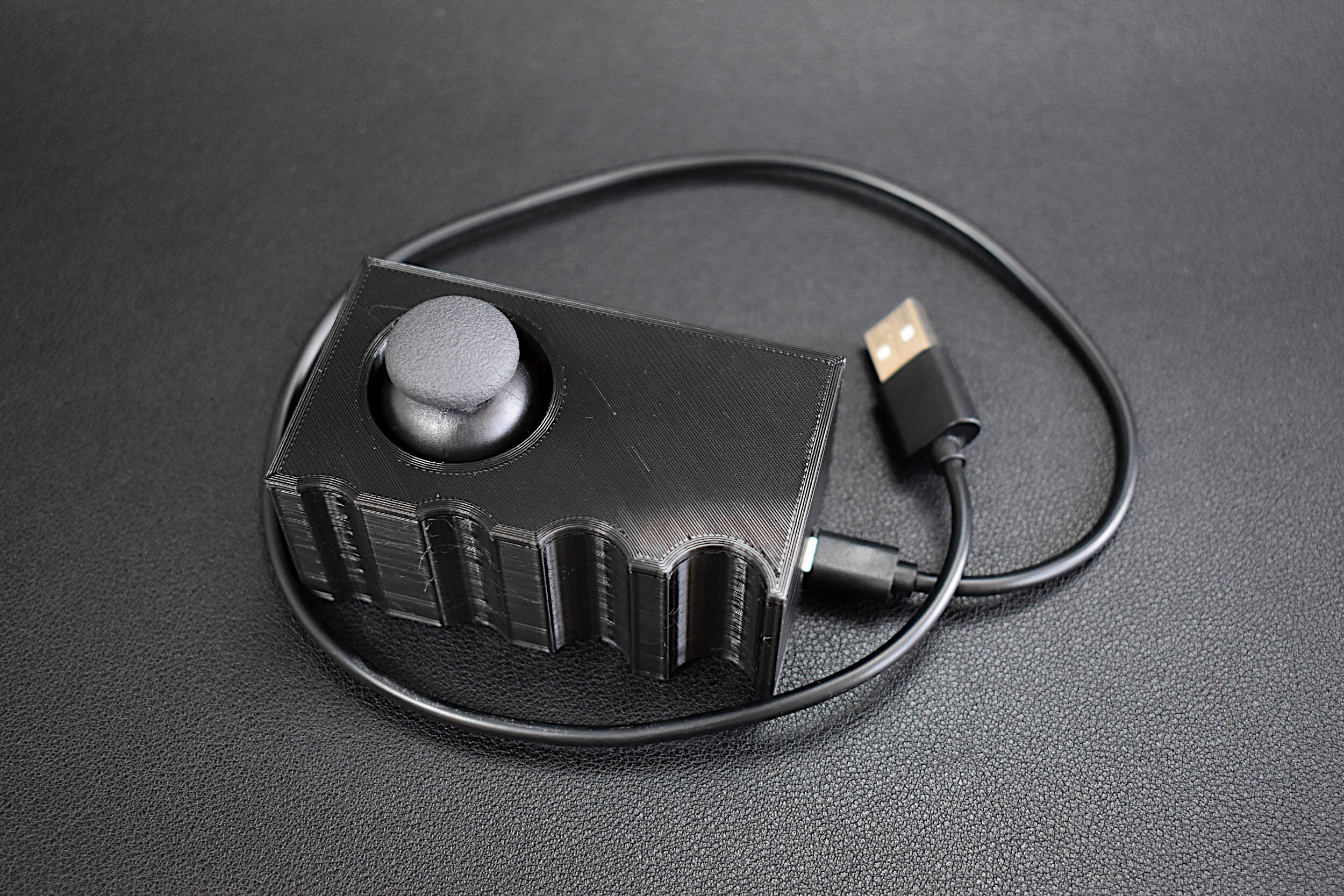
Haptics in the context of modern technology refers to the interaction between human touch and responses provided by computer interfaces in an attempt to emulate real-world stimuli. We designed a haptic vibrational feedback kit using the movements of an analog joystick. The Arduino platform can be used to read the analog joystick and control the response of a vibration motor shaking in the user's hand. An ESP32 D1 Mini microcontroller is selected as the microcontroller that is included in the kit. The ESP32 is chosen due to its fast processor, which will decrease the time delay between joystick reading and the haptic vibrational feedback response. This kit is meant to introduce users to haptic feedback by integrating simple components into a handheld device compatible with Arduino. The resulting handheld device delivers vibrational responses based on changes in joystick position. The full tutorial that deploys this kit is given here.
Included in the Haptic Vibration Joystick Kit:
1x Haptic Vibration Motor/Buzzer
1x Analog Joystick
1x ESP32 D1 Mini Microcontroller (w/ Micro USB Cable)
1x 3D Printed Joystick Enclosure
5x M3 Screws for Affixing Motor and Joystick to Enclosure
8x Male-to-Female Jumper Wires
Features of the Haptic Vibration Joystick Kit:
3-Degree-of-Freedom Joystick (x, y, button)
3.7V Vibration Motor
3D Printed Enclosure for Real-Time Haptic Feedback Response
ESP32 D1 Mini Microcontroller (BLE/WiFi Compatible)
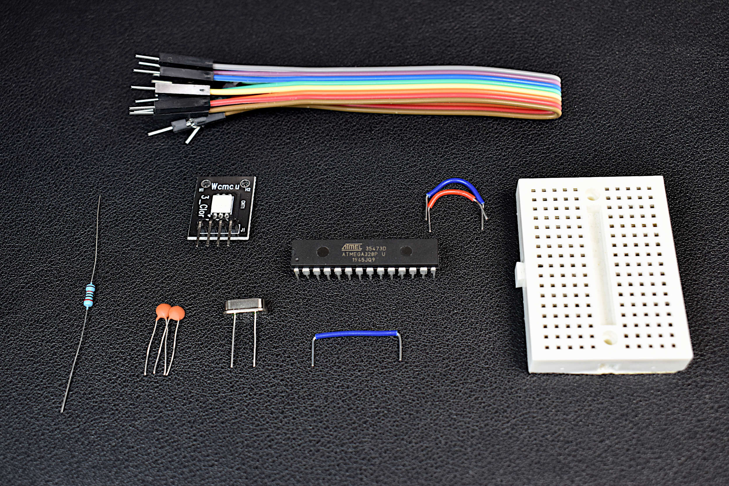
An Arduino board is a collection of electronic components that enable users to rapidly prototype with a central microcontroller. LEDs, regulators, and fixtures make getting started with the Arduino platform simple. This DIY Arduino kit aims to demystify the Arduino board by taking the essential components of an Arduino board and putting them into one kit. The DIY Arduino kit uses an ATmega328P-U as the central microcontroller, and some essential electronic components necessary to function as an Arduino board.
Included in the DIY Arduino Kit:
1x ATmega328P-U Microcontroller
1x 16MHz Quartz Crystal Oscillator
2x 22pf Capacitors
1x 20kOhm Resistor
1x RGB LED
1x Mini Breadboard
10x Jumper Wires
Included in the DIY Arduino Kit + Uno Board:
Everything Above + Arduino Uno Rev3 Board for Programming the DIY Board
Some Features of the DIY Arduino Kit:
Fully-Functional Arduino Board
Low Power Consumption due to lack of LEDs or Regulators
Arduino Already Bootloaded onto the ATmega328P
Low Profile Breadboard, smaller than an Arduino Uno board
RGB LED for testing code
2.7V - 5.5V Operating Range
5µA Low Current when Powered Down (3.3V, 16MHz)
8mA Working Current (3.3V, 16MHz)
Jumper Wires for Uploading Code, and Interacting with Sensors and Motors
Some Features of the ATmega328P-U Chip:
28-Pins in a Dual In-Line Packaging (2x14 pins)
Capabilities: SPI, I2C, USART, PWM
2.7V - 5.5V Input Voltage Range
1µA - 1.5mA Power Consumption (3V, 4MHz)
10-bit Analog-to-Digital Converter (8-channels)
Interrupt Capabilities (2-channel)
32KB of Flash Memory for Programming
0MHz-16MHz Frequency Capabilities (External Crystals)
8-bit/16-bit Timers
Compatible with Arduino IDE

The Raspberry Pi Pico is a microcontroller designed by the Raspberry Pi foundation. The Pico is a groundbreaking board that is meant to use MicroPython in its native micro USB port. The RP2040 is the microcontroller chip at the center of the Pico, which has a dual-core Arm Cortex M0+ processor, capable of clocking at 133 MHz, which is much faster than many of the Arduino boards currently on the market. The Pico has GPIO pins and interfaces such as: SPI, UART, I2C, PWM, and a 12-bit analog-to-digital converter (ADC). This Raspberry Pi Pico comes with the Pico microcontroller, 2x 20-pin solder header, and a micro-USB cable.
Included with the Raspberry Pi Pico Microcontroller:
1x Raspberry Pi Pico Board
2x 20-pin Headers
1x Black 0.5m Micro USB Cable
Features of the Raspberry Pi Pico:
1.8V - 5.5V Input Voltage
21 mm × 51 mm Board Geometry
RP2040 microcontroller
Dual-core Arm Cortex-M0+ processor (Clock Speed up to 133 MHz)
264KB on-chip SRAM, 2MB on-board QSPI Flash
26x GPIO pins (3x 12-bit Analog Inputs)
2x UART, 2x SPI, 2x I2C, 16x PWM
1x USB 1.1 controller and PHY, with host and device support
8x Programmable I/O (PIO) state machines for custom peripheral support
Operating temperature -20°C to +85°C
Low-power sleep and dormant modes
Onboard Temperature sensor
Accelerated integer and floating-point libraries on-chip
The MLX90640 is a 768-pixel (32 x 24), low-cost thermal camera. It uses an array of infrared detectors (and filters) to detect the radiation given off by nearby objects by taking advantage of Planck’s radiation law. The MLX90640 is most notable because of its easy-to-use Python libraries that allow it to be read by Raspberry Pi computers. The MLX90640 can be used to map and record high-resolution temperature maps at refresh rates of up to 64 times per second (64Hz).
NOTE: There are two versions here, 1. an unsoldered board that needs to be soldered to be wired properly; and 2. a version that has a breakout connector that can be connected directly to a Raspberry Pi via the JST Dupont connector.
Included in the MLX90640 Thermal Camera Sensor Package:
1x MLX90640 Thermal Camera (32 x 24 Pixels, 55° x 35°)
Pin Header
5x Male-to-Female Jumper Wires (or JST Dupont connector for breakout version)
Features of the MLX90640 Thermal Camera:
Object Detection Temperatures: -40°C to +300°C
3V-6V Supply Voltage
20mA Average Current Consumption
32 x 24 Resolution, 768 Pixels in Total
55° x 35° Field of View
I²C Communication (Address: 0x33)
Ambient Temperature Operating Range: -40°C to +85°C
Raspberry Pi and Arduino Compatible
JST Dupont Breakout Pinouts:
Black for GND
Red for V+
Blue for SDA
Yellow for SCL
MLX90640 Datasheet
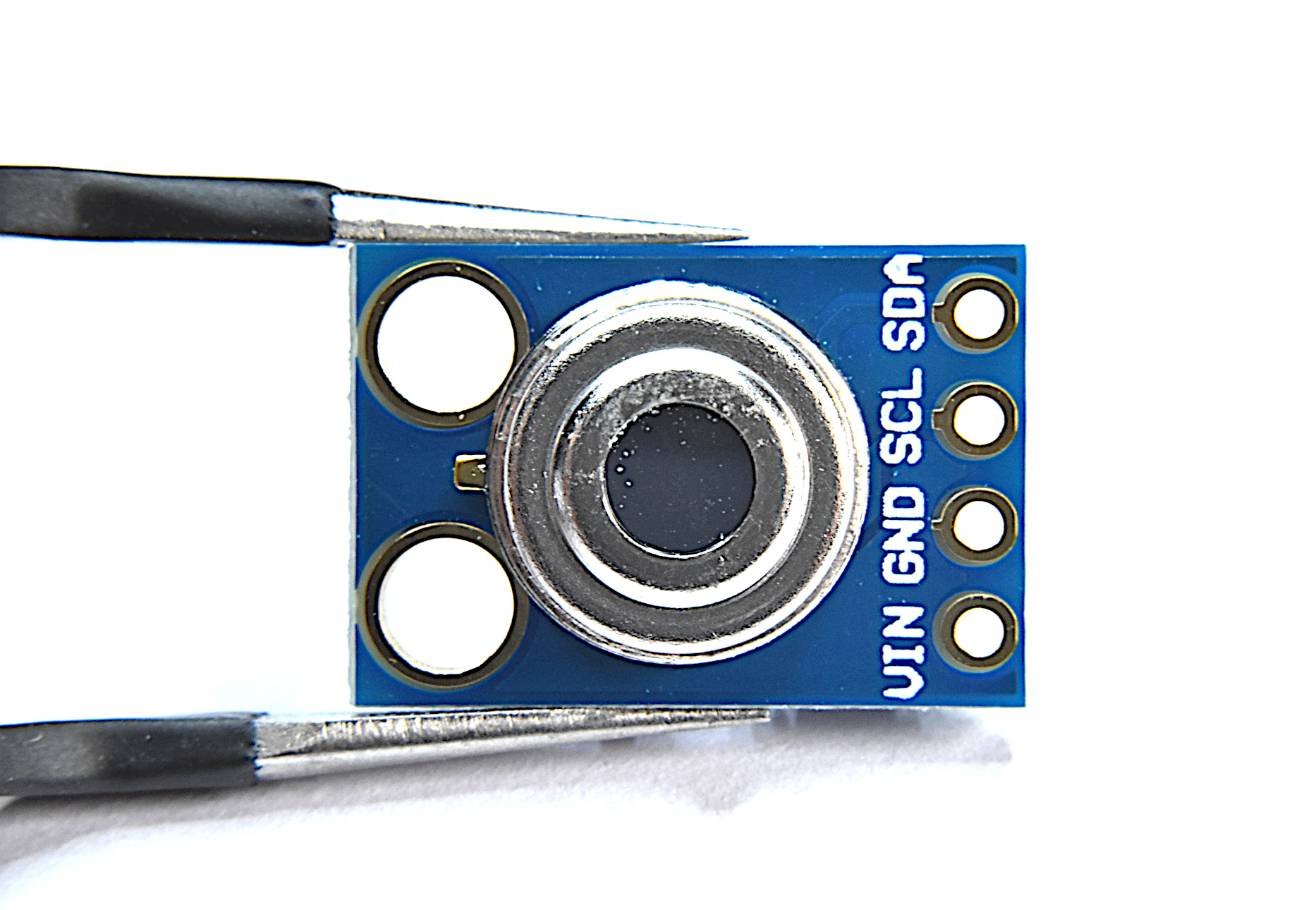
What comes in this package:
MLX90614 IR sensor
MLX90614 Specs:
3-5V Operating Voltage
-70 °C to 380 °C Object Temperature Measurement Range
0.5 °C Accuracy (0-50 °C)
0.02 °C Measurement Resolution’
At 35° Viewing Angle, Temperature is half the 0° Angle Value
I2C Wiring works with Arduino and Raspberry Pi
Full Datasheet download here

Analog joysticks can be found in video game controllers, drone and remote-controlled vehicle controllers, and heavy machinery controllers. They’re great for just about any precision control project where human interfacing is desired. The analog joystick here is one that is compatible with both Arduino and Raspberry Pi - and is a great tool for learning coding, robotic control, and functional interaction between humans and computers.
Included in the Analog Joystick Package:
1x Analog Joystick Controller
5x Female-to-Male Jumper Wires
Some Features of the Analog Joystick:
5V Input Supply
2-D Rotational + 1-D Push Analog Responses
360° Rotation in 2-D Plane
Rubber Joystick Finish for Gripping
Smooth Rotation
Clicking sound for Push Notification
Compatible with Raspberry Pi + Arduino
Code for measuring joystick rotations can be found at this tutorial:

Soil moisture can be measured using a variety of different techniques: gravimetric, nuclear, electromagnetic, tensiometric, hygrometric, among others. This sensor uses a capacitive method that exploits the dielectric properties of water in soil. Accurate measurement of soil water content is essential for applications in agronomy and botany - where the under- and over-watering of soil can result in ineffective or wasted resources.
Included in the Capacitive Soil Moisture Sensor Package:
1x Capacitive Soil Moisture Sensor
1x 3-Wire Connector
Features of the Capacitive Soil Moisture Sensor:
3.3V - 5.0V Supply Range
3.3V Operating Range
Analog Output 1.5 - 3.3V
Correlated with Volumetric Water Content 0 % - 100%
Compatible with Arduino and Raspberry Pi
Full tutorial can be found on blog here.
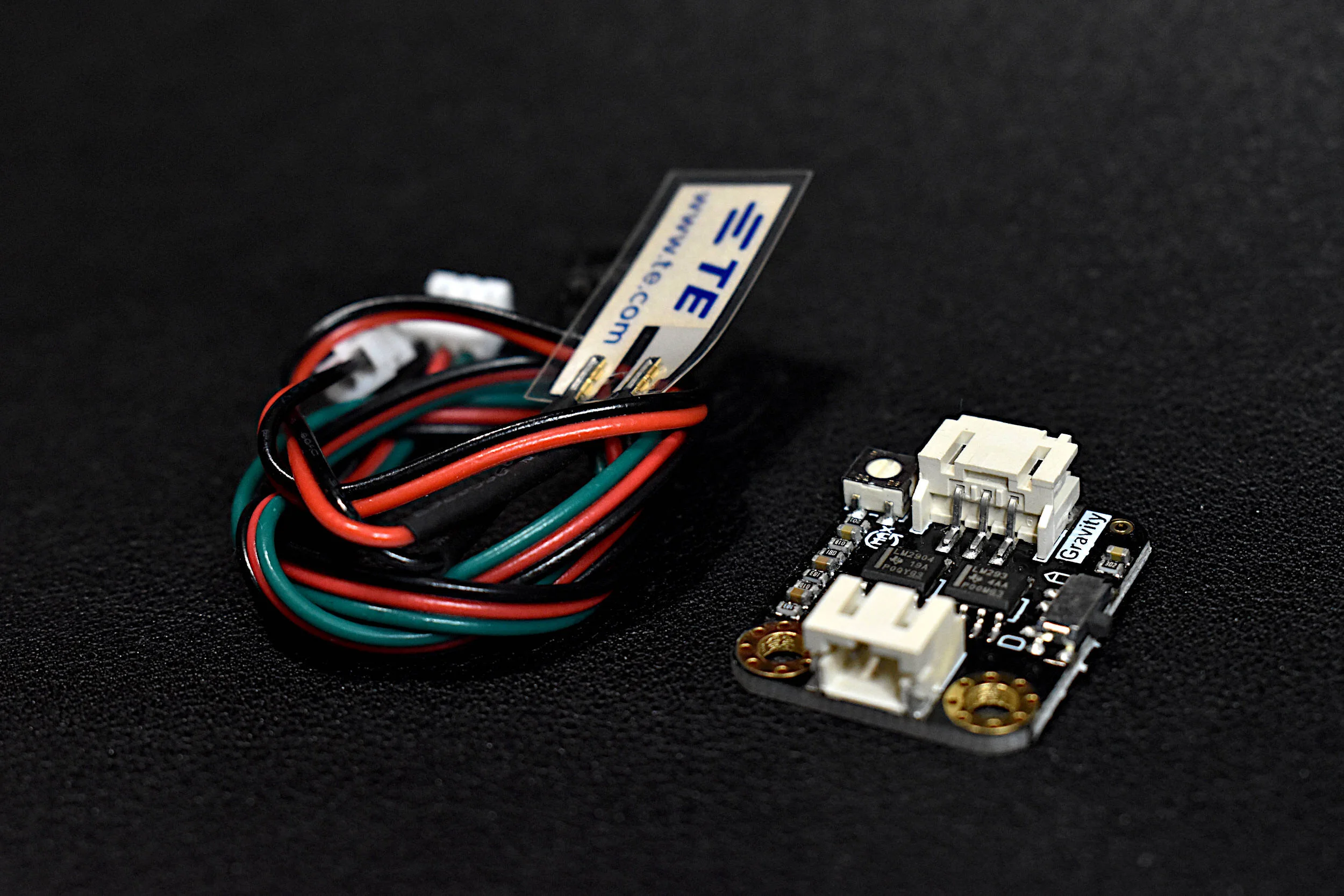
The piezo film sensor includes a tiny film that is capable of measuring minute vibrations and deflections from materials. The film sensor kit also comes with an amplifier that allows the user to determine the direction of the deflection as well as the approximate amplitude that is meaningful for either frequency or amplitude analyses in vibration.
Included in the Piezoelectric Vibration Sensor Kit:
1x piezo film
1x piezo amplification system
2x connecting wires
A vibration tutorial using the piezo film can be found on our site here.

The VL53L0X (sometimes GY-VL53L0XV2, CJVL53L0XV2, or VL53L0XV2) laser rangefinder uses a 940nm laser and the time-of-flight principle to approximate the distance between the sensor and a target object.
Included in the VL53L0X Package:
1x VL53L0X Sensor
Solder Pins
VL53L0X Specifications:
3.3V Supply Voltage
<20 mA consumption
50mm - 1.2m range (default mode), 50mm - 2.2m range (long range mode)
5 Hz - 33 Hz Sample Rate
I2C Compatible with Arduino, Raspberry Pi
Class I Infrared Laser (safe under all conditions)
The VL53L0X Sensor Datasheet can be found here.
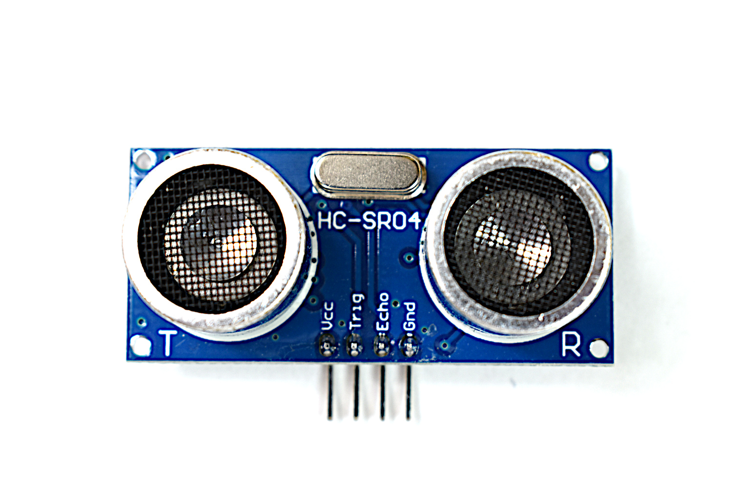
Ultrasonic distance sensor that is capable of measuring distances from 2cm - 4m. The HC-SR04 can be used in obstacle detection, radar emulators, and projects involving mapping of areas.
Included in the HC-SR04 Package:
1x HC-SR04 Sensor
Features of the HC-SR04:
5V Operating Voltage
15mA Peak Current Consumption
40Hz Sample Rate
Valid Detection Range: 2cm - 4m
40 kHz Ultrasonic Pulse
Compatible with Arduino, Raspberry Pi

The BH1750 is a 16-bit ambient light sensor that is centered around the visible spectrum, designed to communicate via the I2C protocol. Perfect for Arduino or Raspberry Pi, the BH1750 can be used in security applications ranging from camera shutter control, brightness control in dark/lit rooms, and general monitoring of light in the visible spectrum.
Included in the BH1750 Ambient Light Sensor Package:
1x BH1750 Ambient Light Sensor
1x 5-Pin Header
Some Features of the BH1750:
3.3V - 5.0V Input Voltage
16-bit ADC: 1 - 65535 lx Range
8-60Hz Sample Rate
I2C 2-Wire Communication Protocol
Supply Current - 120 µA, Power-down Current 0.01 µA
Peak Current - 7mA
400nm - 700nm Wavelength Response
Datasheet here.
The INMP441 is a 3.3V MEMS microphone that uses Inter-IC Sound (I2S) to communicate with devices capable of audio recording via the I2S interface. The INMP441 is a great choice for voice inputs, sound localization, and other applications where an array of microphones can be used to identify and characterize acoustic systems. The INMP441 is compatible with Raspberry Pi stereo audio recording.
Tutorial with Raspberry Pi can be found here: Recording Stereo Audio on a Raspberry Pi
Included in the I2S MEMS Microphone Package:
1x INMP441 MEMS Microphone
1x 6-pin Solder Header
Features of the INMP441 MEMS I2S Microphone:
14mm Board Diameter, Low Profile
60Hz - 15kHz Frequency Response within -3dB Roll-Off
-26dBFS Sensitivity at 1kHz, 94dB Input
61dBA Signal-to-Noise Ratio (SNR)
-87dBFS Noise Floor
44.1kHz - 48kHz Sample Rates
Stereo Input Capabilities (L/R Channels)
Raspberry Pi Compatible

Included in the Mini PIR Motion Sensor Package:
1x PIR mini motion sensor
Features of PIR mini motion sensor:
detects infrared radiation, which is often used to monitor human motion for home automation purposes.
Features of the Mini PIR Motion Sensor:
Voltage input: 2.7-5V
Time between successive trips: 2s
Physical Detection Range:
-45 to +45 degrees from central point
3m - 5m
Miniature Profile: 12mm x 25 mm

The optical fingerprint scanner takes images of fingerprints and converts them into unique identifiers. The fingerprint scanner stores up to 128 different fingerprints and is able to store them and scan to find the correct fingerprint match, all of which is done through the scanner and Arduino board.
In the Package:
AS608 Fingerprint Module
Connecting Wires
Module Characteristics:
Supply voltage: 3.3V-5V DC
Working Current: <120mA
Fingerprint imaging Time: <1.0 seconds
Image Scan size: 14 * 18 mm
Safety level: 5
False Accept Rate (FAR): <0.001% (security level 3)
False Reject Rate (FRR): <1.0% (security level 3)
Search time: <1.0 seconds (1:500, the mean)
Communication: UART
UART baud rates: (9600 * N) bps where N = 1 ~ 12 (default value N = 6, ie 57600bps)

The DHT22 temperature and humidity sensor is used in many projects involving smart home automation, weather monitoring, and horticulture management. It is a great sensor for getting started with Arduino and Raspberry Pi datalogging and data analysis using real-world data, i.e. temperature and humidity.
Included in the DHT22 Temperature Sensor Breakout Package:
DHT22 temperature and humidity sensor
Jumper wires
Features of the DHT22 Temperature Sensor:
3.3-6V Supply Voltage
Operating ranges:
Relative Humidity: 0-100 %
Temperature -40 °C to 80 °C
Sample Rate ~ 2 seconds
Sensitivity:
Relative Humidity: ± 0.1 %
Temperature: ± 0.1 °C
Accuracy (Drift and calibration errors):
Relative Humidity: ± 2-5 %
Temperature: ±0.5 °C
Compatible with both Raspberry Pi and Arduino!
Read the datasheet here
See our Tutorials using the DHT22:
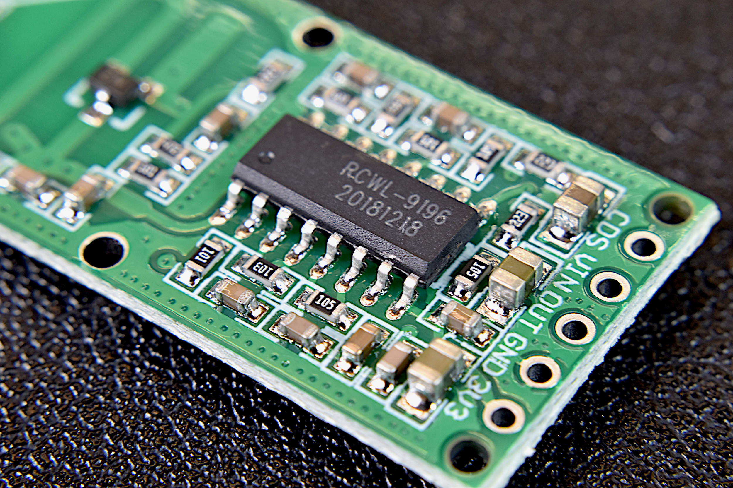
The RCWL-0516 is a non-contact motion sensor that is capable of detecting motion behind walls and enclosures by sending and receiving microwave pulses. Unlike passive infrared (PIR) sensors, the RCWL-0516 sensor tracks ALL object motion, including non-radiative objects. The RCWL0516 can also be used for highly stable object detection, much like an ultrasonic sensor or reflective IR sensor.
Included in the RCWL-0516 sensor package:
RCWL-0516 Microwave Sensor
Solder Pins
RCWL-0516 Sensor Specifications:
4V - 28V Supply Voltage
100 mA Peak Current Consumption
5m - 9m Motion Detection Range (default is 7m)
3.2 GHz Frequency
2s Re-Trigger Time
RCWL-0516 Datasheet can be found here

The MPU6050 is a 6-degree of freedom (DoF) inertial measurement unit (IMU) that measures acceleration in gravitational units (g) and angular velocity in degrees per second. The sensor has an onboard accelerometer and gyroscope that return 16-bit signed digital units, making the device fairly accurate for measuring rotation and accelerations in the three cardinal directions. The MPU6050 also measures temperature using an onboard temperature sensor.
The MPU6050 is fully compatible with Arduino and Raspberry Pi
Included in the MPU6050 sensor package:
MPU6050 Sensor
8-pin header
A tutorial using the MPU6050 IMU can be found on our site at: https://makersportal.com/blog/2019/8/17/arduino-mpu6050-high-frequency-accelerometer-and-gyroscope-data-saver
The ATGM336H GPS module is a tiny (13mm x 16mm) constellation positioning and navigation device that is capable of connecting with up to six satellites to approximation its geolocation on earth. The ATGM336H is a great low-profile alternative to the similar NEO-6M GPS module that is commonly used in the Arduino/Raspberry Pi sphere. The ATGM336H has an accuracy of 2.5m and is capable of updating its coordinates 1-10 times per second. The GPS module uses a serial protocol to communicate with the Arduino platform (similar to the NEO-6M). Many of the libraries that work with other GPS modules also work with the ATGM336H, making it a great replacement for projects that require smaller geometries or weigh very little.
Included in the ATGM336H GPS Module Package:
1x ATGM336H GPS Module
1x 5-Pin Header
1x External GPS Antenna
Features of the ATGM336H GPS Module:
Dimensions: 13mm x 16mm
2.7V - 3.6V Supply Voltage
Average Power Consumption: <25mA (@3.3V)
Communicates with: BeiDou Navigation Satellite Systems (BDS) and Global Navigation Satellite Systems (GNSS)
32 Tracking Channels
Reads up to six satellite navigation systems and implement joint positioning, navigation,
and timing.
2.5m Positioning Precision
~32s to First Fix
1Hz-10Hz Update Rate
Serial Baudrate: 9600 (default)
Operational Temperature Range: -40℃ to +85℃
Read the Datasheet

Included in Package:
K-Type Beaded Thermocouple
MAX31855 amplifier
Breakout pins and header
-Item Descriptions-
MAX31855 Amplifier:
-200C to 1350C Measurement Range
SPI interface
3V-5V DC Supply
Digital temperature output
14-bit resolution, 0.25 degree temperature resolution
Fully compatible with SPI-capable Arduino boards
K-Type Thermocouple:
-50°C to 204°C measurement range
±2°C error
The USB datalogger is a simple way to acquire high frequency data from the USB port of the Raspberry Pi computer. The USB sound card shown here, allows sample rates up to 48kHz. The USB datalogger is great for high frequency audio recording or high frequency vibration recording, particularly in the analog domain.
Included in the Raspberry Pi USB Datalogger Kit:
1x USB Datalogger
1x 3.5mm Terminal Breakout
Some Features of the USB Datalogger:
44.1kHz/48kHz Sample Rates
Single Channel Input
5V Maximum Input
Compatible with Analog Devices
High Frequency Datalogging
Terminal Breakout makes it easy to prototype

The MPU9250 is a 9 degree-of-freedom (9-DoF) inertial measurement unit (IMU). This incredible small profile sensor houses an accelerometer and gyroscope in the MPU6050 and a magnetometer in the AK8963. What an incredible combination for such a small device! The MPU9250 allows users to measure acceleration, angular velocity, magnetic inclination - all with the 2-wire I2C protocol.
Included in the MPU9250 Package:
1x MPU9250 IMU Board
10x Pin Header
Some Features of the MPU9250 IMU Board:
3-Axis Accelerometer (MPU6050)
±2g, ±4g, ±8g and ±16g with 16-bit ADC
~4000Hz Data Sample Rate
3-Axis Gyroscope (MPU6050)
±250, ±500, ±1000, and ±2000°/sec with 16-bit ADC
~8000Hz Max Data Sample Rate
3-Axis Magnetometer (AK8963)
±4800µT with 14-bit ADC
~ 8Hz-100Hz Data Sample Rate
I2C Communication Protocol
Low Power Consumption Options
Compatible with Arduino and Raspberry Pi
MPU9250 Datasheet
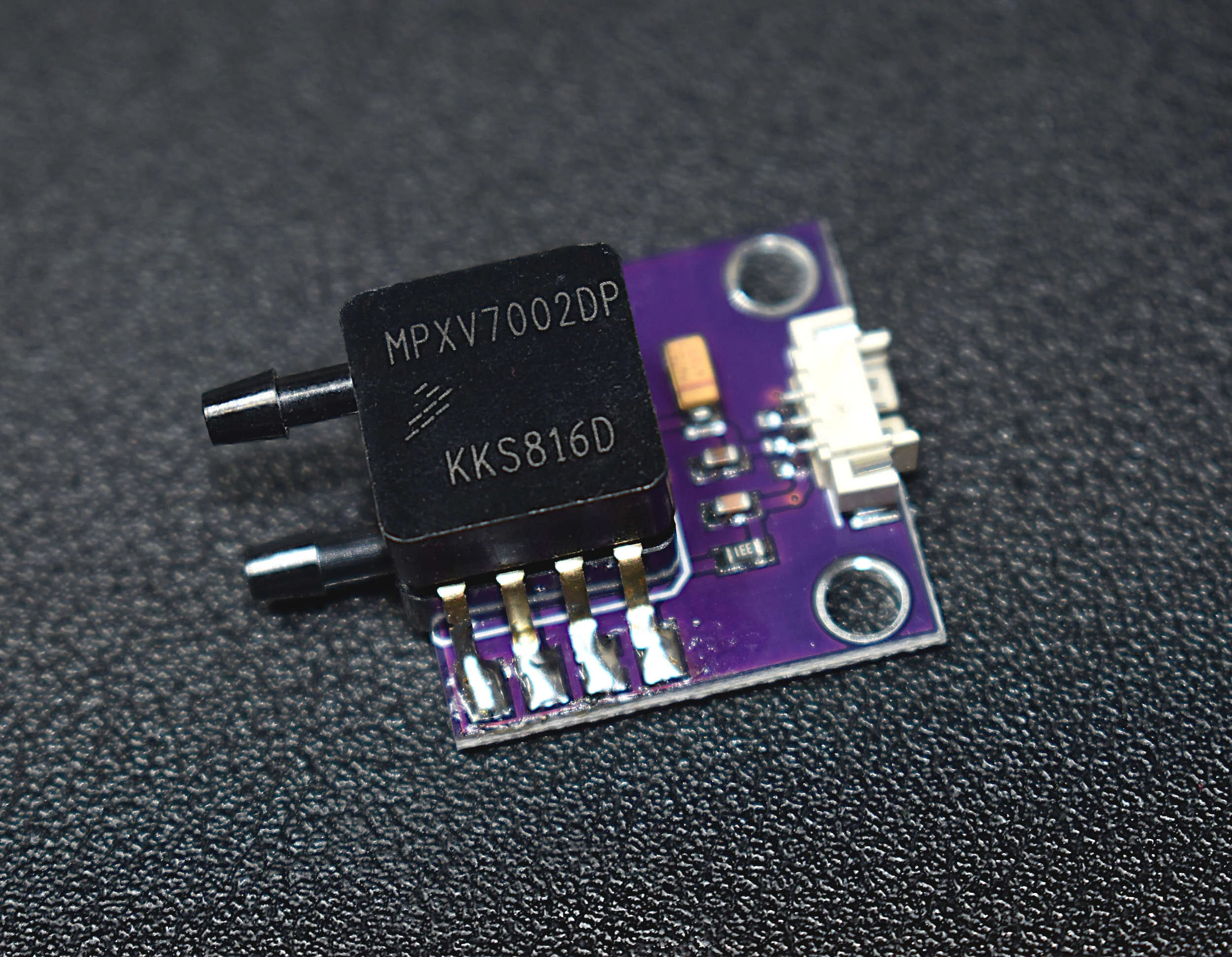
UPDATE: The supply chain for the MPXV7002DP is currently broken, thus we have developed a similar sensor called the XGMP3v3 Differential Pressure Sensor, which behaves in a similar manner as the MPXV7002DP.
The MPXV7002DP is a differential pressure sensor that is often paired with a pitot tube to measure the airspeed of drones and small aircraft. The MPXV7002DP can also be used to measure local pressures in pipes and enclosures where fluid is flowing, without the need for a pitot tube. The differential pressure sensor is also great for measuring the speed of enclosed flows over a venturi meter - where the area of the enclosure changes.
Included in the MPXV7002DP Package:
1x MPXV7002DP Differential Pressure Sensor
1x Breakout Cable (3-Pin)
Features of the MPXV7002DP Differential Pressure Sensor:
-2 kPa - +2 kPa Measurement Range
5V Supply Voltage
~0.1mA Power Consumption
1.0 V/kPa Sensitivity
1ms Response Time
Analog Output: 0.5V - 4.5V
2.5% Reading Error
75 kPa Maximum Pressure Tolerance (On each Port)
Fits best with 2.5mm Inner Diameter (I.D.) Tubing
Arduino/Raspberry Pi Compatible
Full Datasheet can be found here
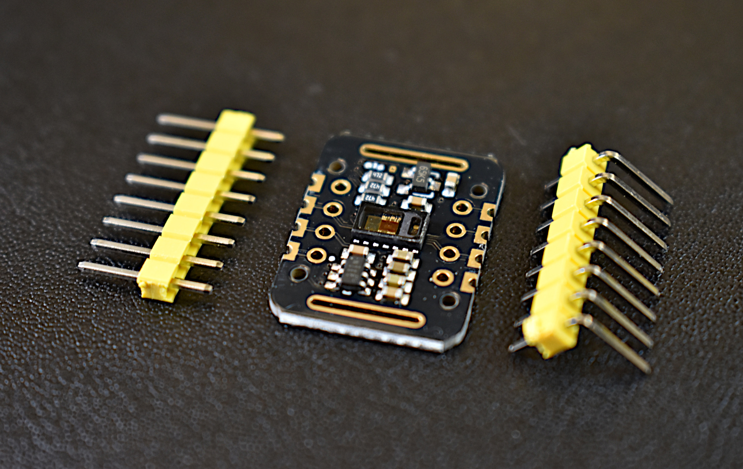
The MAX30102 module uses a red LED (660nm), infrared LED (880nm), and photodetector to approximate blood oxygen content and heart rate pulses. The sensor can be placed on a finger, wrist, or other area with significant blood flow to measure these parameters.
Included in the package:
MAX30102 Module
Solder Pins
Module Specifications:
3.3V-5V
6mA Max Consumption
50Hz - 3200Hz Sample Rate
18-bit ADC resolution
I2C Communication
Arduino Compatible
Module datasheet can be found here.

The HX711 is a 24-bit analog-to-digital converter that is compatible with Arduino and Raspberry Pi. The HX711 works in conjunction with a strain gauge load cell to approximate the mass of an object in real-time to high precision.
Included in this package:
1kg Load Cell
HX711 ADC
Features of the HX711:
2.7V-5.5V
24-bit resolution ADC
Slim profile
Libraries available for both Raspberry Pi and Arduino
The AMG8833 is a 64-pixel temperature sensor developed by Panasonic under the Grid-EYE® product line. The sensor contains an 8x8 array of infrared thermopiles, which approximate the temperature by measuring the infrared radiation being emitted from emissive bodies. The Grid-EYE communicates via the I2C bus, which also makes it compatible with Raspberry Pi and Arduino right out of the box. The AMG8833 contains an onboard lens that limits the viewing angle of the sensor to 60-degrees, which results in a sensing region useful for objects in the mid-field (as opposed to far-field or near-field). It also operates at 3.3V and 5V, at a sample rate of 1Hz-10Hz, with an approximate temperature resolution of 0.25°C over a range of 0°C to 80°C. The AMG8833 is useful for applications in thermal imaging, heat transfer analyses, human temperature monitoring, heating and air condition management, industrial control, and other applications in non-contact temperature measurement.
Included in the AMG8833 Thermal Camera Package:
1x AMG8833 Grid-EYE® 64-Pixel Infrared Array Module
1x 6-Pin Solder Header
Features of the AMG8833 Thermal Camera:
MEMS 64-Pixel Infrared Thermopile Array (8x8 Grid)
3.3V - 5.0V Supply Voltage
0℃ to 80℃ Measurement Range (at 0.25℃ Resolution)
± 2.5℃ Temperature Accuracy (Typical)
0.2mA to 4.5mA Current Consumption
1Hz - 10Hz Sample Rate Options
Operating Modes: Normal, Sleep, Interrupts (1s. 60s)
I²C Communication (SDA/SCL) [0x68 and 0x69 Selectable Address]
Onboard Thermistor (Ambient Temperature Sensing)
−20 ℃ to 80 ℃ Range
0.0625 ℃ Resolution
Compatible with Raspberry Pi and Arduino

The GY-91 is a 10 degree-of-freedom (DoF) inertial measurement unit (IMU). This incredible small profile sensor houses an accelerometer and gyroscope in the MPU6050, a magnetometer in the AK8963, and altitude (barometric pressure, temperature) sensor in the BMP280. What an incredible combination for such a small device! The GY-91 allows users to measure acceleration, rotation, magnetic inclination, altitude, and temperature - all with the 2-wire I2C protocol.
Included in the GY-91 (MPU9250 + BMP280) Package:
1x GY-91 IMU Board
8x Jumper Wires
Some Features of the GY-91 IMU Board:
3-Axis Accelerometer (MPU6050)
±2g, ±4g, ±8g and ±16g with 16-bit ADC
~4000Hz Data Sample Rate
3-Axis Gyroscope (MPU6050)
±250, ±500, ±1000, and ±2000°/sec with 16-bit ADC
~8000Hz Max Data Sample Rate
3-Axis Magnetometer (AK8963)
±4800µT with 14-bit ADC
~ 8Hz Data Sample Rate
Temperature and Pressure Transducer (BMP280)
-40 to +85 °C Temperature Range with 16-20 bit ADC
300 - 1100 hPa Pressure Range with 16-20 bit ADC
~150Hz Data Sample Rate
I2C Communication Protocol
Low Power Consumption Options
Compatible with Arduino and Raspberry Pi
The QuadMic Array is a 4-microphone array based around the AC108 quad-channel analog-to-digital converter (ADC) with Inter-IC Sound (I2S) audio output capable of interfacing with the Raspberry Pi. The QuadMic can be used for applications in voice detection and recognition, acoustic localization, noise control, and other applications in audio and acoustic analysis. The QuadMic can be connected to the header of a Raspberry Pi computer and used to record simultaneous audio data from all four of its microphones. Some applications of the QuadMic are: characterizing noise sources, room and spatial geometries, and other aspects of acoustic systems.
Included in the QuadMic 4-Microphone Array Package:
1x QuadMic 4-Microphone Array
Features of the QuadMic 4-Microphone Array:
Four SPU0414HR5H MEMS Microphones
100Hz - 10kHZ Flat (4dB) Frequency Response
16kHz Sample Rate for Each Microphone
I2S Audio Protocol
I2C Output Connector
GPIO 12/13 Available via Output Connector
12 Addressable RGB LEDs via SPI
Compatible with Raspberry Pi
Electronic Wiring Diagram can be found here
Read about the AC108 Analog-to-Digital Converter here
The MPS20N0040D is a gauge pressure transducer that approximates pressures from roughly -10kPa to +10kPa. The sensor uses an Hx710B 24-bit analog-to-digital converter (ADC) and signal amplifier to amplify the output from the MPS20N0040D to 0V - 5V. The response of the MPS20N0040D can be approximated using an Arduino board via 2-wire serial protocol.
Included in the MPS20N0040D Sensor Package:
1x MPS20N0040D Ported Pressure Sensor
2x Solder Pin Sets
Some Features of the MPS20N0040D Pressure Sensor:
5V Operating Voltage
-10kPa - 10kPa Measurable Pressure Range
+25mV DC Offset, 50mV Full Scale Output
Linear Response Between Voltage and Pressure
Compatible with 2.5mm Tubing
Arduino and Raspberry Pi Compatible
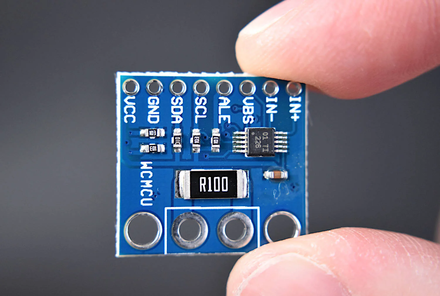
The INA226 is a current and voltage sensor that communicates via I2C and is capable of measuring both current and voltage at 16-bit resolution.
Included in the INA226 Voltage/Current Module Package:
1x INA226 Current Sensor
1x Terminal Block
1x 8-Pin Solder Header
Features of the INA226 Voltage/Current Sensor:
Senses Bus Voltages From 0V to 36V
2.7-V to 5.5-V Input Power Supply Range
I2C Communication (Raspberry Pi, Arduino, Pico-Compatible)
High-Side or Low-Side Sensing
16-bit Analog-to-Digital Converter
Current, Voltage, and Power Outputs
Low-Power Operation (330μA Quiescent Current)
NOTE: The terminal block overlaps slightly with the shunt resistor on the INA226, however, it does not affect the functionality of the sensor.
Included in the Package:
1x Raspberry Pi 5MP Camera
1x Ribbon Cable
NOTE: If a Raspberry Pi Zero is being used, select the RPi Zero from the dropdown menu below. If a longer cable is desired, select the standard cable with a longer length (only available for RPi 2,3,4; not Zero).
The Raspberry Pi camera is 5 megapixels in resolution and is fully compatible with Raspberry Pi 2B, 3, 3B, 3B+, and 4. It also works with the Zero and Zero W (with the correct ribbon cable). The picamera has a dedicated Python library that allows users to control the camera and take photos and record video. The library also allows users to control the white balance, shutter, and read each RGB pixel directly from the camera.
Some Features of the Picamera:
5MP Max photograph resolution (2592 x 1944 = 5,038,848 pixels)
Ribbon Cable that attaches directly to the Raspberry Pi
Pixel Size: 1.4 x 1.4 μm
Lens: f=3.6 mm, f/2.9
Viewing Angle: 54° x 41°
Max video resolution: 1080p @ 30fps
Max frame rate: 480p @ 90fps
Selectable video resolutions: 1080p @ 30fps, 720p @ 60fps, 480p @ 90fps
Sensor size: 3.67mm x 2.74mm (1/4" format)
Camera Module PCB dimensions: 25mm x 24mm (9mm thickness)
Documents on Python’s picamera library can be found here.
The USB microphone is perfect for audio projects that involve Raspberry Pi due to its slim profile, long attached USB cable, and its frequency response. This USB microphone can be used for acoustic signal processing, voice recognition, musical instrument recording, or engineering applications in machine noise monitoring.
Included in package:
USB Condenser Microphone
USB Microphone Specs:
1.5 m long cable
Omnidirectional response pattern
USB 2.0 (works with Raspberry Pi)
50 Hz - 16 kHz frequency response
Microphone Size (without windscreen): 6.5 cm x 0.7 cm
44.1 kHz/48kHz USB Sample Rate Selection
-38 dB ± 3 dB Sensitivity
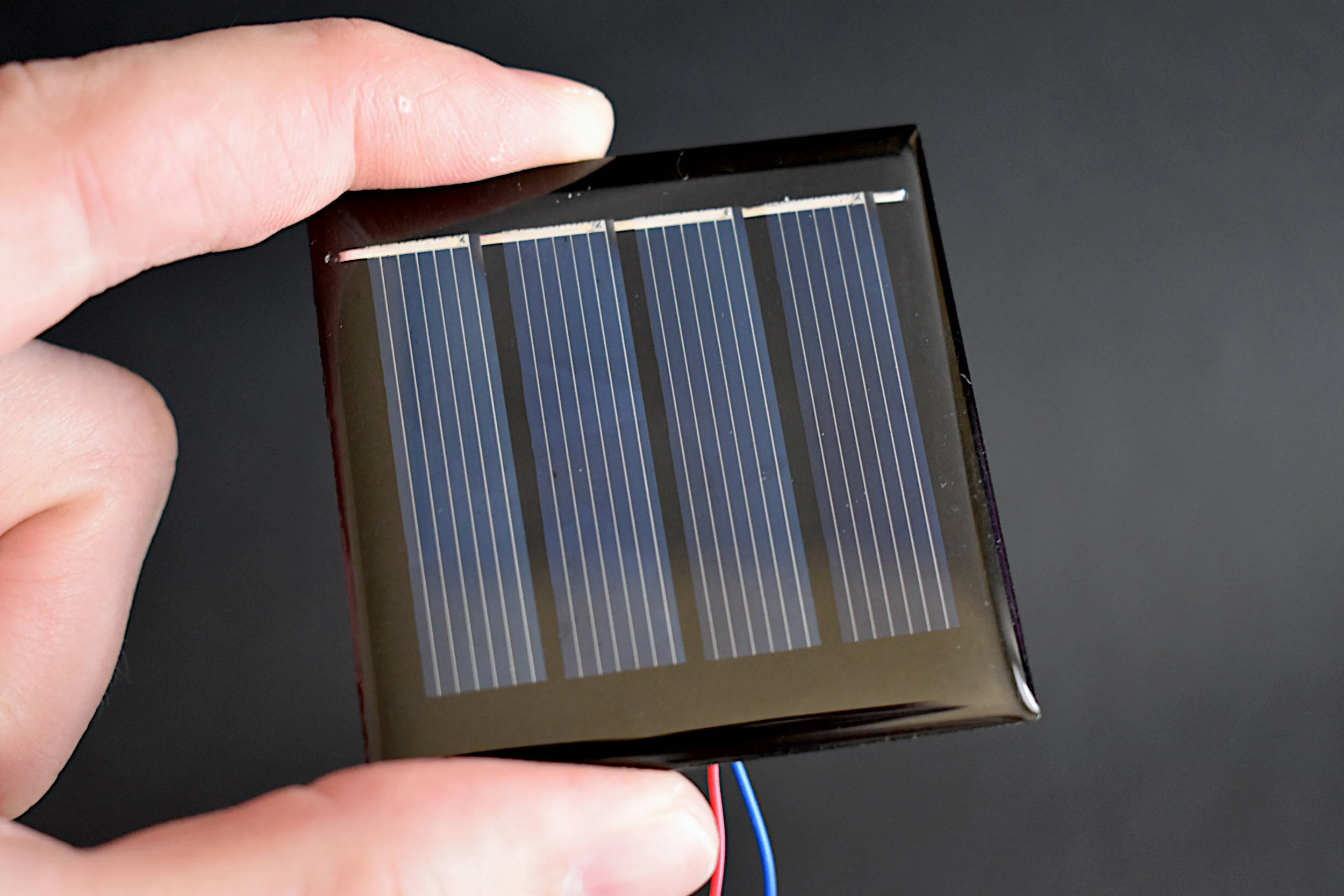
Solar panels are essential to understanding solar power and how engineers generate power using the sun. Photovoltaic cells, commonly referred to as PV cells, are at the center of all solar panels and are responsible for the conversion of solar energy into electricity. The study and theory of photovoltaic power production is quite complex and involves understanding the relationship between voltage and current generated by solar energy incident on a given solar panel and impacted by electronics present in the equivalent solar circuit. The solar panel given here generates roughly 200mW at 1.6V at peak solar insolation. It is ideal for low-power projects and testing and learning about solar energy conversion.
Included in the Solar Panel Power Metering Kit:
1x 200mW Solar Panel [Wire Colors May Vary]
Features of the 200mW Solar Panel:
54mm x 54mm Physical Dimensions (4 cells at 10mm x 38mm Active Area)
200mW Peak Power Output @ 1.65V [see tutorial for experiment]
2.14V Open-Circuit Voltage
123mA Short Circuit Current
1.6V Max Power Voltage
120mA Max Power Current
Epoxy Finish (Waterproof Cells, not Electronics)
Soldered Dupont Breakout Wires (Lengths and Colors may Vary)
See Plot Below for IV Curve
The Maker Portal Uno board is the centerpiece of many of the projects carried out in our maker spaces. The Uno board is capable of reading a wide range of sensors using analog-to-digital conversion, SPI, I2C, UART, and other common protocols. The Uno board can be used to control motors, OLED/LCD displays, and LEDs. The Arduino Uno board shown here is the official Maker Portal microcontroller, which we use in many of our projects!
Included in the Arduino Uno Package:
Maker Portal Arduino Uno Rev3 Board
Black USB Cable (1m in Length)
Specifications for Arduino Uno Rev3 Board:
ATmega328P chip with Arduino Bootloader
14 digital pins, 6 analog pins
10-bit analog-to-digital converter (ADC)
5V-12V Supply Tolerance
3.3V and 5.0V output pins
16 MHz clock
5 PWM pins, I2C support, SPI support , UART support
ATmega16U2 USB TTL, compatible with Linux, Windows, and Mac
Black Stylish Finish
Fully Integrated with Arduino IDE software

In the Package:
D1 Mini ESP8266 WiFi Module
Pins for Soldering
Product Specifications:
ESP8266 chipset
CH340 USB converter onboard (compatible with Raspberry Pi)
1 analog input
11 digital I/O
Works with many Arduino libraries
The ESP32 chip is a hybrid Bluetooth + WiFi-enabled microcontroller developed by Espressif Systems, the same developer as the widely popular ESP8266 WiFi-enabled microcontroller. The ESP32 board shown here is in a compact D1 Mini profile, which makes its geometry similar to their ESP8266 D1 Mini boards and other smaller Arduino boards. The ESP32 is fully compatible with the Arduino IDE and has a wide array of examples that allow users to get started with Bluetooth Classic, Bluetooth Low Energy (BLE), and WiFi servers and clients. The microcontroller has a fast CPU (240MHz), 12-bit ADC, peripheral communication (UART, SPI, I2C), and a wide array of GPIO pins. The ESP32 D1 Mini is a great choice for IoT applications.
Included in the ESP32 D1 Mini Package:
1x ESP32 D1 Mini Board
4x Female Dupont Pins (short), 2x Female Dupont Pins (long)
1x Micro USB Cable
Features of the ESP32 D1 Mini Bluetooth+WiFi Board:
Supply Voltage: 3.0 V ~ 3.6 V (VCC), 3.0V - 5.0V (USB and 5V)
Operating Voltage: 3.3V (GPIO pins)
Power Consumption:
30mA - 80mA (idle)
100mA - 240mA (WiFi/Bluetooth RX/TX)
10µA - 150µA (Deep Sleep)
5µA (RTC Timer Only)
Peripheral Interfaces: UART, SPI, I2C, LED PWM, Motor PWM, I2S, IR, pulse counter, GPIO, capacitive touch sensor, ADC, DAC
WiFi - 802.11 b/g/n (802.11n up to 150 Mbps) @2.4 GHz ~ 2.5 GHz
Bluetooth - Bluetooth v4.2 BR/EDR and BLE specification
Operating Temperature: –40 °C ~ +85 °C
40 Available GPIO Pins
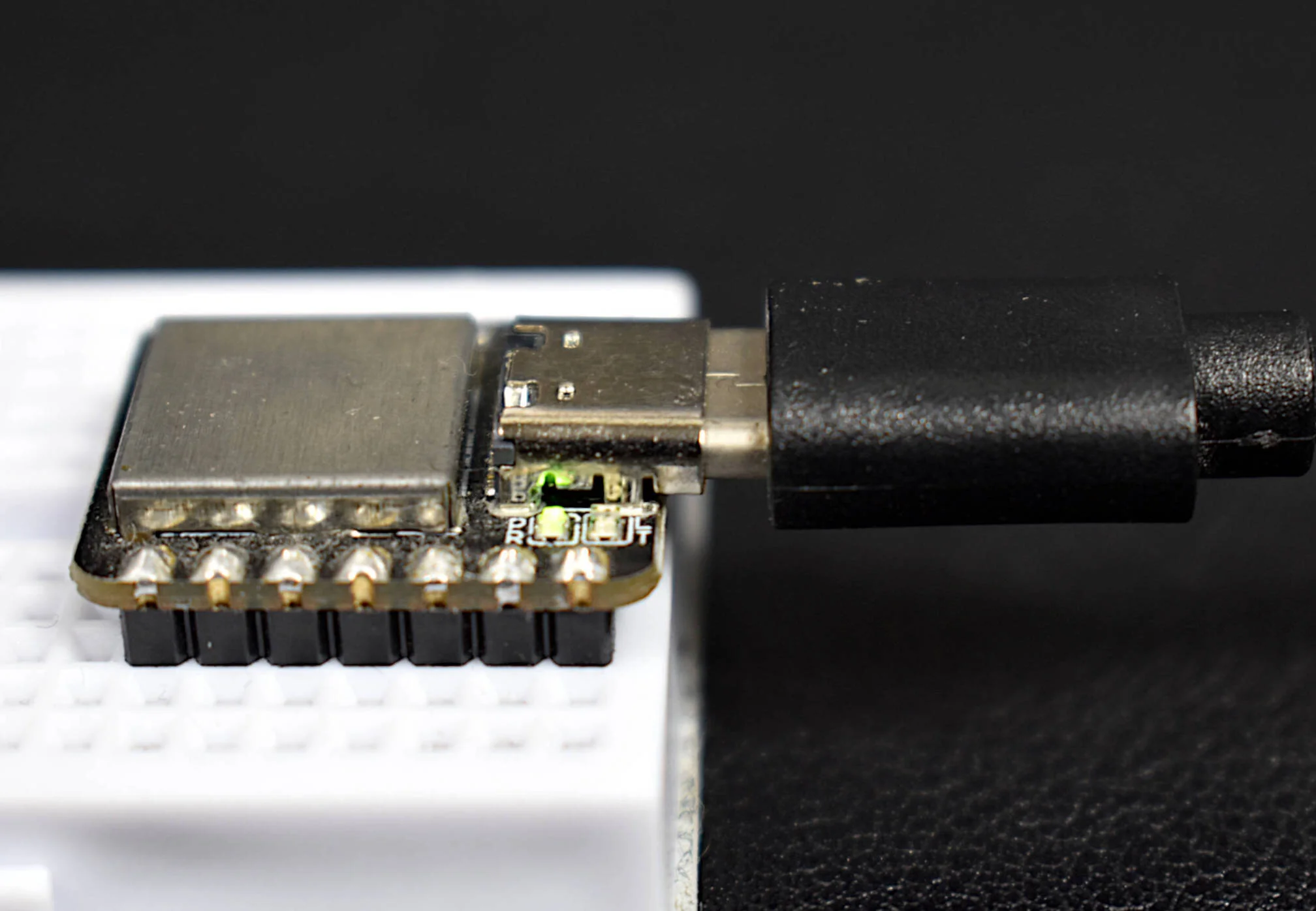
The Arduino Xiao is the perfect microcontroller for applications where a small board profile is required in conjunction with high processing power. The ATSAMD21 is at the center of the Arduino Xiao, which is a low-power, 32-bit Arm® Cortex® -M0+ CPU running at 48 MHz. The 48MHz processor speed is 3x faster than traditional 8-bit Arduino board (ATmega328-based) which run at 16MHz. The Arduino Xiao is a great selection for projects involving wearable devices, audio processing, Internet of Things (IoT) applications, and general rapid prototyping.
Included in the Arduino Xiao Package:
1x Arduino Xiao (14-Pin ATSAMD21G18 Microcontroller)
2x 7-Pin Header
Black USB-C Cable (1m)
Features of the Arduino Xiao (ATSAMD21):
3.3V Operating Voltage, 5.0V Input and Power Pin
32-bit, 48 MHz Arm® Cortex® -M0+ CPU
256KB Flash Memory, 32KB SRAM Memory
Idle and Stand-by Sleep modes (with peripherals)
Serial Communication Interfaces (SERCOM):
UART, SPI, I2C, LIN
Inter-IC Sound (I2S) Interface
12-bit Analog-to-Digital Converter (ADC)
10-bit Digital-to-Analog Converter (DAC)
General Purpose Input/Output Pins (GPIO)
ATSAMD21 datasheet

This Arduino Nano board is paired with a Bluetooth Low Energy (BLE) chip that makes it both an Arduino board and a BLE-enabled device. The BLE-Nano has all the functionality of an ATmega328P microcontroller (Arduino Nano) while also having an integrated BLE chip wired to its serial pins. This means that many of your Arduino projects can be Bluetooth-enabled with just a few lines of code and the BLExAR app!
NOTE: Due to supply chain issues, the BLE-Nano has been discontinued from our store. Please see the MakerBLE Arduino Board as an improvement and alternate.
Included in the BLE-Nano Package:
1x Soldered BLE Nano Board (ATmega328P + CC2540)
1x Black Micro USB Cable
Some Features of the BLE-Nano Arduino Board:
ATmega328P Microcontroller
Arduino Nano Bootloader
Operating Voltage: 5V (Input: 5V - 12V)
16 MHz Clock Speed
Available I/O Pins: 12 Digital, 8 Analog
6 Digital PWM Pins
Current Usage: 19 mA
Profile: 48 x 19mm
Weight: 7 g
Arduino IDE Compatible
CC2540 Bluetooth Low Energy Chip
Serial Communication with Nano (pins 0/1)
2.4 GHz Bluetooth Communication
Compatible with BLExAR iOS App
Onboard Antenna

Included in Package:
SAMD21 M0 Mini 32-bit Microcontroller
Solder Pins
The SAMD21 core is a 32-bit microcontroller that will likely replace the traditional ATmega328 (8-bit microcontroller) over time. The SAMD21 core boasts 48MHz clock speeds in contrast to the 20MHz ATmega boards, while also being fully-compatible with many of the capabilities of the Arduino platform. The SAMD21 boards incorporate a multitude of upgrades including: higher analog-to-digital resolution (12-bit over 10-bit), 10-bit digital-to-analog conversion (DAC), an on-board USB converter (compatible with Mac, Windows, and Linux), a two channel I2S interface, and much more! The SAMD21 is also compatible with many of the sensor libraries in Arduino that function with I2C communication, SPI communication, and other serial communications - which is essential for introducing the SAMD21 as an upgraded Arduino board used in conjunction with the myriad of examples and applications already available on the platform.
Features of SAMD21 M0 Mini:
5V USB Power Input
3.3V, 180mA I/O Ratings
48MHz clock frequency
25 GPIO pins
12 PWM pins
6 12-bit analog I/O pins
1 Digital to Analog Converter (DAC)
32-bit ARM Cortex® M0+ core
I2C, SPI, I2S compatible
Widely compatible with the Arduino platform

The ATtiny85 can be used as a small Arduino board that is capable of 10-bit analog-to-digital conversion, control of 6 of its digital pins, and voltage tolerances of 2.7-5.5V - all of which allow it to work under very low power electronics and internet of things applications. The microcontroller current consumption ranges from: 5mA, 1.2mA, 10uA under active/idle/power down conditions (8MHz). It also has a serial interface, which allows it to be programmed by another Arduino board, making it the perfect tiny microcontroller where larger Arduino boards may be too large.
Included in Package:
ATtiny85 AVR Microcontroller
Features of the ATtiny85:
10-bit ADC
4 Possible Analog Inputs
6 Possible Digital Pins
2.7-5.5V Tolerance
5mA, 1.2mA, 10uA Active/Idle/Power Down Current Consumption (8MHz)
Serial Interface
Interrupt Capabilities
Internal Crystal Oscillators (1MHz, 8MHz)
The ATtiny85 datasheet can be found [here].
A tutorial that uses the ATtiny85 as an Inernet of Things (IoT) board can be found here.
The Raspberry Pi Pico is a new microcontroller designed by the Raspberry Pi foundation. The Pico is a groundbreaking board that is meant to use MicroPython in its native micro USB port. The RP2040 is the microcontroller chip at the center of the Pico, which has a dual-core Arm Cortex M0+ processor, capable of clocking at 133 MHz, which is much faster than many of the Arduino boards currently on the market. The Pico has GPIO pins and interfaces such as: SPI, UART, I2C, PWM, and a 12-bit analog-to-digital converter (ADC). This Raspberry Pi Pico Kit comes with the Pico microcontroller, an RGB LED, a breadboard, jumper wires, and USB cable.
Included in the Raspberry Pi Pico Starter Kit:
1x Raspberry Pi Pico Board
2x 20-pin Headers
1x Black 0.5m Micro USB Cable
1x RGB LED
4x Male-to-Male Jumpers
1x Half Breadboard (White)
Features of the Raspberry Pi Pico:
1.8V - 5.5V Input Voltage
21 mm × 51 mm Board Geometry
RP2040 microcontroller
Dual-core Arm Cortex-M0+ processor (Clock Speed up to 133 MHz)
264KB on-chip SRAM, 2MB on-board QSPI Flash
26x GPIO pins (3x 12-bit Analog Inputs)
2x UART, 2x SPI, 2x I2C, 16x PWM
1x USB 1.1 controller and PHY, with host and device support
8x Programmable I/O (PIO) state machines for custom peripheral support
Operating temperature -20°C to +85°C
Low-power sleep and dormant modes
Onboard Temperature sensor
Accelerated integer and floating-point libraries on-chip
NOTE: Our batch of RGB LED modules have reversed labels for green and red, meaning, the label R is for green, and G is for red. This was noticed after receiving and testing the modules from our manufacturer.

The Atmega328P is at the center of every Arduino Uno board and acts as the 8-bit microcontroller that controls and interacts with sensors, motors, relays, and other electronic devices. The ATmega328P-U shown here is a dual in-line package microchip that can be placed on a breadboard, making it ideal for projects that require enclosure, or prototypes moving beyond the development board phase. The ATmega328P-U is also a great selection for Internet of Things (IoT) development, as its inherent power consumption is very low without LEDs or regulators.
Included in the ATmega328P-U Package:
1x ATmega328P-U with Arduino Bootloader
Some Features of the ATmega328P-U:
28-Pins in a Dual In-Line Packaging (2x14 pins)
Capabilities: SPI, I2C, USART, PWM
2.7V - 5.5V Input Voltage Range
1µA - 1.5mA Power Consumption (3V)
10-bit Analog-to-Digital Converter (8-channels)
Interrupt Capabilities (2-channel)
32KB of Flash Memory for Programming
0MHz-16MHz Frequency Capabilities (External Crystals)
8-bit/16-bit Timers
Compatible with Arduino IDE

The MakerBLE board is a Bluetooth Low Energy (BLE) microcontroller development board based on Nordic’s nRF52840 chip. The MakerBLE acts as an Arduino board and a BLE-enabled device. It has much of the functionality of classic Arduino boards, while also having an integrated BLE chip capable of communicating via BLE 5.0. This means that many Arduino projects can be Bluetooth-enabled with just a few lines of code and the BLExAR app!
→ Getting Started Tutorial for MakerBLE Board ←
Included in the MakerBLE Package:
1x MakerBLE Board
2x 7-Pin Header
1x Black USB-C to USB2.0 Cable (1m long)
Some Features of the MakerBLE Board:
Arduino Bootloader
Nordic nRF52840, ARM® Cortex™-M4 32-bit processor with FPU operating at 64 MHz
3.3V Operating Voltage and Logic
3.3V-5V Input voltage (3.7V LiPo Battery Compatible)
Ultra-low sleep power: 5 μA, deep sleep model
Wireless capabilities: Bluetooth 5.0, NFC, and ZigBee module with onboard antenna
Multiple Peripherals: 1x Reset button, Ix UART, 1x IIC, 1x SPI, 1x NFC, 1x SWD, 11x GPIO, 6x ADC, 1x Three-in-one LED,1x User LED
Onboard 2 MB flash
Single-sided components, surface mounting design (low profile)
14 Available I/O Pins: 11 Digital, 6 Analog
Physical Dimensions: 21mm x 17.5mm
Weight: 3 g (Unsoldered), 5g (Soldered)
Arduino IDE Compatible
GitHub Repository with example scripts and projects

Included in Package:
Arduino Uno Rev3 Board with ATmega16U2 TTL Converter
USB 2.0 Cable
Specifications for Arduino Uno Rev3 Board:
ATmega328P removable chip
14 digital pins, 6 analog pins
5V-12V Supply Tolerance
3.3V and 5.0V output pins
16 MHz clock
5 PWM pins, I2C support, SPI support , UART support
ATmega16U2 USB TTL, compatible with Linux, Windows, and Mac
Black Stylish Finish
NOTE: This is not a genuine Arduino Company board but functions exactly the same
Compatible with Arduino IDE software

Included in Package:
1x NEO-6M GPS Module (GY-GPS6MV2)
1x Ceramic Antenna
1x 4-Pin Solder Pin Header
Module Description:
Power Supply: 3V-5V
EEPROM
LED Indicator
Backup battery
Baud Rate: 9600
Mounting Holes: 3mm
Module Dimensions: 23mm x 30mm
Antenna Dimensions: 25mm x 25mm
Antenna Cable Length: 50mm
Arduino UART Compatible
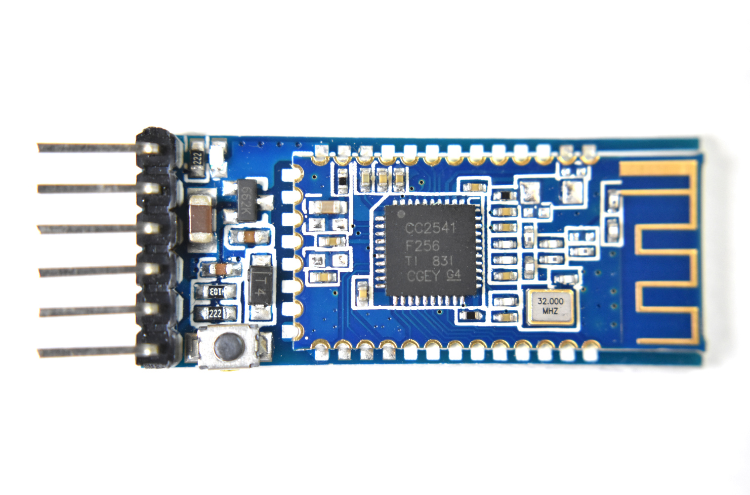
The CC2541 Bluetooth Low Energy (BLE) module is fully compatible with Arduino, Raspberry Pi, and Jetson Nano via serial port communication. The CC2541 works with both Android and iOS smartphones, making it a great choice when getting started with IoT prototyping and development. Multiple CC2541 modules can also be used as iBeacons that permit indoor tracking and localization.
Included in the Bluetooth Low Energy CC2541 Module Package:
1x CC2541 Bluetooth Low Energy Module
Features of the CC2541 Bluetooth Low Energy Module:
Wide Supply-Voltage Range (3.6 V - 5V)
Active-Mode RX Down to: 17.9 mA
Active-Mode TX (0 dBm): 18.2 mA
Power Down Sleep Mode: 60uA
Serial Communication (Arduino/Raspberry Pi Compatible)
Full datasheet can be found at Texas Instrument’s website: http://www.ti.com/lit/ds/symlink/cc2541.pdf
Examples can be found on our blog:
The ATGM336H GPS module is a tiny (13mm x 16mm) constellation positioning and navigation device that is capable of connecting with up to six satellites to approximation its geolocation on earth. The ATGM336H is a great low-profile alternative to the similar NEO-6M GPS module that is commonly used in the Arduino/Raspberry Pi sphere. The ATGM336H has an accuracy of 2.5m and is capable of updating its coordinates 1-10 times per second. The GPS module uses a serial protocol to communicate with the Arduino platform (similar to the NEO-6M). Many of the libraries that work with other GPS modules also work with the ATGM336H, making it a great replacement for projects that require smaller geometries or weigh very little.
Included in the ATGM336H GPS Module Package:
1x ATGM336H GPS Module
1x 5-Pin Header
1x External GPS Antenna
Features of the ATGM336H GPS Module:
Dimensions: 13mm x 16mm
2.7V - 3.6V Supply Voltage
Average Power Consumption: <25mA (@3.3V)
Communicates with: BeiDou Navigation Satellite Systems (BDS) and Global Navigation Satellite Systems (GNSS)
32 Tracking Channels
Reads up to six satellite navigation systems and implement joint positioning, navigation,
and timing.
2.5m Positioning Precision
~32s to First Fix
1Hz-10Hz Update Rate
Serial Baudrate: 9600 (default)
Operational Temperature Range: -40℃ to +85℃
Read the Datasheet

Included in Package:
E32-915TXXD LoRa Module
Antenna
Features of E32-915T20D LoRa Module:
3.3V - 5V Supply
120mA TX Current, 14mA RX Current, 4μA Sleep Current
Data Rates configurable from 0.3kbps - 19.2kbps
Operating Frequency 900MHz-931MHz (fully permitted in USA)
Open Air Distance ~3km
TX Power ~20dBm, RX Sensitivity ~-146dBm
UART TTL Serial Protocol
Based on SX1276 LoRa IC
Fully Compatible with Arduino boards over Serial UART Communication
E32-915T20D Full Datasheet here
In the Package:
D1 Mini ESP8266 WiFi Module
Pins for Soldering
Product Specifications:
ESP8266 chipset
CH340 USB converter onboard (compatible with Raspberry Pi)
1 analog input
11 digital I/O
Works with many Arduino libraries
The TinyBlueX is a combination module that contains an ATtiny85 microcontroller and CC254x Bluetooth Low Energy chip that is compatible with Arduino and the BLExAR iOS app. The TinyBlueX is very low power and low profile, which makes it great for simple internet of things (IoT) applications. The TinyBlueX can read sensors and transmit the data back to an iOS device. The TinyBlueX can also be controlled using the BLExAR app to turn LEDs, motors, and actuators on and off using the ATtiny’s GPIO pins. Pins 2,3,7 are available on the module, allowing the user to control/read up to three different devices or sensors.
Included with the TinyBlueX Module:
1x TinyBlueX Module
1x ATtiny85 Microcontroller
1x CC254x Bluetooth Low Energy Module
8x Female-to-Male Jumper Wires
Features of the TinyBlueX Module:
Dimensions: 56mm x 35mm x 18mm (Assembled)
Arduino IDE Compatible (Arduino as ISP Required)
Removable ATtiny85 Microcontroller and BLE Module
3.6V - 5.5V Supply Voltage Range
Bluetooth Low Energy Communication
Compatible with BLExAR iOS App
3x Analog Input Pins (10-bit) [Pins 2,3,7]
3x General Purpose Input/Output (GPIO) Pins [Pins 2,3,7]
1x External Interrupt Pin [Pin 7]
0MHz - 10MHz @ 3.6V-5.5V, 0MHz - 20MHz @ 4.5V - 5.5V
Low Power Modes with Watchdog Timer
The ESP32 chip is a hybrid Bluetooth + WiFi-enabled microcontroller developed by Espressif Systems, the same developer as the widely popular ESP8266 WiFi-enabled microcontroller. The ESP32 board shown here is in a compact D1 Mini profile, which makes its geometry similar to their ESP8266 D1 Mini boards and other smaller Arduino boards. The ESP32 is fully compatible with the Arduino IDE and has a wide array of examples that allow users to get started with Bluetooth Classic, Bluetooth Low Energy (BLE), and WiFi servers and clients. The microcontroller has a fast CPU (240MHz), 12-bit ADC, peripheral communication (UART, SPI, I2C), and a wide array of GPIO pins. The ESP32 D1 Mini is a great choice for IoT applications.
Included in the ESP32 D1 Mini Package:
1x ESP32 D1 Mini Board
4x Female Dupont Pins (short), 2x Female Dupont Pins (long)
1x Micro USB Cable
Features of the ESP32 D1 Mini Bluetooth+WiFi Board:
Supply Voltage: 3.0 V ~ 3.6 V (VCC), 3.0V - 5.0V (USB and 5V)
Operating Voltage: 3.3V (GPIO pins)
Power Consumption:
30mA - 80mA (idle)
100mA - 240mA (WiFi/Bluetooth RX/TX)
10µA - 150µA (Deep Sleep)
5µA (RTC Timer Only)
Peripheral Interfaces: UART, SPI, I2C, LED PWM, Motor PWM, I2S, IR, pulse counter, GPIO, capacitive touch sensor, ADC, DAC
WiFi - 802.11 b/g/n (802.11n up to 150 Mbps) @2.4 GHz ~ 2.5 GHz
Bluetooth - Bluetooth v4.2 BR/EDR and BLE specification
Operating Temperature: –40 °C ~ +85 °C
40 Available GPIO Pins
This Arduino Nano board is paired with a Bluetooth Low Energy (BLE) chip that makes it both an Arduino board and a BLE-enabled device. The BLE-Nano has all the functionality of an ATmega328P microcontroller (Arduino Nano) while also having an integrated BLE chip wired to its serial pins. This means that many of your Arduino projects can be Bluetooth-enabled with just a few lines of code and the BLExAR app!
NOTE: Due to supply chain issues, the BLE-Nano has been discontinued from our store. Please see the MakerBLE Arduino Board as an improvement and alternate.
Included in the BLE-Nano Package:
1x Soldered BLE Nano Board (ATmega328P + CC2540)
1x Black Micro USB Cable
Some Features of the BLE-Nano Arduino Board:
ATmega328P Microcontroller
Arduino Nano Bootloader
Operating Voltage: 5V (Input: 5V - 12V)
16 MHz Clock Speed
Available I/O Pins: 12 Digital, 8 Analog
6 Digital PWM Pins
Current Usage: 19 mA
Profile: 48 x 19mm
Weight: 7 g
Arduino IDE Compatible
CC2540 Bluetooth Low Energy Chip
Serial Communication with Nano (pins 0/1)
2.4 GHz Bluetooth Communication
Compatible with BLExAR iOS App
Onboard Antenna
The MakerBLE board is a Bluetooth Low Energy (BLE) microcontroller development board based on Nordic’s nRF52840 chip. The MakerBLE acts as an Arduino board and a BLE-enabled device. It has much of the functionality of classic Arduino boards, while also having an integrated BLE chip capable of communicating via BLE 5.0. This means that many Arduino projects can be Bluetooth-enabled with just a few lines of code and the BLExAR app!
→ Getting Started Tutorial for MakerBLE Board ←
Included in the MakerBLE Package:
1x MakerBLE Board
2x 7-Pin Header
1x Black USB-C to USB2.0 Cable (1m long)
Some Features of the MakerBLE Board:
Arduino Bootloader
Nordic nRF52840, ARM® Cortex™-M4 32-bit processor with FPU operating at 64 MHz
3.3V Operating Voltage and Logic
3.3V-5V Input voltage (3.7V LiPo Battery Compatible)
Ultra-low sleep power: 5 μA, deep sleep model
Wireless capabilities: Bluetooth 5.0, NFC, and ZigBee module with onboard antenna
Multiple Peripherals: 1x Reset button, Ix UART, 1x IIC, 1x SPI, 1x NFC, 1x SWD, 11x GPIO, 6x ADC, 1x Three-in-one LED,1x User LED
Onboard 2 MB flash
Single-sided components, surface mounting design (low profile)
14 Available I/O Pins: 11 Digital, 6 Analog
Physical Dimensions: 21mm x 17.5mm
Weight: 3 g (Unsoldered), 5g (Soldered)
Arduino IDE Compatible
GitHub Repository with example scripts and projects
Analog joysticks can be found in video game controllers, drone and remote-controlled vehicle controllers, and heavy machinery controllers. They’re great for just about any precision control project where human interfacing is desired. The analog joystick here is one that is compatible with both Arduino and Raspberry Pi - and is a great tool for learning coding, robotic control, and functional interaction between humans and computers.
Included in the Analog Joystick Package:
1x Analog Joystick Controller
5x Female-to-Male Jumper Wires
Some Features of the Analog Joystick:
5V Input Supply
2-D Rotational + 1-D Push Analog Responses
360° Rotation in 2-D Plane
Rubber Joystick Finish for Gripping
Smooth Rotation
Clicking sound for Push Notification
Compatible with Raspberry Pi + Arduino
Code for measuring joystick rotations can be found at this tutorial:

The MG90S Micro Servo is a 13g servo motor that is great for applications in low-cost robotics and automation. The MG90S can be powered directly from any 5.0V Arduino board, and can be controlled using the servo library included in most Arduino IDEs.
Included with the MG90S Micro Servo Package:
1x MG90S Micro Servo
1x Set of horns and screws (6 pcs)
3x Jumper Wires (Male-to-Male)
Some Features of the MG90S:
Input Voltage: 4.8V - 6.0V
Operating Current (5.0V): ~2.7mA (idle), ~70mA (no load), ~400mA (Stall)
Rotation Angle: 0° - 180° (Resolution: 1°)
Max Speed (5.0V): 0.6 deg/ms (full 180 degrees in 300 ms)
Largest Dimensions: 12mm x 32.5mm x 32.5mm
MG90S Datasheet
NOTE: These are not genuine Tower Pro motors
A full tutorial with the MG90S, including code and general working principles, is given here.

Electrical energy can be converted to magnetic energy through Ampere’s law by sending current through a coiled wire. The resulting device, called an electromagnet, uses electricity to create a temporary magnet that is capable of holding a specific amount of weight that can be calculated based on the number of coil windings, length and spacing of the coil, and input electrical current. Electromagnets are used in application ranging from: simple motors, relay switches, loudspeakers and headphones, junk yards, and scientific equipment. The electromagnet presented here is great for contactless control and movement with drones or robotic arms.
Included with the 10N Electromagnet Module:
1x 10N Electromagnet Module
3x Female-to-Male Jumper Wires
Some Features of the 10N Electromagnet:
3.3V - 5V Input Voltage
10N Holding Force
Compatible with Raspberry Pi and Arduino
3-Pin Power/GND/Signal Breakout
Low Power Consumption
The NEMA 17 stepper motor (Model: 17HS4023) is a powerful motor capable of microstepping, high-speed rotation, and high-torque holding. The stepper motor kit also includes a DRV8825 stepper driver and motor bridge, which makes getting started with motor driving easy. With the stepper bridge, only a Raspberry Pi or Arduino, 12V supply, and five jumper wires are needed to control the NEMA 17 stepper motor. This stepper kit can be used in applications involving 3D printers, DIY CNC machines, precise camera movement, LiDAR rotation, among others!
Included in the NEMA 17 Stepper Motor Kit:
1x NEMA-17HS4023 Stepper Motor
1x DRV8825 Stepper Driver with Heat Sink
1x DRV8825 Driver Bridge
5x Female-to-Female Jumper Wires
1x Stepper-to-Bridge Connector Wire
Features of the NEMA-17HS4023 Motor:
42mm x 42mm x 23mm (LxWxH - Approximate Dimensions)
Micro-stepping down from 1.8° down to 0.05625°
Wide Voltage Supply Range: 5V - 24V
0.7A - 1.0A per phase (2-phases total)
130g Weight
13 N·cm Holding Torque
Clockwise and Counterclockwise Rotation
Rotation speeds at 1.8° Increments up to ~500RPM (12V, no load), ~1800RPM (24V, no load)
Controllable via Arduino or Raspberry Pi
Tutorial on the NEMA 17 Kit here

These vibration motors are great for testing haptic feedback with Arduino and Raspberry Pi. The voltage, ground, and PWM pinouts make it easy to get started with vibration feedback. This module starts vibrating at 3.7V, thus it should be used with a 5V system.
Included with the Vibration Motor:
1x Vibration Motor Module for Arduino
Features of the Vibration Motor:
5V Voltage Rating
60mA - 90mA Power Consumption
Dimensions:
10mm (Radius of Vibration Motor)
21mm x 23mm (PCB)
21mm x 28mm (PCB w/Pins)
PWM Controlled
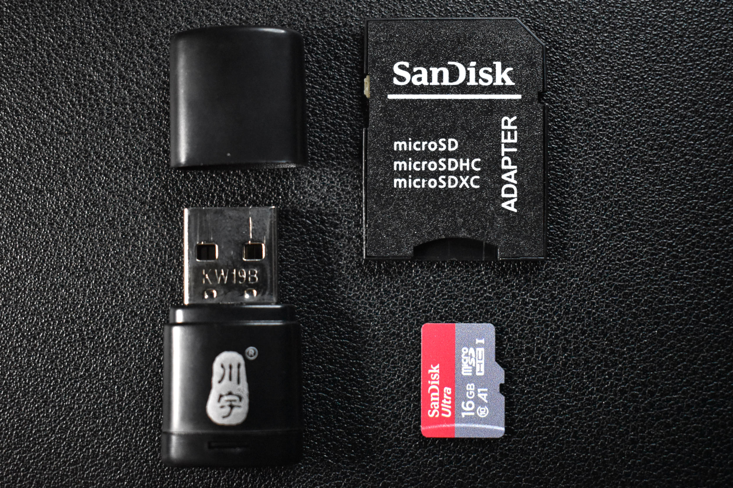
Included in Package:
16GB or 32GB Micro SD Card
Micro SD to SD Card Adapter
Micro SD USB Reader
The micro SD card and its adapters are great for use with the Arduino-compatible Micro SD Module, when portable data acquisition is desired.
Features of the Micro SD Card Kit:
16GB to 32GB of storage (slightly less in practice)
Read speeds up to 98 MB/s
write speed: 10 MB/s (class 10)
microSDHC
USB 2.0 adapter works with Raspberry Pi, Mac, Windows
Micro SD is compatible with Arduino SD writer/reader module

The SSD1306 display is an organic light emitting diode (OLED) device that is great for small-scale Arduino, Raspberry Pi, and Raspberry Pi Pico projects that involve real-time data acquisition, communication, and debugging. The display allows users to visualize and print out information related to sensors and modules — specifically when creating internet of things (IoT) nodes with microcontrollers and wireless/headless technologies. The OLED display is a versatile and has a low profile that requires just two wires for communication (I2C), which makes it easy to integrate and control.
Included in the SSD1306 OLED Display Package:
1x SSD1306 OLED Display
Features of the SSD1306 OLED Display:
3V-5V Supply Range
2mA - 24mA Consumption Range (Blank to All Pixels Bright)
128 x 64 Pixel HD Resolution
I2C 2-Wire Protocol (I2C address: 0x3C)
White Display Colors Against Dark Backdrop
Compatible with Arduino, Raspberry Pi, and Raspberry Pi Pico
Module Dimensions: 25mm x 27mm
Active Display Dimensions: ~ 21mm x 12.5mm (0.96” Diagonal)
Arduino Tutorial with SSD1306 here
The USB datalogger is a simple way to acquire high frequency data from the USB port of the Raspberry Pi computer. The USB sound card shown here, allows sample rates up to 48kHz. The USB datalogger is great for high frequency audio recording or high frequency vibration recording, particularly in the analog domain.
Included in the Raspberry Pi USB Datalogger Kit:
1x USB Datalogger
1x 3.5mm Terminal Breakout
Some Features of the USB Datalogger:
44.1kHz/48kHz Sample Rates
Single Channel Input
5V Maximum Input
Compatible with Analog Devices
High Frequency Datalogging
Terminal Breakout makes it easy to prototype

Included in Package:
1x SD Card Module
Features of the SD Card Module:
3.3V and 5.0V Powered
Dimensions: 35mm x 25mm x ~7mm (Length x Width x Depth)
SPI Communication with Ardudino
Micro SD Card Compatible
FAT and FAT32 File Formats
2GB Max File Size
Uses CD4050 IC for high-speed communication.
Onboard LED indicator
Pinouts written on module
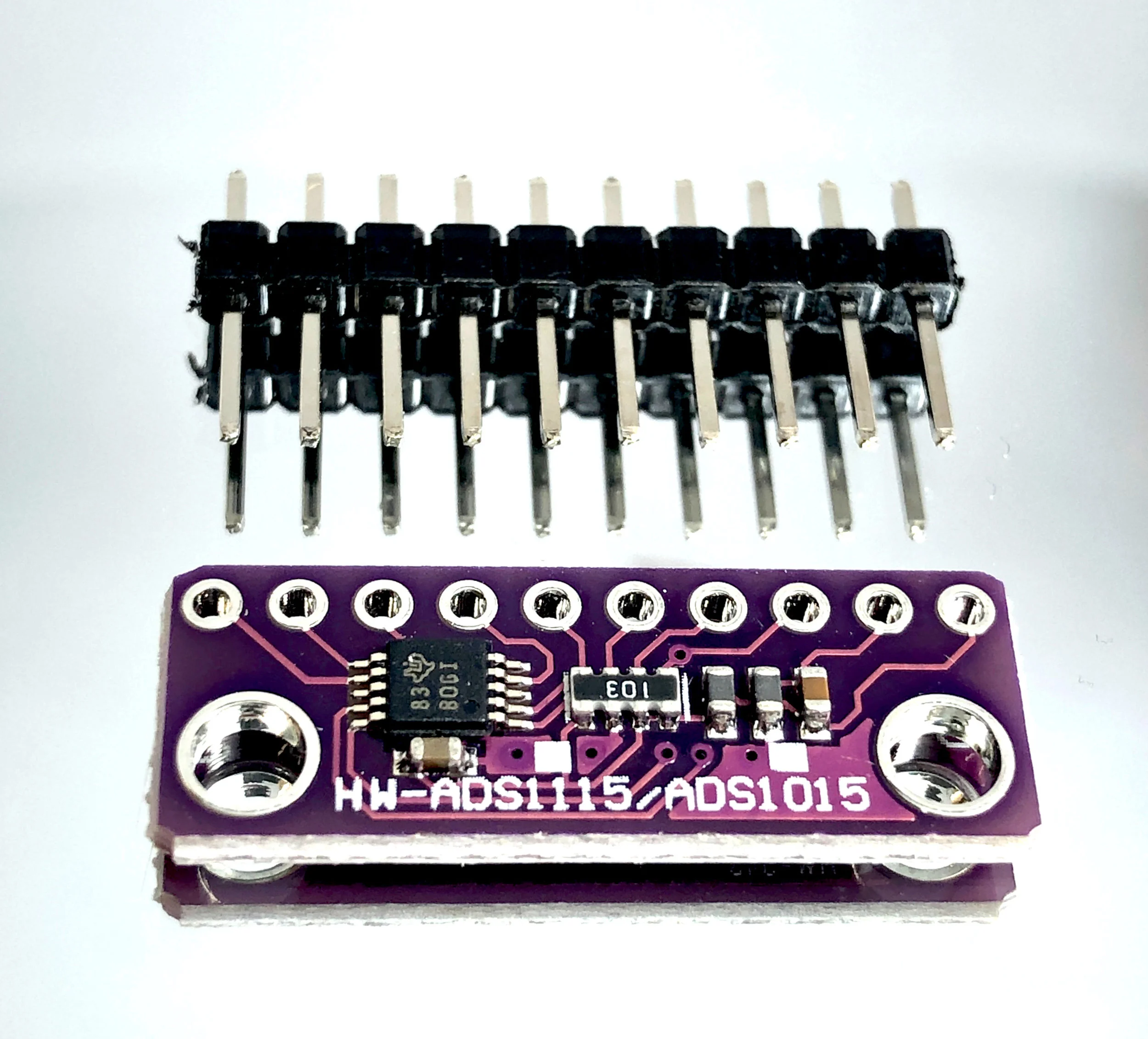
The ADS1115 is a 16-bit ADC that is a great improvement on the Arduino’s ADC resolution or incorporating an ADC into the Raspberry Pi. The ADS1115 is best for lower sample rate data acquisition (f < 1000 samples/sec).
ADS1115 Module Specifications:
4 analog channel input
Gain up to 16x
8sps - 860 sps sample rate selection
I2C communication
Raspberry Pi and Arduino Compatible
Supply Voltage 2-5V
Small Profile
Read more about the ADS1115 on Texas Instrument’s Datasheet
The component box here can fit an Arduino Uno board and several smaller sensors and jumper wires. It’s great for transporting a project from point A to point B while fitting in a pants pocket. The component box has a magnetic clasp that keeps the components secure inside. The box is also transparent, making it easy to distinguish one kit from another. The box is made from ABS plastic, which makes it sturdy and useful for preventing components from getting damaged in transit or storage.
Included in the Electronics Component Box Package:
1x Electronics Component Box
Features of the Electronics Component Box:
Dimensions: 100mm x 70mm x 21mm
Made from Strong ABS Plastic
Magnetic Clasp Closure
Fits an Arduino Uno Board and Several Sensors
3.7V LiPo batteries are useful for low-power Arduino IoT applications. The 600mAh battery shown here can power a standard Arduino Uno board for a few days under moderate processing conditions, and up to several months with the right sleep routines and modifications (power down, no LED, etc.)!
Included in the LiPo Battery Kit for Arduino:
1x 600mAh LiPo Battery
1x USB Charger
1x JST to DuPont Connector (For Wiring to Arduino)
Features of the 3.7V LiPo Battery Kit for Arduino:
600mAh LiPo Battery with USB Charger
3.7V Battery Voltage
JST connector for direct wiring to Arduino

This breadboard is great for larger projects that require a bigger wiring area. The larger breadboard has two sets of 30 x 5 ties, and two sets of positive and negative ties - each of which have 25 ties.
Included in the Large Breadboard Package:
1x Large 400 tie Breadboard

The RGB LED module allows for individual control of red, green, or blue colors all in a single module.
Included in RGB LED Module package:
1x RGB LED module
Features of RGB LED:
3.3V and 5.0V compatible
Individually addressable red, blue, and green LEDs
Arduino compatible
slim profile (4.6mm x 4.6mm RGB chip, 15mm x 24mm module dimensions)
NOTE: Our batch of these modules have reversed labels for green and red, meaning, the label R is for green, and G is for red. This was noticed after receiving and testing the modules from our manufacturer.
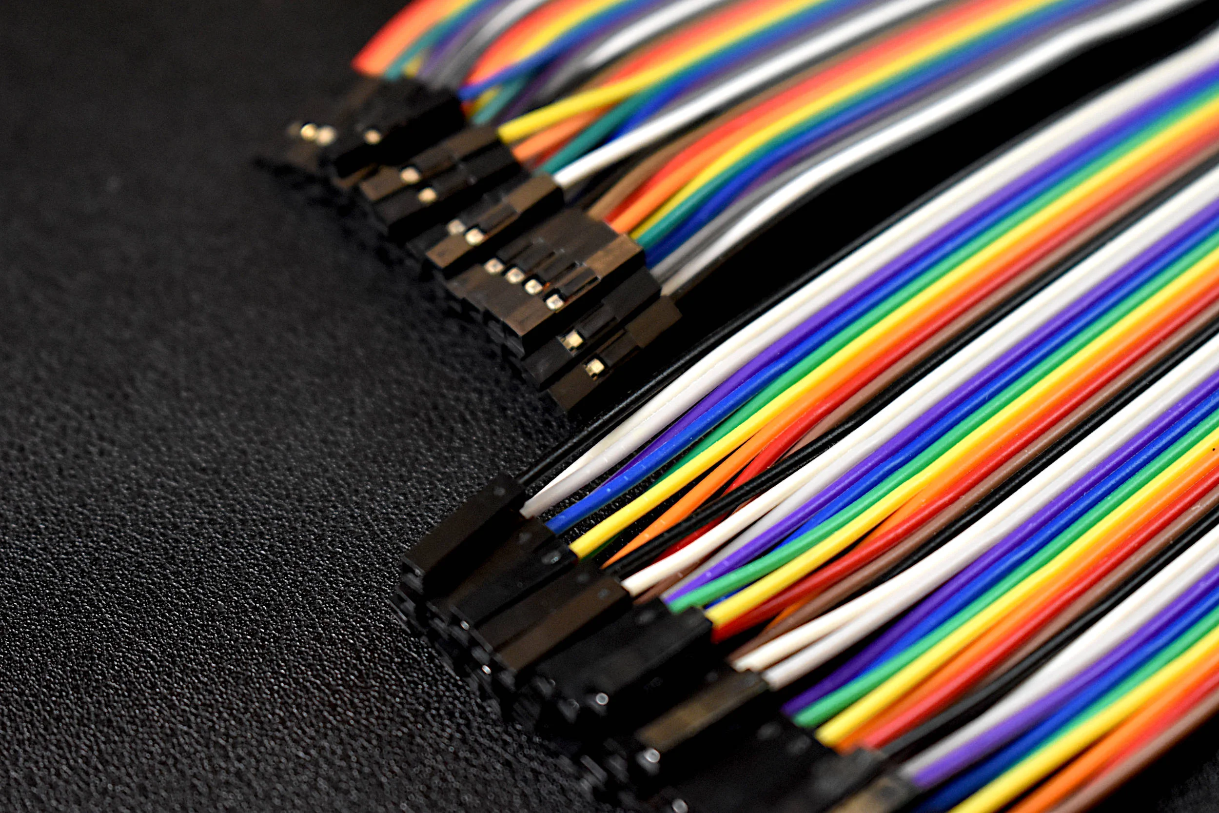
Included in Package:
Individual Jumper Wire
Often, the jumper wires are sold in packs of 120, with 40 of each male-to-male, male-to-female, and female-to-female. We decided to keep the maker’s toolbox to a minimum and allow purchase of individual jumper wires. That way, each user can choose how many jumper wires they need, what type of jumper ends they need, and just purchase that amount, ultimately minimizing the clutter on their desk or workspace.

Included:
1x Mini Breadboard
Breadboard Specs:
2 divisions of 5x17 holes (85 ties)
Great for smaller projects with Arduino Micro, NodeMCU, Particle, Arduino Xiao, sensors and more!
The SSD1306 display is an organic light emitting diode (OLED) device that is great for small-scale Arduino, Raspberry Pi, and Raspberry Pi Pico projects that involve real-time data acquisition, communication, and debugging. The display allows users to visualize and print out information related to sensors and modules — specifically when creating internet of things (IoT) nodes with microcontrollers and wireless/headless technologies. The OLED display is a versatile and has a low profile that requires just two wires for communication (I2C), which makes it easy to integrate and control.
Included in the SSD1306 OLED Display Package:
1x SSD1306 OLED Display
Features of the SSD1306 OLED Display:
3V-5V Supply Range
2mA - 24mA Consumption Range (Blank to All Pixels Bright)
128 x 64 Pixel HD Resolution
I2C 2-Wire Protocol (I2C address: 0x3C)
White Display Colors Against Dark Backdrop
Compatible with Arduino, Raspberry Pi, and Raspberry Pi Pico
Module Dimensions: 25mm x 27mm
Active Display Dimensions: ~ 21mm x 12.5mm (0.96” Diagonal)
Arduino Tutorial with SSD1306 here
Electronic paper, known as e-Paper, is a common technology used in devices such as the Amazon Kindle and Nook eReaders and eBooks. The e-Paper module here uses SPI to communicate with Arduino boards and display text at very low power consumption. e-Paper is highly advantageous for displays that update very infrequently, as they can retain the last printed image on their screen even in the absence of power. The e-Paper module here can be powered via 3.3V or 5.0V, and is compatible with Arduino boards.
Included in the e-Paper Display for Arduino Package:
1x 1.54 inch e-Paper Display Module (200x200 Pixels)
1x JST XH 2.54mm to Dupont 8-Pin Connector
Features of the 1.54in e-Paper Display Module:
Module Dimensions: 40mm x 55mm
Active Area Dimensions: 1.09 in. x 1.09 in. [1.54 in. Diagonal]
1.8V-5.3V Supply Voltage
Power Consumption Profiles @ 3.3V:
3mA Idle Current
2mA - 7mA Update Current
Resolution: 200 x 200 Pixels (~185 dpi)
Full/Partial Refresh Capabilities
Max Refresh Rate ~2 seconds (Partial), ~5 seconds (Full)
SPI Interface (Compatible with Arduino and Raspberry Pi)
See our tutorial interfacing the e-Paper display and Arduino!
The RGB LED ring light uses an array of 16 surface mounted light-emitting diodes that are programmable by Raspberry Pi computers, Arduino boards, and Raspberry Pi Pico microcontrollers. The RGB LEDs used in the 16-pixel ring light are similar to the common WS2812B LEDs. Each LED is individually addressable, which allows users to control all 16 LEDs. Each RGB LED can be altered using 24-bit configuration commands, which results in 16,777,216 possible colors for each LED.
Included in the 16-Pixel RGB LED Ring Light:
1x 16-Pixel RGB LED Ring
1x 3D-Printed Enclosure (Translucent Dome, Black Backing Plate)
Features of the 16-Pixel RGB LED Ring Light:
16 RGB LEDs Soldered to PCB Ring
5V Supply Voltage
0.55A Max Current Consumption (35mA per LED)
Dimensions:
PCB: 72mm Radius, 3mm Thickness
Enclosure: 78mm x 88mm x 10mm
All 16 LEDs are Individually Addressable
16,777,216 Possible Colors Per LED
Only 3-Wires Required for Control and Power
3D-Printed Enclosure Allows for Holding and Attaching (M3 Screw)
Compatible with Arduino, Raspberry Pi, Raspberry Pi Pico
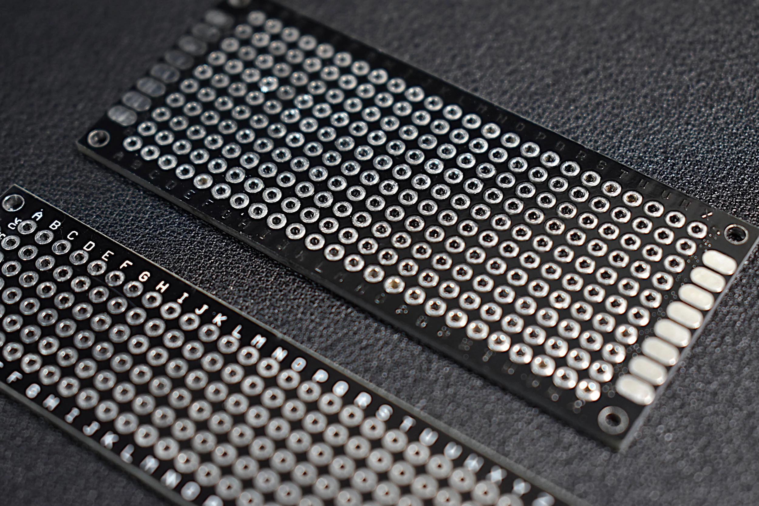
Printed circuit boards (PCBs) are great for projects nearing the finish line and preparing for market. These black, double-sided PCBs are small enough to fit into an internet of things (IoT) box, but also large enough to allow multiple components to be soldered along the width of the PCB.
Included in the Double-Sided PCB Package:
1x Double-Sided Black PCB
Some features of the printed circuit boards:
20mm x 80mm (6x28 holes) or 30mm x 70mm (10x24 holes)
Black and sleek design
Double-sided plating allows for easy soldering
Mounting holes at the corners
Lettering for easy designation of solder points
These vibration motors are great for testing haptic feedback with Arduino and Raspberry Pi. The voltage, ground, and PWM pinouts make it easy to get started with vibration feedback. This module starts vibrating at 3.7V, thus it should be used with a 5V system.
Included with the Vibration Motor:
1x Vibration Motor Module for Arduino
Features of the Vibration Motor:
5V Voltage Rating
60mA - 90mA Power Consumption
Dimensions:
10mm (Radius of Vibration Motor)
21mm x 23mm (PCB)
21mm x 28mm (PCB w/Pins)
PWM Controlled
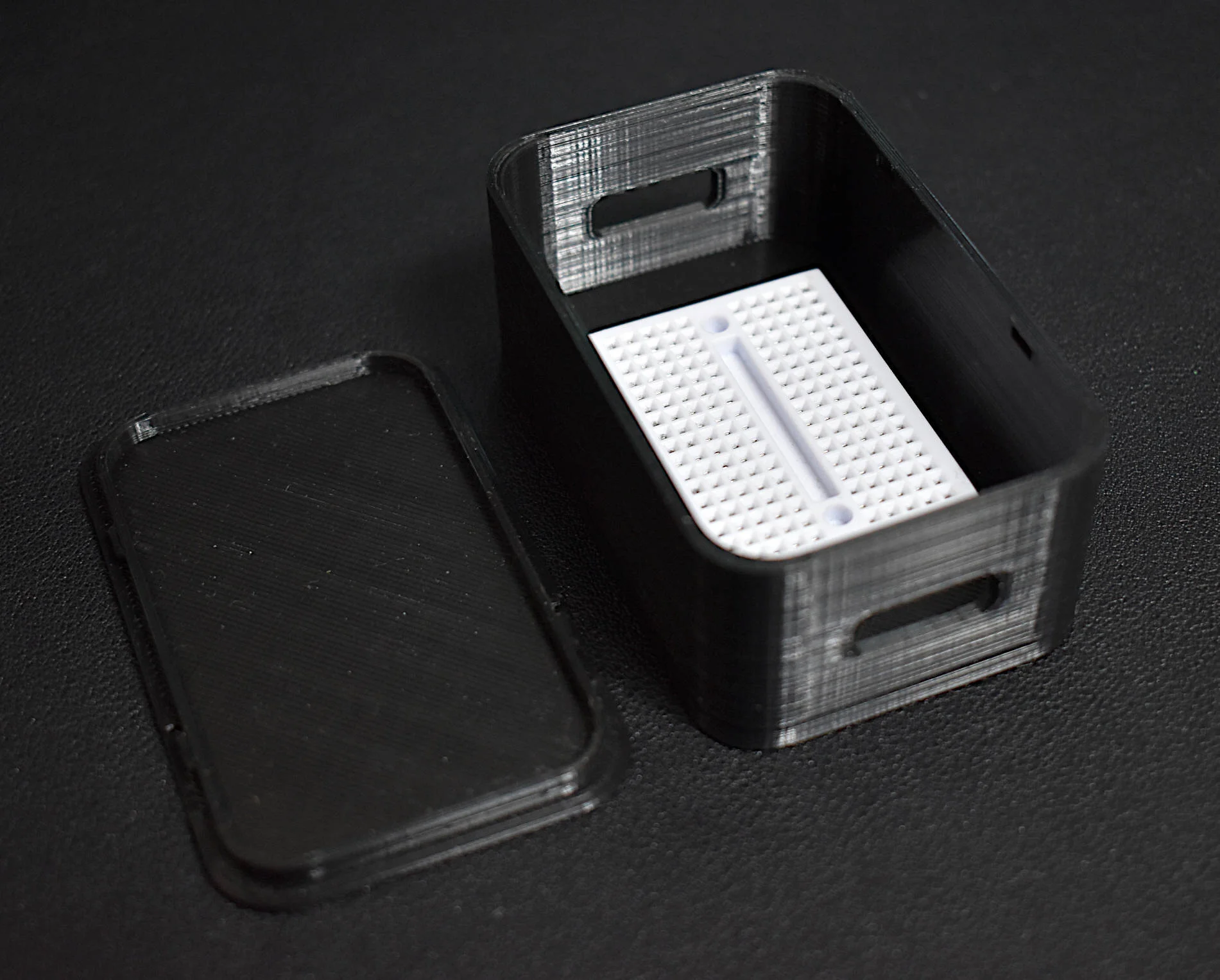
An enclosure can be an important asset when prototyping with Arduino boards and sensors. The mini breadboard enclosure is useful for smaller projects, where the user can cover the wiring and pinouts from sensors and microcontrollers. The enclosure has a removable lid that makes it easy to alter wiring and components, while also being lightweight and sleek. We use the mini breadboard enclosure for Arduino Xiao projects, Arduino Pro Micro projects, and testing and assembling sensor kits.
Included in the Mini Breadboard Enclosure:
1x Mini Breadboard
1x Enclosure and Lid
Features of the Mini Breadboard Enclosure:
Outside Dimensions: 80mm x 50mm x 33mm
Inside Dimensions: 76mm x 46mm x 27mm
Mini Breadboard Sits In Place
Removable Lid to a Snap
Holes for USB Ports and External Wiring
Black Color
The MLX90640 is a 768-pixel (32 x 24), low-cost thermal camera. It uses an array of infrared detectors (and filters) to detect the radiation given off by nearby objects by taking advantage of Planck’s radiation law. The MLX90640 is most notable because of its easy-to-use Python libraries that allow it to be read by Raspberry Pi computers. The MLX90640 can be used to map and record high-resolution temperature maps at refresh rates of up to 64 times per second (64Hz).
NOTE: There are two versions here, 1. an unsoldered board that needs to be soldered to be wired properly; and 2. a version that has a breakout connector that can be connected directly to a Raspberry Pi via the JST Dupont connector.
Included in the MLX90640 Thermal Camera Sensor Package:
1x MLX90640 Thermal Camera (32 x 24 Pixels, 55° x 35°)
Pin Header
5x Male-to-Female Jumper Wires (or JST Dupont connector for breakout version)
Features of the MLX90640 Thermal Camera:
Object Detection Temperatures: -40°C to +300°C
3V-6V Supply Voltage
20mA Average Current Consumption
32 x 24 Resolution, 768 Pixels in Total
55° x 35° Field of View
I²C Communication (Address: 0x33)
Ambient Temperature Operating Range: -40°C to +85°C
Raspberry Pi and Arduino Compatible
JST Dupont Breakout Pinouts:
Black for GND
Red for V+
Blue for SDA
Yellow for SCL
MLX90640 Datasheet
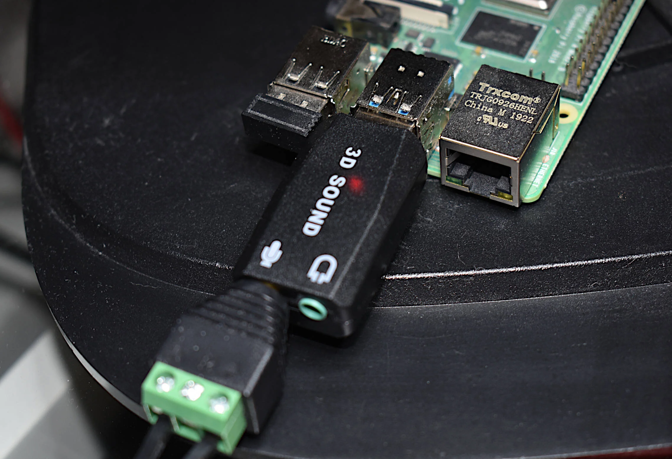
The USB datalogger is a simple way to acquire high frequency data from the USB port of the Raspberry Pi computer. The USB sound card shown here, allows sample rates up to 48kHz. The USB datalogger is great for high frequency audio recording or high frequency vibration recording, particularly in the analog domain.
Included in the Raspberry Pi USB Datalogger Kit:
1x USB Datalogger
1x 3.5mm Terminal Breakout
Some Features of the USB Datalogger:
44.1kHz/48kHz Sample Rates
Single Channel Input
5V Maximum Input
Compatible with Analog Devices
High Frequency Datalogging
Terminal Breakout makes it easy to prototype
The QuadMic Array is a 4-microphone array based around the AC108 quad-channel analog-to-digital converter (ADC) with Inter-IC Sound (I2S) audio output capable of interfacing with the Raspberry Pi. The QuadMic can be used for applications in voice detection and recognition, acoustic localization, noise control, and other applications in audio and acoustic analysis. The QuadMic can be connected to the header of a Raspberry Pi computer and used to record simultaneous audio data from all four of its microphones. Some applications of the QuadMic are: characterizing noise sources, room and spatial geometries, and other aspects of acoustic systems.
Included in the QuadMic 4-Microphone Array Package:
1x QuadMic 4-Microphone Array
Features of the QuadMic 4-Microphone Array:
Four SPU0414HR5H MEMS Microphones
100Hz - 10kHZ Flat (4dB) Frequency Response
16kHz Sample Rate for Each Microphone
I2S Audio Protocol
I2C Output Connector
GPIO 12/13 Available via Output Connector
12 Addressable RGB LEDs via SPI
Compatible with Raspberry Pi
Electronic Wiring Diagram can be found here
Read about the AC108 Analog-to-Digital Converter here
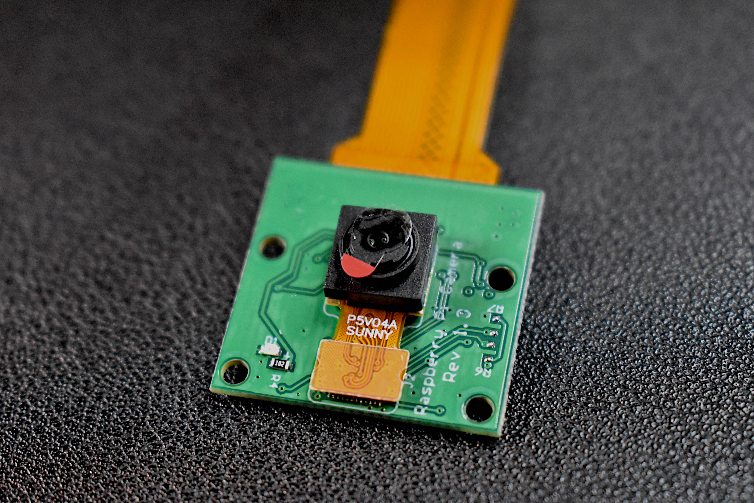
Included in the Package:
1x Raspberry Pi 5MP Camera
1x Ribbon Cable
NOTE: If a Raspberry Pi Zero is being used, select the RPi Zero from the dropdown menu below. If a longer cable is desired, select the standard cable with a longer length (only available for RPi 2,3,4; not Zero).
The Raspberry Pi camera is 5 megapixels in resolution and is fully compatible with Raspberry Pi 2B, 3, 3B, 3B+, and 4. It also works with the Zero and Zero W (with the correct ribbon cable). The picamera has a dedicated Python library that allows users to control the camera and take photos and record video. The library also allows users to control the white balance, shutter, and read each RGB pixel directly from the camera.
Some Features of the Picamera:
5MP Max photograph resolution (2592 x 1944 = 5,038,848 pixels)
Ribbon Cable that attaches directly to the Raspberry Pi
Pixel Size: 1.4 x 1.4 μm
Lens: f=3.6 mm, f/2.9
Viewing Angle: 54° x 41°
Max video resolution: 1080p @ 30fps
Max frame rate: 480p @ 90fps
Selectable video resolutions: 1080p @ 30fps, 720p @ 60fps, 480p @ 90fps
Sensor size: 3.67mm x 2.74mm (1/4" format)
Camera Module PCB dimensions: 25mm x 24mm (9mm thickness)
Documents on Python’s picamera library can be found here.

The Raspberry Pi 4 Computer, Model B is the latest in the series of single-board computers (SBC) produced by the Raspberry Pi Foundation. The RPi 4 increased its processor speed, its GPU performance, memory (1GB, 2GB, 4B, 8GB options), and connectivity. The Raspberry Pi 4 computer continues to be an essential tool in the maker, programmer, and engineer communities. The Raspberry Pi 4 is capable of interfacing with a wide range of sensors, motors, actuators, and devices. The RPi 4 has the standard 40-pin header with general purpose input/outputs (GPIOs), Bluetooth and WiFi capabilities, HDMI output display abilities, and much more! Our site contains a variety of different tutorials in the categories of Python programming, data acquisition and analysis, motor control, internet of things (IoT), engineering, among others.
Included with the Raspberry Pi 4 Model B Computer:
1x Raspberry Pi 4 Model B Computer
Features of the Raspberry Pi 4 Model B Computer:
Broadcom BCM2711, Quad core Cortex-A72 (ARM v8) 64-bit SoC @ 1.5GHz
LPDDR4-3200 SDRAM (2GB, 4GB, 8GB depending on the model)
2.4 GHz and 5.0 GHz WiFi, Bluetooth 5.0, Bluetooth Low Energy (BLE)
Gigabit Ethernet
2x USB 3.0 ports; 2x USB 2.0 ports
Raspberry Pi standard 40-pin GPIO header (fully backwards compatible with previous boards)
2x micro-HDMI ports (up to 4K @60fps supported)
2-lane MIPI DSI display port, 2-lane MIPI CSI camera port
4-pole stereo audio and composite video port
H.265 (4kp60 decode), H264 (1080p60 decode, 1080p30 encode)
Micro-SD card slot for loading operating system and data storage
5V DC via USB-C connector, 5V DC via GPIO header (3A Recommended Supply)
Operating Temperature (Ambient): 0°C – 50°C
Raspberry Pi Peripherals:
6x UART, 6x I2C, 5x SPI, 1x SDIO, 1x DPI, 1x PCM, 2x PWM Channels, 3x GPCLK
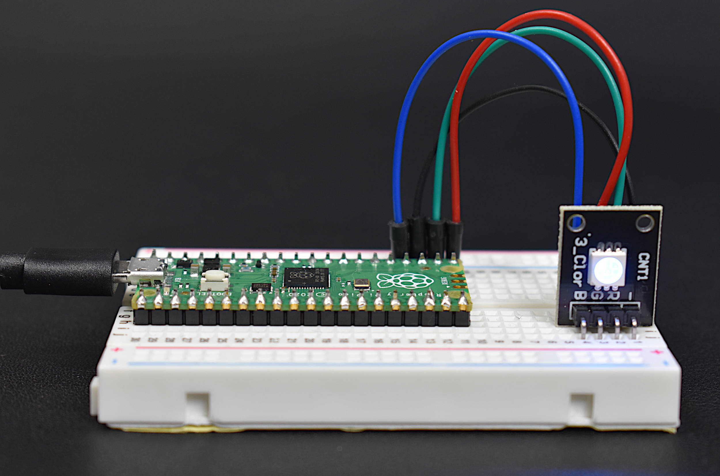
The Raspberry Pi Pico is a new microcontroller designed by the Raspberry Pi foundation. The Pico is a groundbreaking board that is meant to use MicroPython in its native micro USB port. The RP2040 is the microcontroller chip at the center of the Pico, which has a dual-core Arm Cortex M0+ processor, capable of clocking at 133 MHz, which is much faster than many of the Arduino boards currently on the market. The Pico has GPIO pins and interfaces such as: SPI, UART, I2C, PWM, and a 12-bit analog-to-digital converter (ADC). This Raspberry Pi Pico Kit comes with the Pico microcontroller, an RGB LED, a breadboard, jumper wires, and USB cable.
Included in the Raspberry Pi Pico Starter Kit:
1x Raspberry Pi Pico Board
2x 20-pin Headers
1x Black 0.5m Micro USB Cable
1x RGB LED
4x Male-to-Male Jumpers
1x Half Breadboard (White)
Features of the Raspberry Pi Pico:
1.8V - 5.5V Input Voltage
21 mm × 51 mm Board Geometry
RP2040 microcontroller
Dual-core Arm Cortex-M0+ processor (Clock Speed up to 133 MHz)
264KB on-chip SRAM, 2MB on-board QSPI Flash
26x GPIO pins (3x 12-bit Analog Inputs)
2x UART, 2x SPI, 2x I2C, 16x PWM
1x USB 1.1 controller and PHY, with host and device support
8x Programmable I/O (PIO) state machines for custom peripheral support
Operating temperature -20°C to +85°C
Low-power sleep and dormant modes
Onboard Temperature sensor
Accelerated integer and floating-point libraries on-chip
NOTE: Our batch of RGB LED modules have reversed labels for green and red, meaning, the label R is for green, and G is for red. This was noticed after receiving and testing the modules from our manufacturer.

This is the DHT22 temperature sensor bundle that will provide temperature and humidity data to an Arduino which will be recorded by an iOS device via the BLExAR app. BLExAR allows users to visualize and save data in real-time.
Included in the BLExAR DHT22 Temperature Sensor Bundle:
1x Arduino Uno (w/USB Cable)
1x CC2541 Bluetooth Module
1x DHT22 Temperature Sensor
1x Mini breadboard (Colors may vary)
10x Jumper Wires
Features of the DHT22 Temperature Sensor:
3.3-6V Supply Voltage
DHT22 Operating Ranges:
Relative Humidity: 0-100 %
Temperature -40 °C to 80 °C
Sample Rate ~ 2 seconds
Sensitivity:
Relative Humidity: ± 0.1 %
Temperature: ± 0.1 °C
Accuracy (Drift and calibration errors):
Relative Humidity: ± 2-5 %
Temperature: ±0.5 °C
Specifications for Arduino Uno Rev3 Board:
ATmega328P chip with Arduino Bootloader
14 digital pins, 6 analog pins
10-bit analog-to-digital converter (ADC)
5V-12V Supply Tolerance
3.3V and 5.0V output pins
16 MHz clock
5 PWM pins, I2C support, SPI support , UART support
ATmega16U2 USB TTL, compatible with Linux, Windows, and Mac
Black Stylish Finish
Fully Integrated with Arduino IDE software
Features of the CC254x Bluetooth Module:
Active-Mode RX Down to: 17.9 mA
Active-Mode TX (0 dBm): 18.2 mA
Power Down Sleep Mode: 60uA
Wide Supply-Voltage Range (3.6 V - 5V)
Serial Communication

The BLExAR Board with CC2541 Bluetooth Module is meant to interface with the BLExAR App for iOS. The BLExAR board can be controlled using the BLExAR app and an iOS device. The BLExAR board can also be programmed to communicate with an iOS device (iPhone or iPad).
The BLExAR Arduino Uno kit can be used to collect data, control robots, talk to your iOS device, and much more!
Included in the kit:
1x Arduino Uno Board
1x USB Cable
1x CC2541 Bluetooth Module
6x Male-to-Female Jumper wires

This bundle includes the necessary components to follow along with the RGB LED fade tutorial using the BLExAR app. The user will wire, program, and demonstrate how to change the color of a tri-color LED with the BLExAR app using both PWM control and on-off switches on the app. The PWM control of the RGB LED lets users select from a range of colors using a combination brightness of the three colors available on the LED.
This kit comes with the following components:
1x Maker Portal Arduino Uno Board
1x Black USB 2.0 Cable (1m)
1x CC2541 Bluetooth Module
1x RGB LED (with 3 anode legs, 1 cathode leg)
1x Mini Breadboard
8x Male-to-Male Jumper Wires
*iOS device NOT included!
NOTE: Our batch of RGB LED modules have reversed labels for green and red, meaning, the label R is for green, and G is for red. This was noticed after receiving and testing the modules from our manufacturer.
The TinyBlueX is a combination module that contains an ATtiny85 microcontroller and CC254x Bluetooth Low Energy chip that is compatible with Arduino and the BLExAR iOS app. The TinyBlueX is very low power and low profile, which makes it great for simple internet of things (IoT) applications. The TinyBlueX can read sensors and transmit the data back to an iOS device. The TinyBlueX can also be controlled using the BLExAR app to turn LEDs, motors, and actuators on and off using the ATtiny’s GPIO pins. Pins 2,3,7 are available on the module, allowing the user to control/read up to three different devices or sensors.
Included with the TinyBlueX Module:
1x TinyBlueX Module
1x ATtiny85 Microcontroller
1x CC254x Bluetooth Low Energy Module
8x Female-to-Male Jumper Wires
Features of the TinyBlueX Module:
Dimensions: 56mm x 35mm x 18mm (Assembled)
Arduino IDE Compatible (Arduino as ISP Required)
Removable ATtiny85 Microcontroller and BLE Module
3.6V - 5.5V Supply Voltage Range
Bluetooth Low Energy Communication
Compatible with BLExAR iOS App
3x Analog Input Pins (10-bit) [Pins 2,3,7]
3x General Purpose Input/Output (GPIO) Pins [Pins 2,3,7]
1x External Interrupt Pin [Pin 7]
0MHz - 10MHz @ 3.6V-5.5V, 0MHz - 20MHz @ 4.5V - 5.5V
Low Power Modes with Watchdog Timer
This Arduino Nano board is paired with a Bluetooth Low Energy (BLE) chip that makes it both an Arduino board and a BLE-enabled device. The BLE-Nano has all the functionality of an ATmega328P microcontroller (Arduino Nano) while also having an integrated BLE chip wired to its serial pins. This means that many of your Arduino projects can be Bluetooth-enabled with just a few lines of code and the BLExAR app!
NOTE: Due to supply chain issues, the BLE-Nano has been discontinued from our store. Please see the MakerBLE Arduino Board as an improvement and alternate.
Included in the BLE-Nano Package:
1x Soldered BLE Nano Board (ATmega328P + CC2540)
1x Black Micro USB Cable
Some Features of the BLE-Nano Arduino Board:
ATmega328P Microcontroller
Arduino Nano Bootloader
Operating Voltage: 5V (Input: 5V - 12V)
16 MHz Clock Speed
Available I/O Pins: 12 Digital, 8 Analog
6 Digital PWM Pins
Current Usage: 19 mA
Profile: 48 x 19mm
Weight: 7 g
Arduino IDE Compatible
CC2540 Bluetooth Low Energy Chip
Serial Communication with Nano (pins 0/1)
2.4 GHz Bluetooth Communication
Compatible with BLExAR iOS App
Onboard Antenna
The MakerBLE board is a Bluetooth Low Energy (BLE) microcontroller development board based on Nordic’s nRF52840 chip. The MakerBLE acts as an Arduino board and a BLE-enabled device. It has much of the functionality of classic Arduino boards, while also having an integrated BLE chip capable of communicating via BLE 5.0. This means that many Arduino projects can be Bluetooth-enabled with just a few lines of code and the BLExAR app!
→ Getting Started Tutorial for MakerBLE Board ←
Included in the MakerBLE Package:
1x MakerBLE Board
2x 7-Pin Header
1x Black USB-C to USB2.0 Cable (1m long)
Some Features of the MakerBLE Board:
Arduino Bootloader
Nordic nRF52840, ARM® Cortex™-M4 32-bit processor with FPU operating at 64 MHz
3.3V Operating Voltage and Logic
3.3V-5V Input voltage (3.7V LiPo Battery Compatible)
Ultra-low sleep power: 5 μA, deep sleep model
Wireless capabilities: Bluetooth 5.0, NFC, and ZigBee module with onboard antenna
Multiple Peripherals: 1x Reset button, Ix UART, 1x IIC, 1x SPI, 1x NFC, 1x SWD, 11x GPIO, 6x ADC, 1x Three-in-one LED,1x User LED
Onboard 2 MB flash
Single-sided components, surface mounting design (low profile)
14 Available I/O Pins: 11 Digital, 6 Analog
Physical Dimensions: 21mm x 17.5mm
Weight: 3 g (Unsoldered), 5g (Soldered)
Arduino IDE Compatible
GitHub Repository with example scripts and projects

Water Wise Controls (WaWiCo) is a California-based company focused on water metering solutions using the acoustic profile of piping systems. Using this USB water metering kit, users can listen to their pipes and determine, based on advanced acoustic signal processing algorithms, whether water is flowing through a complex piping system. The USB metering kit includes a USB adapter for any PC and a flexible MEMS microphone band that can be attached to pipes ranging from 1”-2” in diameter.
Included in the USB Water Metering Kit:
1x Flexible Band with MEMS Microphone
1x 2-m Connector Cable
1x Wired USB Adapter
Features of the USB Water Metering Kit:
USB Sample Rate: 44.1kHz or 48kHz
16-bit Data Acquisition Precision
MEMS Microphone Frequency Response: 100Hz - 15kHz
Flexible Band for 1”-2” Diameter Piping
Compatible with Mac, Windows, and Linux-based Systems (Including Raspberry Pi)

Water Wise Controls (WaWiCo) is a California-based company focused on water metering solutions using the acoustic profile of piping systems. Using this USB water metering kit, users can listen to their pipes and determine, based on advanced acoustic signal processing algorithms, whether water is flowing through a complex piping system. The USB metering kit includes a USB adapter for any PC and a flexible MEMS microphone band that can be attached to pipes ranging from 1”-2” in diameter.
Included in the USB Water Metering Kit:
1x MEMS Microphone
1x 6-ft 20AWG Connector Wire
1x USB Sound Card
3x 3D Printed Parts: USB Housing Case, Flexible USB Housing, Flexible MEMS Pipe Band
5V to 3.3V Voltage Regulator
Heat Shrink Tubing
2x JST Connector (1x Male, 1x Female)
Zip Tie for Flexband Securing
Features of the USB Water Metering Kit:
USB Sample Rate: 44.1kHz or 48kHz
16-bit Data Acquisition Precision
MEMS Microphone Frequency Response: 100Hz - 15kHz
Flexible Band for 1”-2” Diameter Piping
Compatible with Mac, Windows, and Linux-based Systems (Including Raspberry Pi)
The Raspberry Pi Pico is a microcontroller designed by the Raspberry Pi foundation. The Pico is a groundbreaking board that is meant to use MicroPython in its native micro USB port. The RP2040 is the microcontroller chip at the center of the Pico, which has a dual-core Arm Cortex M0+ processor, capable of clocking at 133 MHz, which is much faster than many of the Arduino boards currently on the market. The Pico has GPIO pins and interfaces such as: SPI, UART, I2C, PWM, and a 12-bit analog-to-digital converter (ADC). This Raspberry Pi Pico comes with the Pico microcontroller, 2x 20-pin solder header, and a micro-USB cable.
Included with the Raspberry Pi Pico Microcontroller:
1x Raspberry Pi Pico Board
2x 20-pin Headers
1x Black 0.5m Micro USB Cable
Features of the Raspberry Pi Pico:
1.8V - 5.5V Input Voltage
21 mm × 51 mm Board Geometry
RP2040 microcontroller
Dual-core Arm Cortex-M0+ processor (Clock Speed up to 133 MHz)
264KB on-chip SRAM, 2MB on-board QSPI Flash
26x GPIO pins (3x 12-bit Analog Inputs)
2x UART, 2x SPI, 2x I2C, 16x PWM
1x USB 1.1 controller and PHY, with host and device support
8x Programmable I/O (PIO) state machines for custom peripheral support
Operating temperature -20°C to +85°C
Low-power sleep and dormant modes
Onboard Temperature sensor
Accelerated integer and floating-point libraries on-chip
Raspberry Pi Pico Datasheet, RP2040 Datasheet