MPU6050 Arduino High-Frequency Accelerometer and Gyroscope Data Saver
“As an Amazon Associates Program member, clicking on links may result in Maker Portal receiving a small commission that helps support future projects.”
The MPU6050 is a 6-DoF (degree of freedom) accelerometer and gyroscope that is designed for inexpensive, small-scale, and efficient approximation of motion. Accelerometers and gyroscopes are used in smart phones for orientation detection, vibration analysis in vehicles and machines, and even camera stabilization and motion tracking. There are countless applications for accelerometers and gyroscopes, and with devices as accessible as the MPU6050, we can really test the limits of the technology.
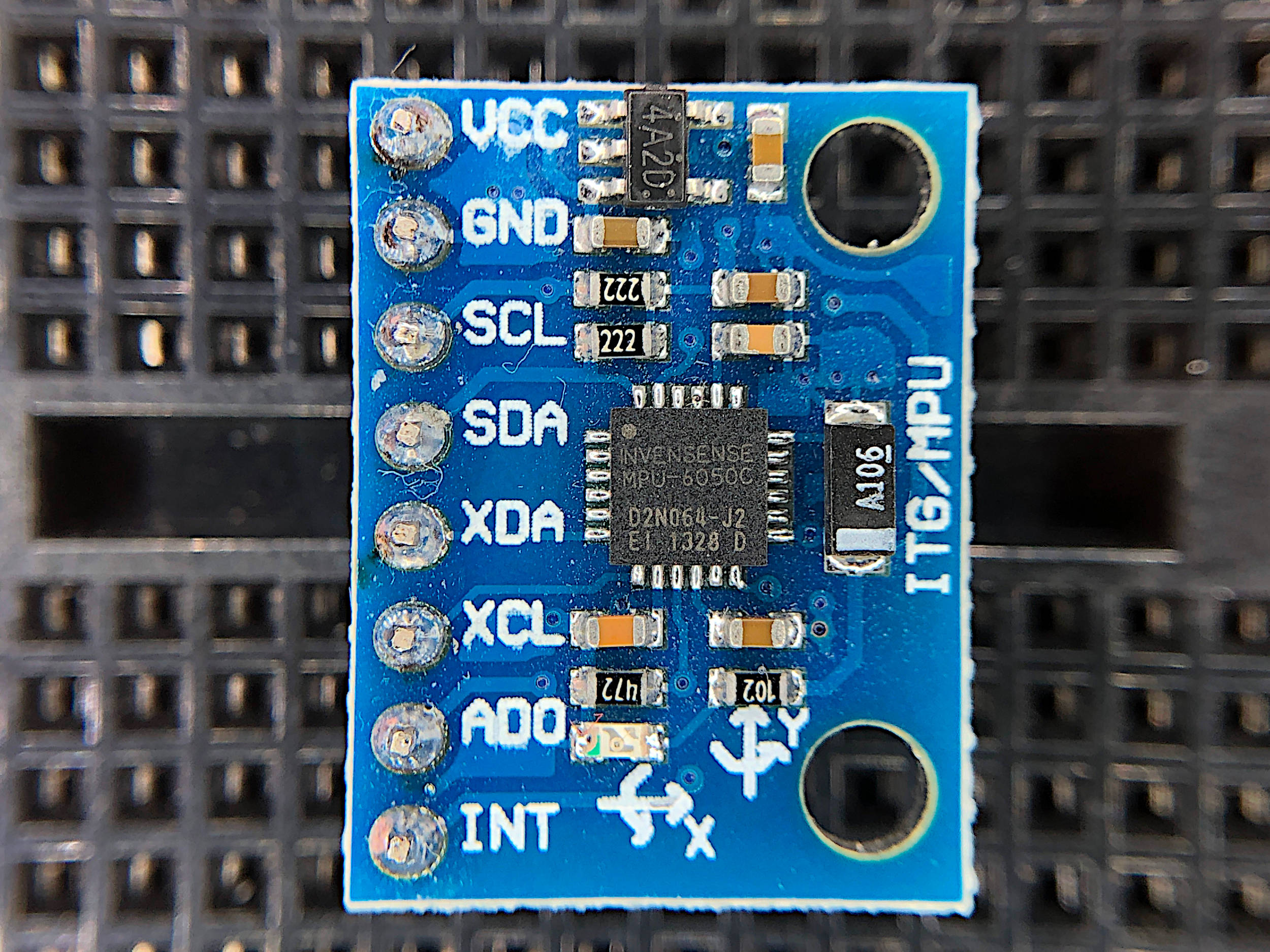
The MPU6050 features three 16-bit analog-to-digital converters (ADCs) for digitizing the gyroscope outputs and three 16-bit ADCs for digitizing the accelerometer outputs. For this specific tutorial, the gyroscope range spans ±250°/sec, and the accelerometer range spans ±2g. The MPU6050 uses the I2C serial communication, which can be interfaced using pins A4/A5 (SDA/SCL) on the Arduino Uno board. The sensor also uses 3.3V as the supply voltage. The gyroscope and accelerometer can be sampled between 1-8kHz, but the limitations of the SD module will restrict the sample rate down to 500 Hz - which suffices for many applications (full datasheet for MPU6050 here).
The Arduino Uno board will be used as the controller for acquiring data from the MPU6050 at high speeds. An SD module will also be used to save the data in real time for analysis and post processing. This will more flexibility of the analysis while also allowing for portable applications such as tracking and vibration analysis (which would be very difficult with an Arduino board). The parts needed to replicate the experiments in this tutorial are listed below:
Arduino Uno - $13.00 [Our Store]
MPU6050 Accelerometer + Gyroscope - $7.00 [Our Store]
SD Module - $8.00 [Our Store]
16 GB SD Card + USB Reader - $10.00 [Our Store]
3.7V LiPo Battery - $18.99 (4 pcs + charger) [Amazon]
3.7V to 5V Boost Converter - $7.99 (2 pcs) [Amazon]
Mini Breadboard - $3.00 [Our Store]
Jumper Wires - $5.99 (120 pcs) [Amazon]
Raspberry Pi 3B+ Kit - $48.99 [Amazon]

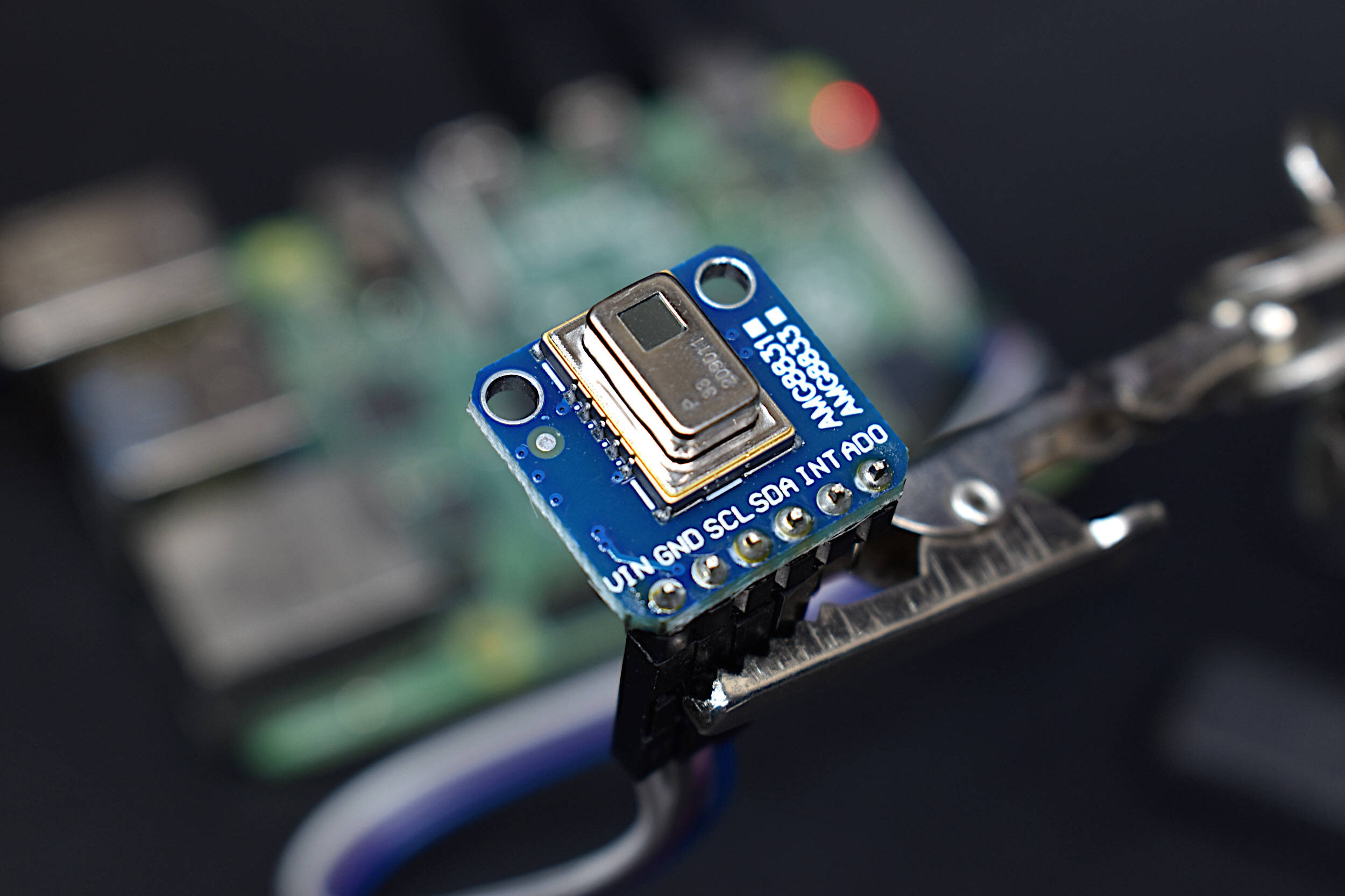
The MPU6050 is a 6-degree of freedom (DoF) inertial measurement unit (IMU) that measures acceleration in gravitational units (g) and angular velocity in degrees per second. The sensor has an onboard accelerometer and gyroscope that return 16-bit signed digital units, making the device fairly accurate for measuring rotation and accelerations in the three cardinal directions. The MPU6050 also measures temperature using an onboard temperature sensor.
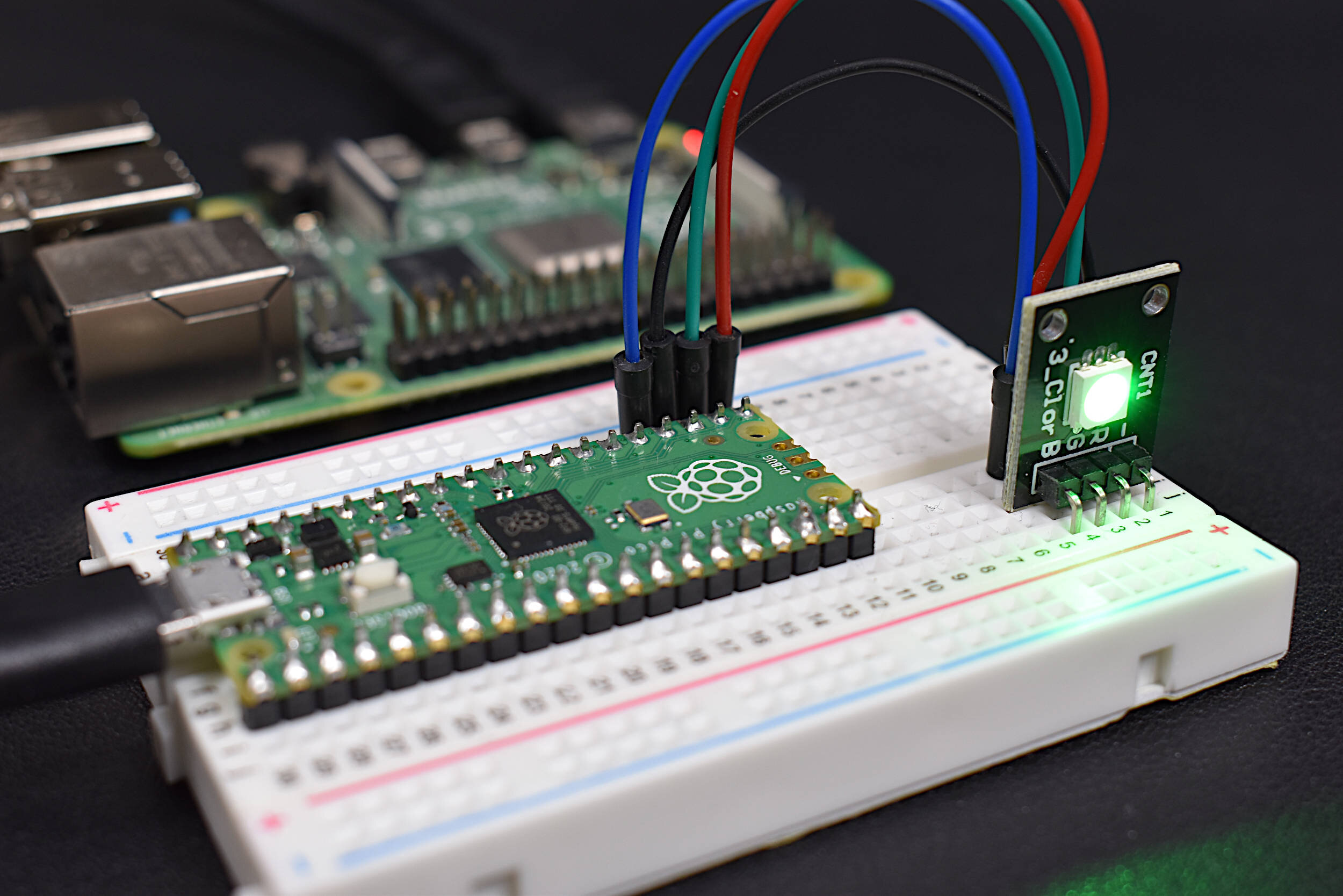
The MPU6050 is fully compatible with Arduino and Raspberry Pi
Included in the MPU6050 sensor package:
MPU6050 Sensor
8-pin header
A tutorial using the MPU6050 IMU can be found on our site at: https://makersportal.com/blog/2019/8/17/arduino-mpu6050-high-frequency-accelerometer-and-gyroscope-data-saver
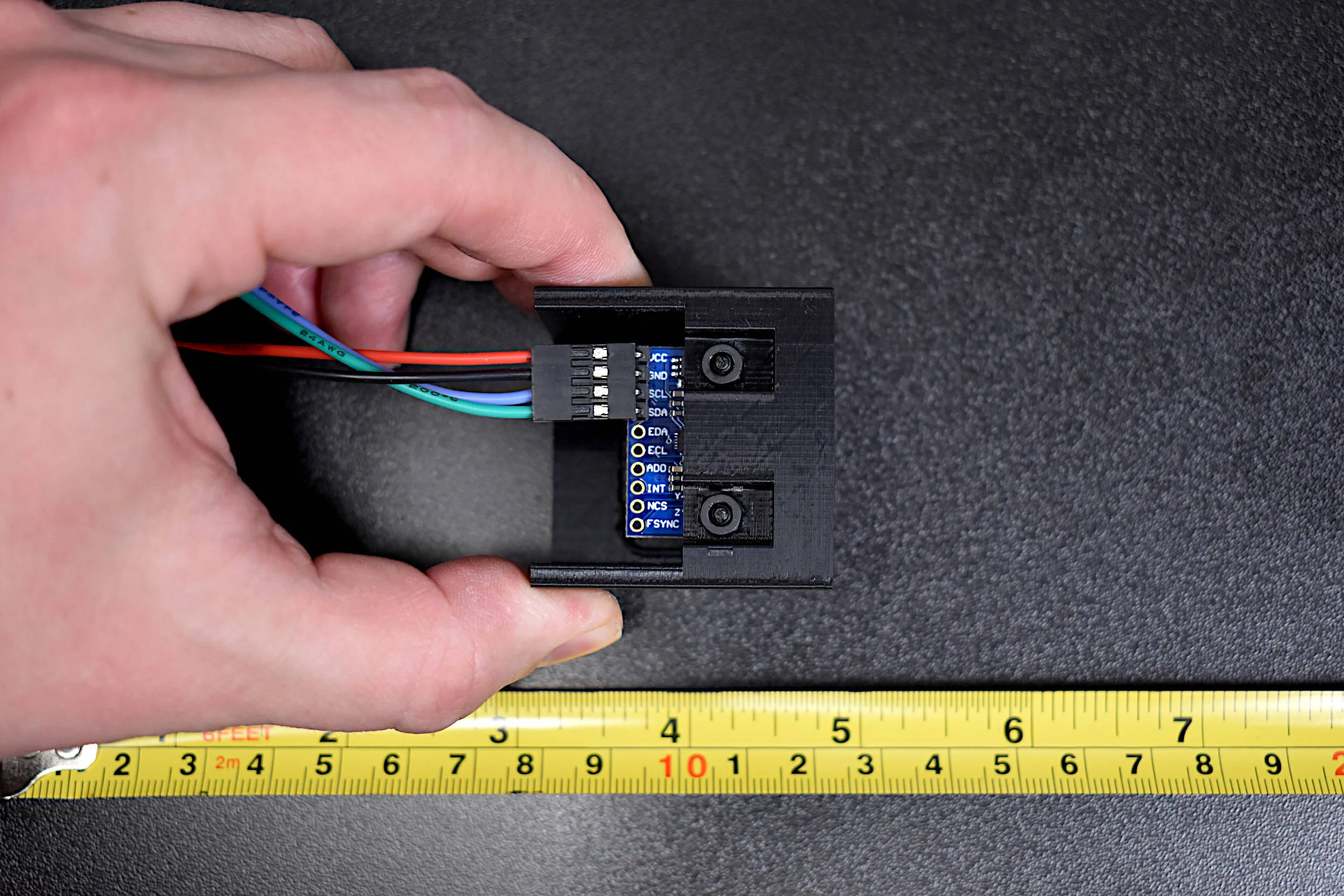
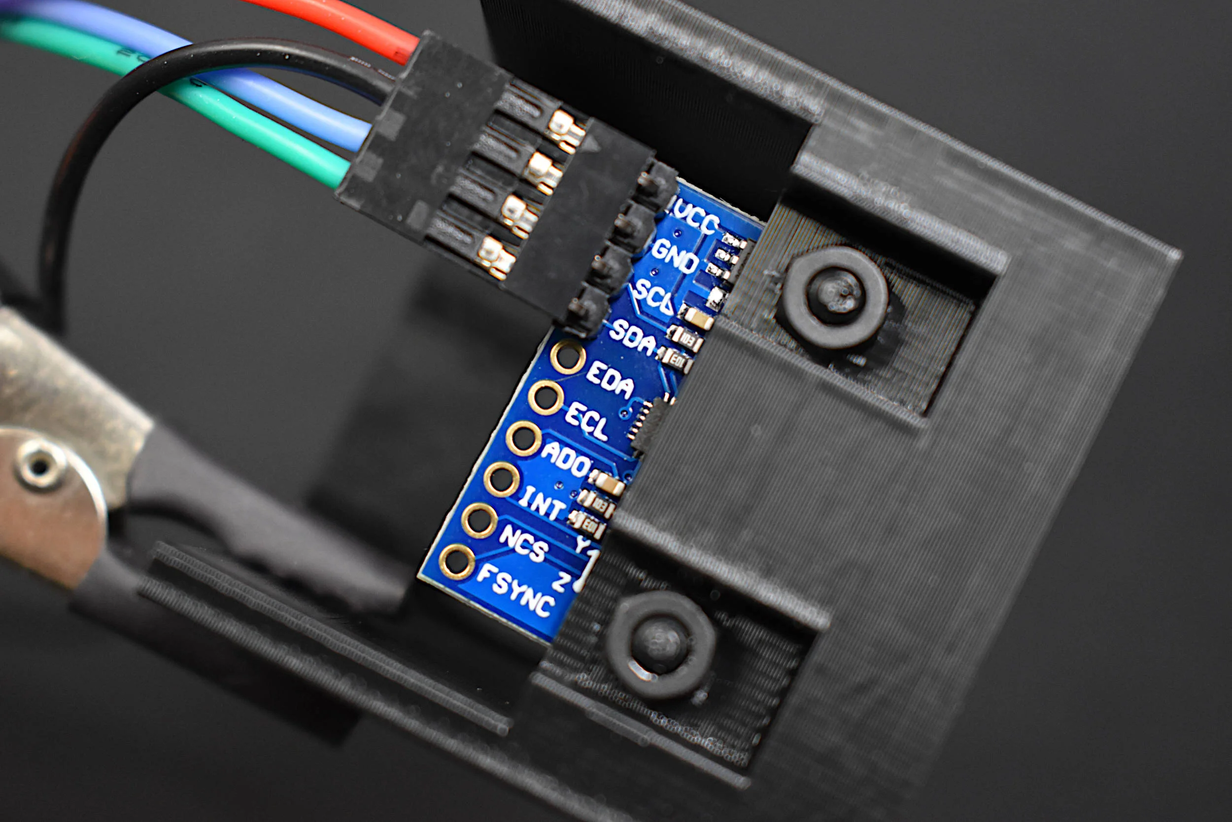
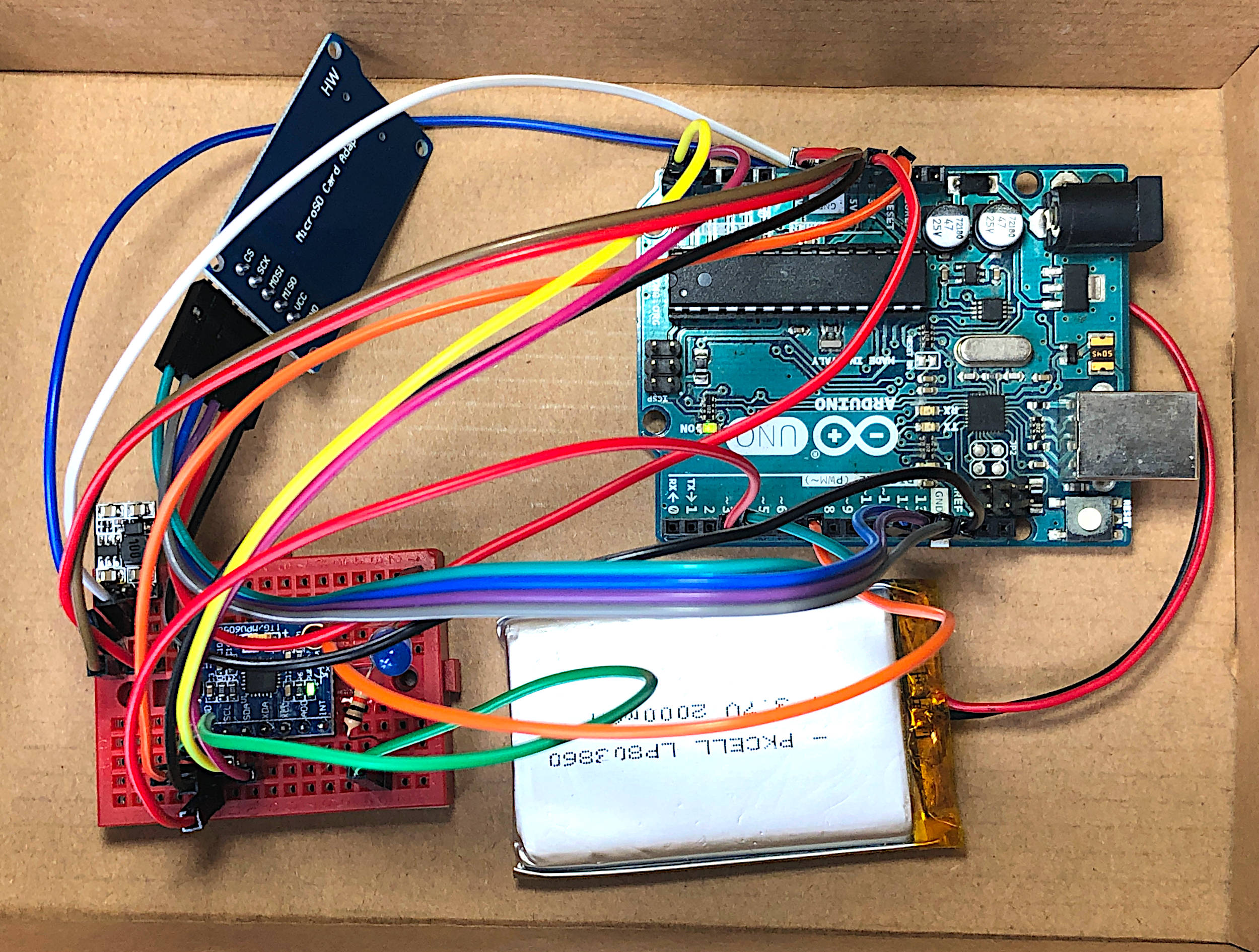
The wiring for the experiments conducted in this tutorial is very minimal and uses I2C wiring for the accelerometer and gyroscope, and SPI wiring for the SD card module. The wiring diagram is given below:
The wiring table is also given below:
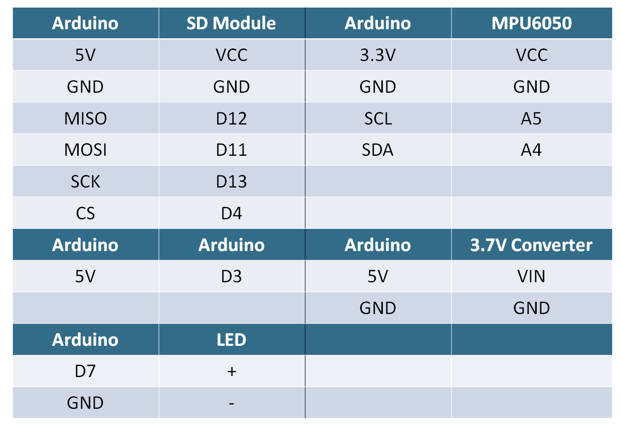
One note regarding the wiring: the Arduino-to-Arduino wiring from 5V to pin D3 is used for letting the program know when to start (HIGH) and stop (LOW) recording. This is important because we will have no other way to notify the program to start and stop. A pullup resistor will be used on pin D3 to limit the power input onto that pin. The rest of the wiring is traditional and expected for the MPU6050 (I2C) and the SD module (SPI). The SD module requires 5V, which is why we’re using a 3.7V to 5V LiPo boost converter. The LED is wired for notifications regarding acquisition of data and processing - this will be discussed in the next section.
The Arduino Uno will be used to acquire acceleration and gyroscopic data from the MPU6050. An Arduino program is given below which automatically acquires data from the MPU6050 at a sample rate of 500Hz and saves it to the SD card. The data acquisition code is based on the SDFat library and its MPU6050 low-latency logger code, except I have cut out the user interface section, which allows us to use the code in a portable manner. In order to use the code, the SDFat library must be downloaded to the Arduino IDE:

The full code (over 500 lines!) is given below:
// Arduino code for high-speed MPU6050 data acquisition with SD module
#include <SPI.h>
#include "SdFat.h"
#include "FreeStack.h"
#include "Wire.h"
#include "I2Cdev.h"
#include "MPU6050.h"

#define FILE_BASE_NAME "mpu6050a" // setting the filename
struct data_t {
  unsigned long time;
  int16_t ax;
  int16_t ay;
  int16_t az;
  int16_t gx;
  int16_t gy;
  int16_t gz;
};
void acquireData(data_t* data);
void printData(Print* pr, data_t* data);
void printHeader(Print* pr);
void userSetup();

MPU6050 mpu;
static uint32_t startMicros;
// Acquire a data record.
void acquireData(data_t* data) {
  data->time = micros();
  mpu.getMotion6(&data->ax, &data->ay, &data->az,
                 &data->gx, &data->gy, &data->gz);
}

// setup AVR I2C
void userSetup() {
#if I2CDEV_IMPLEMENTATION == I2CDEV_ARDUINO_WIRE
  Wire.begin();
  Wire.setClock(400000);
#elif I2CDEV_IMPLEMENTATION == I2CDEV_BUILTIN_FASTWIRE
  Fastwire::setup(400, true);
#endif
  mpu.initialize();
}

// Print a data record.
void printData(Print* pr, data_t* data) {
  if (startMicros == 0) {
    startMicros = data->time;
  }
  pr->print(data->time- startMicros);
  pr->write(',');
  pr->print(data->ax);
  pr->write(',');
  pr->print(data->ay);
  pr->write(',');
  pr->print(data->az);
  pr->write(',');
  pr->print(data->gx);
  pr->write(',');
  pr->print(data->gy);
  pr->write(',');
  pr->println(data->gz);
}

// Print data header.
void printHeader(Print* pr) {
  startMicros = 0;
  pr->println(F("micros,ax,ay,az,gx,gy,gz"));
}

#ifdef __AVR_ATmega328P__
#include "MinimumSerial.h"
MinimumSerial MinSerial;
#define Serial MinSerial
#endif  // __AVR_ATmega328P__
//==============================================================================
// Start of configuration constants.
//==============================================================================
// Abort run on an overrun.  Data before the overrun will be saved.
#define ABORT_ON_OVERRUN 1
//------------------------------------------------------------------------------
//Interval between data records in microseconds.
const uint32_t LOG_INTERVAL_USEC = 2000;
//------------------------------------------------------------------------------
// Set USE_SHARED_SPI non-zero for use of an SPI sensor.
// May not work for some cards.
//#ifndef USE_SHARED_SPI
//#define USE_SHARED_SPI 0
//#endif  // USE_SHARED_SPI
//------------------------------------------------------------------------------
// Pin definitions.
//
// SD chip select pin.
const uint8_t SD_CS_PIN = 4;
const int led_pin = 7;
//
// Digital pin to indicate an error, set to -1 if not used.
// The led blinks for fatal errors. The led goes on solid for
// overrun errors and logging continues unless ABORT_ON_OVERRUN
// is non-zero.
#ifdef ERROR_LED_PIN
#undef ERROR_LED_PIN
#endif  // ERROR_LED_PIN
const int8_t ERROR_LED_PIN = -1;
#define error(msg) {sd.errorPrint(&Serial, F(msg));}

//------------------------------------------------------------------------------
// File definitions.
//
// Maximum file size in blocks.
// The program creates a contiguous file with FILE_BLOCK_COUNT 512 byte blocks.
// This file is flash erased using special SD commands.  The file will be
// truncated if logging is stopped early.
const uint32_t FILE_BLOCK_COUNT = 256000;
//
// log file base name if not defined in UserTypes.h
#ifndef FILE_BASE_NAME
#define FILE_BASE_NAME "data"
#endif  // FILE_BASE_NAME
//------------------------------------------------------------------------------
// Buffer definitions.
//
// The logger will use SdFat's buffer plus BUFFER_BLOCK_COUNT-1 additional
// buffers.
//
#ifndef RAMEND
// Assume ARM. Use total of ten 512 byte buffers.
const uint8_t BUFFER_BLOCK_COUNT = 10;
//
#elif RAMEND < 0X8FF
#error Too little SRAM
//
#elif RAMEND < 0X10FF
// Use total of two 512 byte buffers.
const uint8_t BUFFER_BLOCK_COUNT = 2;
//
#elif RAMEND < 0X20FF
// Use total of four 512 byte buffers.
const uint8_t BUFFER_BLOCK_COUNT = 4;
//
#else  // RAMEND
// Use total of 12 512 byte buffers.
const uint8_t BUFFER_BLOCK_COUNT = 12;
#endif  // RAMEND
//==============================================================================
// End of configuration constants.
//==============================================================================
// Temporary log file.  Will be deleted if a reset or power failure occurs.
#define TMP_FILE_NAME FILE_BASE_NAME "##.bin"

// Size of file base name.
const uint8_t BASE_NAME_SIZE = sizeof(FILE_BASE_NAME) - 1;
const uint8_t FILE_NAME_DIM  = BASE_NAME_SIZE + 7;
char binName[FILE_NAME_DIM] = FILE_BASE_NAME "00.bin";

SdFat sd;

SdBaseFile binFile;

// Number of data records in a block.
const uint16_t DATA_DIM = (512 - 4)/sizeof(data_t);

//Compute fill so block size is 512 bytes.  FILL_DIM may be zero.
const uint16_t FILL_DIM = 512 - 4 - DATA_DIM*sizeof(data_t);

struct block_t {
  uint16_t count;
  uint16_t overrun;
  data_t data[DATA_DIM];
  uint8_t fill[FILL_DIM];
};
//------------------------------------------------------------------------------
//-----------------------------------------------------------------------------
// Convert binary file to csv file.
void binaryToCsv() {
  uint8_t lastPct = 0;
  block_t block;
  uint32_t t0 = millis();
  uint32_t syncCluster = 0;
  SdFile csvFile;
  char csvName[FILE_NAME_DIM];

  if (!binFile.isOpen()) {
    Serial.println();
    Serial.println(F("No current binary file"));
    return;
  }
  Serial.println();
  Serial.print(F("FreeStack: "));
  Serial.println(FreeStack());

  // Create a new csvFile.
  strcpy(csvName, binName);
  strcpy(&csvName[BASE_NAME_SIZE + 3], "csv");

  if (!csvFile.open(csvName, O_WRONLY | O_CREAT | O_TRUNC)) {
    error("open csvFile failed");
  }
  binFile.rewind();
  Serial.print(F("Writing: "));
  Serial.print(csvName);
  Serial.println(F(" - type any character to stop"));
  printHeader(&csvFile);
  uint32_t tPct = millis();
  while (!Serial.available() && binFile.read(&block, 512) == 512) {
    uint16_t i;
    if (block.count == 0 || block.count > DATA_DIM) {
      break;
    }
    if (block.overrun) {
      csvFile.print(F("OVERRUN,"));
      csvFile.println(block.overrun);
    }
    for (i = 0; i < block.count; i++) {
      printData(&csvFile, &block.data[i]);
    }
    if (csvFile.curCluster() != syncCluster) {
      csvFile.sync();
      syncCluster = csvFile.curCluster();
    }
    if ((millis() - tPct) > 1000) {
      uint8_t pct = binFile.curPosition()/(binFile.fileSize()/100);
      if (pct != lastPct) {
        tPct = millis();
        lastPct = pct;
        Serial.print(pct, DEC);
        Serial.println('%');
        digitalWrite(led_pin,HIGH);
        delay(50);
        digitalWrite(led_pin,LOW);
        delay(50);
        digitalWrite(led_pin,HIGH);
        delay(50);
        digitalWrite(led_pin,LOW);
        delay(50);
      }
    }
  }
  csvFile.close();
  Serial.print(F("Done: "));
  Serial.print(0.001*(millis() - t0));
  Serial.println(F(" Seconds"));
}
//-----------------------------------------------------------------------------
void createBinFile() {
  // max number of blocks to erase per erase call
  const uint32_t ERASE_SIZE = 262144L;
  uint32_t bgnBlock, endBlock;

  // Delete old tmp file.
  if (sd.exists(TMP_FILE_NAME)) {
    Serial.println(F("Deleting tmp file " TMP_FILE_NAME));
    if (!sd.remove(TMP_FILE_NAME)) {
      error("Can't remove tmp file");
    }
  }
  // Create new file.
  Serial.println(F("\nCreating new file"));
  binFile.close();
  if (!binFile.createContiguous(TMP_FILE_NAME, 512 * FILE_BLOCK_COUNT)) {
    error("createContiguous failed");
  }
  // Get the address of the file on the SD.
  if (!binFile.contiguousRange(&bgnBlock, &endBlock)) {
    error("contiguousRange failed");
  }
  // Flash erase all data in the file.
  Serial.println(F("Erasing all data"));
  uint32_t bgnErase = bgnBlock;
  uint32_t endErase;
  while (bgnErase < endBlock) {
    endErase = bgnErase + ERASE_SIZE;
    if (endErase > endBlock) {
      endErase = endBlock;
    }
    if (!sd.card()->erase(bgnErase, endErase)) {
      error("erase failed");
    }
    bgnErase = endErase + 1;
  }
}
//------------------------------------------------------------------------------
// dump data file to Serial

//------------------------------------------------------------------------------
// log data
void logData() {
  createBinFile();
  recordBinFile();
  renameBinFile();
}
//------------------------------------------------------------------------------

//------------------------------------------------------------------------------
void recordBinFile() {
  const uint8_t QUEUE_DIM = BUFFER_BLOCK_COUNT + 1;
  // Index of last queue location.
  const uint8_t QUEUE_LAST = QUEUE_DIM - 1;

  // Allocate extra buffer space.
  block_t block[BUFFER_BLOCK_COUNT - 1];

  block_t* curBlock = 0;

  block_t* emptyStack[BUFFER_BLOCK_COUNT];
  uint8_t emptyTop;
  uint8_t minTop;

  block_t* fullQueue[QUEUE_DIM];
  uint8_t fullHead = 0;
  uint8_t fullTail = 0;

  // Use SdFat's internal buffer.
  emptyStack[0] = (block_t*)sd.vol()->cacheClear();
  if (emptyStack[0] == 0) {
    error("cacheClear failed");
  }
  // Put rest of buffers on the empty stack.
  for (int i = 1; i < BUFFER_BLOCK_COUNT; i++) {
    emptyStack[i] = &block[i - 1];
  }
  emptyTop = BUFFER_BLOCK_COUNT;
  minTop = BUFFER_BLOCK_COUNT;

  // Start a multiple block write.
  if (!sd.card()->writeStart(binFile.firstBlock())) {
    error("writeStart failed");
  }
  Serial.print(F("FreeStack: "));
  Serial.println(FreeStack());
  Serial.println(F("Logging - type any character to stop"));
  bool closeFile = false;
  uint32_t bn = 0;
  uint32_t maxLatency = 0;
  uint32_t overrun = 0;
  uint32_t overrunTotal = 0;
  uint32_t logTime = micros();
  while(1) {
     // Time for next data record.
    logTime += LOG_INTERVAL_USEC;
    if (digitalRead(3)==LOW) {
      closeFile = true;
    }
    if (closeFile) {
      if (curBlock != 0) {
        // Put buffer in full queue.
        fullQueue[fullHead] = curBlock;
        fullHead = fullHead < QUEUE_LAST ? fullHead + 1 : 0;
        curBlock = 0;
      }
    } else {
      if (curBlock == 0 && emptyTop != 0) {
        curBlock = emptyStack[--emptyTop];
        if (emptyTop < minTop) {
          minTop = emptyTop;
        }
        curBlock->count = 0;
        curBlock->overrun = overrun;
        overrun = 0;
      }
      if ((int32_t)(logTime - micros()) < 0) {
        error("Rate too fast");
      }
      int32_t delta;
      do {
        delta = micros() - logTime;
      } while (delta < 0);
      if (curBlock == 0) {
        overrun++;
        overrunTotal++;
        if (ERROR_LED_PIN >= 0) {
          digitalWrite(ERROR_LED_PIN, HIGH);
        }
#if ABORT_ON_OVERRUN
        Serial.println(F("Overrun abort"));
        break;
 #endif  // ABORT_ON_OVERRUN
      } else {
#if USE_SHARED_SPI
        sd.card()->spiStop();
#endif  // USE_SHARED_SPI
        acquireData(&curBlock->data[curBlock->count++]);
#if USE_SHARED_SPI
        sd.card()->spiStart();
#endif  // USE_SHARED_SPI
        if (curBlock->count == DATA_DIM) {
          fullQueue[fullHead] = curBlock;
          fullHead = fullHead < QUEUE_LAST ? fullHead + 1 : 0;
          curBlock = 0;
        }
      }
    }
    if (fullHead == fullTail) {
      // Exit loop if done.
      if (closeFile) {
        break;
      }
    } else if (!sd.card()->isBusy()) {
      // Get address of block to write.
      block_t* pBlock = fullQueue[fullTail];
      fullTail = fullTail < QUEUE_LAST ? fullTail + 1 : 0;
      // Write block to SD.
      uint32_t usec = micros();
      if (!sd.card()->writeData((uint8_t*)pBlock)) {
        error("write data failed");
      }
      usec = micros() - usec;
      if (usec > maxLatency) {
        maxLatency = usec;
      }
      // Move block to empty queue.
      emptyStack[emptyTop++] = pBlock;
      bn++;
      if (bn == FILE_BLOCK_COUNT) {
        // File full so stop
        break;
      }
    }
  }
  if (!sd.card()->writeStop()) {
    error("writeStop failed");
  }
  Serial.print(F("Min Free buffers: "));
  Serial.println(minTop);
  Serial.print(F("Max block write usec: "));
  Serial.println(maxLatency);
  Serial.print(F("Overruns: "));
  Serial.println(overrunTotal);
  // Truncate file if recording stopped early.
  if (bn != FILE_BLOCK_COUNT) {
    Serial.println(F("Truncating file"));
    if (!binFile.truncate(512L * bn)) {
      error("Can't truncate file");
    }
  }
}
//------------------------------------------------------------------------------
void recoverTmpFile() {
  uint16_t count;
  if (!binFile.open(TMP_FILE_NAME, O_RDWR)) {
    return;
  }
  if (binFile.read(&count, 2) != 2 || count != DATA_DIM) {
    error("Please delete existing " TMP_FILE_NAME);
  }
  Serial.println(F("\nRecovering data in tmp file " TMP_FILE_NAME));
  uint32_t bgnBlock = 0;
  uint32_t endBlock = binFile.fileSize()/512 - 1;
  // find last used block.
  while (bgnBlock < endBlock) {
    uint32_t midBlock = (bgnBlock + endBlock + 1)/2;
    binFile.seekSet(512*midBlock);
    if (binFile.read(&count, 2) != 2) error("read");
    if (count == 0 || count > DATA_DIM) {
      endBlock = midBlock - 1;
    } else {
      bgnBlock = midBlock;
    }
  }
  // truncate after last used block.
  if (!binFile.truncate(512*(bgnBlock + 1))) {
    error("Truncate " TMP_FILE_NAME " failed");
  }
  renameBinFile();
}
//-----------------------------------------------------------------------------
void renameBinFile() {
  while (sd.exists(binName)) {
    if (binName[BASE_NAME_SIZE + 1] != '9') {
      binName[BASE_NAME_SIZE + 1]++;
    } else {
      binName[BASE_NAME_SIZE + 1] = '0';
      if (binName[BASE_NAME_SIZE] == '9') {
        error("Can't create file name");
      }
      binName[BASE_NAME_SIZE]++;
    }
  }
  if (!binFile.rename(binName)) {
    error("Can't rename file");
    }
  Serial.print(F("File renamed: "));
  Serial.println(binName);
  Serial.print(F("File size: "));
  Serial.print(binFile.fileSize()/512);
  Serial.println(F(" blocks"));
}
//------------------------------------------------------------------------------

//------------------------------------------------------------------------------
void setup(void) {
  Serial.begin(9600);
  pinMode(3,INPUT_PULLUP); // used for starting/stopping recording
  pinMode(led_pin,OUTPUT);

  // Allow userSetup access to SPI bus.
  pinMode(SD_CS_PIN, OUTPUT);
  digitalWrite(SD_CS_PIN, HIGH);

  // Setup sensors.
  userSetup();

  // Initialize at the highest speed supported by the board that is
  // not over 50 MHz. Try a lower speed if SPI errors occur.
  if (!sd.begin(SD_CS_PIN, SD_SCK_MHZ(50))) {
    sd.initErrorPrint(&Serial);
  }
}

void loop(void) {
  if (digitalRead(3)==HIGH){
    digitalWrite(led_pin,HIGH);
    Serial.println("Recording Data...");
    logData();
    binaryToCsv();
    digitalWrite(led_pin,LOW);
    Serial.println(""); Serial.println("Saved .csv file");
    Serial.println("");
  } else {
    Serial.println("Change Digital Pin 3 to HIGH to Record Data...");
    delay(3000);
  }

}
There isn’t much to say about the code without creating an entire post about the methods used in it. Therefore, I leave the code analysis to the user. Most of it is not mine, rather it was developed by the SDFat folks, so this is the extent to which I will explore it. I will, however, continue to discuss the notifications and outputs of the code, which will be necessary for acquiring and analyzing the data.
The general process flow followed by the code is as follows:
PIN 3
HIGH -> Acquire Data (LED HIGH)
While PIN 3 is HIGH data is acquired and stored in binary format for efficiency (500 Hz sample rate)
PIN 3 goes LOW, data enters conversion mode to .csv format
LED blinks during this process - DO NOT eject SD card or power off Arduino
LED will stop blinking and go LOW - Now, we go back to the beginning of this tree flow
LOW -> Do Nothing
The following should be the sequence for acquiring data:
Put PIN 3 LOW
Power on Arduino with LiPo battery
PIN 3 HIGH (acquire data)
PIN 3 LOW (convert data to .csv)
Wait for LED to stop blinking and go LOW
Power off Arduino
Eject SD card
NOTE:
The LED may blink for the same amount of time as the acquisition. The Arduino works at the highest frequency possible during acquisition, so the conversion can be lengthy due to the high sample rate (500Hz). If the MPU6050 is acquiring data for ten minutes, it may take just as long to convert - so patience is key.
Now we’re ready to analyze the data!
The output file should be named as follows:
mpu6050a00.csv
where the last two digits of the file name iterate up as more files are created on one SD card. Once the SD card is inserted into a desktop computer via the USB drive, we can open one of the files with a Python program. An example Python scripe to do this is given below:
## Python code for reading MPU6050 data saved to .csv file
import csv
import numpy as np
import matplotlib.pyplot as plt

plt.style.use('ggplot') # plot formatting

# .csv reader algorithm
csv_filename = 'mpu6050a02.csv'
data_headers = []
time_vec = []
accel_x,accel_y,accel_z,gyro_x,gyro_y,gyro_z = [],[],[],[],[],[]
with open(csv_filename,newline='') as csvfile:
    csvreader = csv.reader(csvfile,delimiter=",")
    for row in csvreader:
        if data_headers==[]:
            data_headers = row
            continue
        time_vec.append(float(row[0]))
        accel_x.append(float(row[1]))
        accel_y.append(float(row[2]))
        accel_z.append(float(row[3]))
        gyro_x.append(float(row[4]))
        gyro_y.append(float(row[5]))
        gyro_z.append(float(row[6]))

time_vec = np.divide(time_vec,1000000.0) # correct for microseconds -> seconds

samp_rate = len(time_vec)/(time_vec[-1]-time_vec[0]) # psuedo sample rate
print('Sample Rate:  Hz'.format(samp_rate))

## conversion from bits to real-world values
accel_factor = ((2.0**15.0)-1.0)/2.0 # conversion using sensitivity (+- 2g)
gyro_factor = ((2.0**15.0)-1.0)/250.0 # conversion using sensitivity (250 deg/sec)

accel_x = np.array(accel_x)/accel_factor
accel_y = np.array(accel_y)/accel_factor
accel_z = np.array(accel_z)/accel_factor

gyro_x = np.array(gyro_x)/gyro_factor
gyro_y = np.array(gyro_y)/gyro_factor
gyro_z = np.array(gyro_z)/gyro_factor

## subplot with accel + gyro raw data after conversion
fig,ax = plt.subplots(2,1,figsize=(12,9))

ax1 = ax[0] # accel axis
cmap = plt.cm.Set1
ax1.plot(time_vec,accel_x,label='x-Acceleration',color=cmap(0),linewidth=4)
ax1.plot(time_vec,accel_y,label='y-Acceleration',color=cmap(1),linewidth=4)
ax1.plot(time_vec,accel_z,label='z-Acceleration',color=cmap(2),linewidth=4)
ax1.legend(fontsize=16)
ax1.set_ylabel('Acceleration [m $\cdot$ s$^$]',fontsize=16)

ax2 = ax[1] # gyro axis
cmap = plt.cm.tab10
ax2.plot(time_vec,gyro_x,label='x-gyroscope',color=cmap(1),linewidth=4)
ax2.plot(time_vec,gyro_y,label='y-gyroscope',color=cmap(4),linewidth=4)
ax2.plot(time_vec,gyro_z,label='z-gyroscope',color=cmap(6),linewidth=4)
ax2.legend(fontsize=16)
ax2.set_ylabel('Degrees [$^\circ$]',fontsize=16)
plt.xlabel('Time [s]',fontsize=16)
plt.savefig('mpu6050_subplot_accel_gyro_test.png',dpi=200,facecolor=[252/255,252/255,252/255]) # uncomment to save figure
plt.show()
If the MPU6050 is not moved and it remains on its horizontal axis (with the z-axis pointed toward the ground - in the direction of gravity), we should see an output similar to the one shown below (plotted using the code given above):

We can see in the figure how the z-direction shows 1 (indicating that it is constantly experiencing the effect of gravity). The other accelerations are near zero. All gyroscope x,y,z values are zero, because we have not rotated the device at all. Toward the 13 second mark in the plot, we see some disturbance, which is a result of switching the acquisition pin from LOW to HIGH, and slightly disturbing the module. Below, the MPU6050 will be rotated to test and identify each axis of the accelerometer and gyroscope, which will give us a better idea of how the given axes function.
Once the acclerometer and gyroscope data is acquired, we must create an offset or calibration method for ensuring that accelerations and gyroscopic movements are tracked properly and with reference to the physical world. The best method for offsetting MPU6050 data is to assume the device starts at rest (which is a fine assumption for users who are aware of this). Therefore, using the data above, we can offset the data by subtracting the motionless data (I average over a few points) from the rest of the data. We also must take note of the gravitational influence and direction of gravity (z-direction in our case, assuming it adds to 1).
We now expect all the points in the beginning of the data plot to be centered about zero:

The offset code is incorporated in the Python code below:
## Python code for reading MPU6050 data and calculating offset values
import csv
import numpy as np
import matplotlib.pyplot as plt

plt.style.use('ggplot') # plot formatting

##########################
# .csv reader algorithm
##########################

csv_filename = 'mpu6050a02.csv'
data_headers = []
time_vec = []
accel_x,accel_y,accel_z,gyro_x,gyro_y,gyro_z = [],[],[],[],[],[]
with open(csv_filename,newline='') as csvfile:
    csvreader = csv.reader(csvfile,delimiter=",")
    for row in csvreader:
        if data_headers==[]:
            data_headers = row
            continue
        time_vec.append(float(row[0]))
        accel_x.append(float(row[1]))
        accel_y.append(float(row[2]))
        accel_z.append(float(row[3]))
        gyro_x.append(float(row[4]))
        gyro_y.append(float(row[5]))
        gyro_z.append(float(row[6]))

time_vec = np.divide(time_vec,1000000.0) # correct for microseconds -> seconds
samp_rate = len(time_vec)/(time_vec[-1]-time_vec[0]) # psuedo sample rate
print('Sample Rate:  Hz'.format(samp_rate))

##########################
## conversion from bits to real-world values
##########################

accel_factor = ((2.0**15.0)-1.0)/2.0 # conversion using sensitivity (+- 2g)
gyro_factor = ((2.0**15.0)-1.0)/250.0 # conversion using sensitivity (250 deg/sec)

accel_x = np.array(accel_x)/accel_factor
accel_y = np.array(accel_y)/accel_factor
accel_z = np.array(accel_z)/accel_factor

gyro_x = np.array(gyro_x)/gyro_factor
gyro_y = np.array(gyro_y)/gyro_factor
gyro_z = np.array(gyro_z)/gyro_factor

##########################
## Offset methods
##########################
cal_start = 0 # start calibration point
cal_end = 100 # end calibration point

# accel calibrations
a_x_cal = accel_x[cal_start:cal_end]
a_y_cal = accel_y[cal_start:cal_end]
a_z_cal = accel_z[cal_start:cal_end]
# gyro calibrations
g_x_cal = gyro_x[cal_start:cal_end]
g_y_cal = gyro_y[cal_start:cal_end]
g_z_cal = gyro_z[cal_start:cal_end]

# calculate accel & gyro calibration means
accel_offsets = [np.mean(a_x_cal),np.mean(a_y_cal),np.mean(a_z_cal)]
gyro_offsets = [np.mean(g_x_cal),np.mean(g_y_cal),np.mean(g_z_cal)]

grav_direc = np.argmax(accel_offsets) # location of gravity

# actual calculation of offset (subtracting starting means)
accel_x = accel_x-accel_offsets[0]
accel_y = accel_y-accel_offsets[1]
accel_z = accel_z-accel_offsets[2]

gyro_x = gyro_x-gyro_offsets[0]
gyro_y = gyro_y-gyro_offsets[1]
gyro_z = gyro_z-gyro_offsets[2]

##########################
## subplot with accel + gyro raw data after conversion
##########################

fig,ax = plt.subplots(2,1,figsize=(12,9))

ax1 = ax[0] # accel axis
cmap = plt.cm.Set1
ax1.plot(time_vec,accel_x,label='x-Acceleration',color=cmap(0),linewidth=4)
ax1.plot(time_vec,accel_y,label='y-Acceleration',color=cmap(1),linewidth=4)
ax1.plot(time_vec,accel_z,label='z-Acceleration',color=cmap(2),linewidth=4)
ax1.legend(fontsize=16)
ax1.set_ylabel('Acceleration [m $\cdot$ s$^$]',fontsize=16)

ax2 = ax[1] # gyro axis
cmap = plt.cm.tab10
ax2.plot(time_vec,gyro_x,label='x-gyroscope',color=cmap(1),linewidth=4)
ax2.plot(time_vec,gyro_y,label='y-gyroscope',color=cmap(4),linewidth=4)
ax2.plot(time_vec,gyro_z,label='z-gyroscope',color=cmap(6),linewidth=4)
ax2.legend(fontsize=16)
ax2.set_ylabel('Degrees [$^\circ$]',fontsize=16)
plt.xlabel('Time [s]',fontsize=16)
##plt.savefig('mpu6050_offset_cal.png',dpi=200,facecolor=[252/255,252/255,252/255]) # uncomment to save figure
plt.show()
And now we can start our analysis of accelerometer and gyroscope data. Better methods for offsetting and calibrating the accelerometer data will be explored, but at this time we need to acquire more meaningful data and analyze the acceleration and rotation using relevant algorithms and more advanced mathematics.
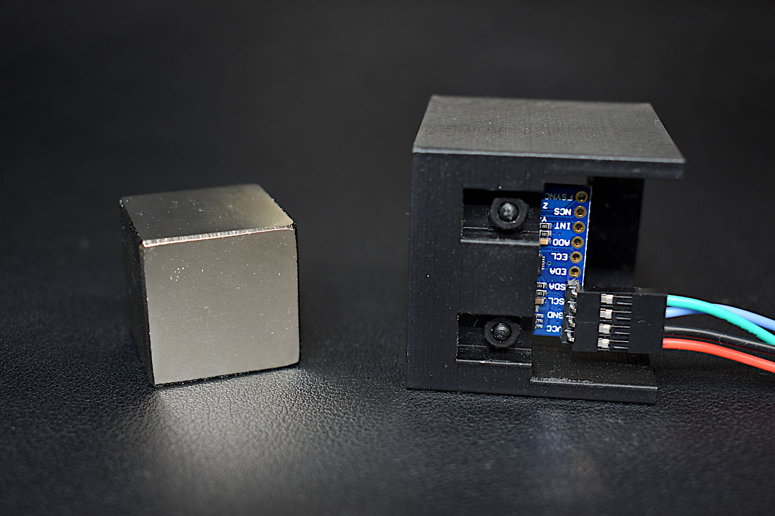
We can start by carrying out the following experiment:
Briefly rotate and hold the MPU6050 on each of its axes (x,y, and z) - this will ensure better calculation of offset with respect to gravity
Rotate the MPU6050 clockwise and then couter-clockwise on each axis - this will allow us to determine the degree of rotation for the gyroscope
The resulting data output should look as follows:

Now this might look like a bit of a mess, but the rotations and resulting accelerations and angles endow us with the information needed for complete calibration of the sensor.
First, we can see that the accelerations due to gravity are not quite 1 in each direction, meaning that our sensor is likely slightly angled. This is not an issue - as we can correct for it under the assumption of a uniform field of gravitation (accurate on earth in a stationary position). We can do this by selecting a steady section during each axis’s rotation in the direction of gravity, then finding the deficit in gravitational acceleration for each axis.
The MPU6050 6-Dof accelerometer and gyroscope was introduced and explored using Arduino as a high-speed data acquisition system. An SD module was used to save acceleration and gyroscopic information at a rate of 500 Hz (with the Arduino Uno board). I introduced a simple wiring method to acquire the 6-DoF inertial measurements, which were later analyzed using a Python program. With Python, we were able to read the accelerometer and gyroscope information using the csv reader library. The inertial data was then plotted for visualization and offset using a calibration technique harnessing the acceleration due to gravity (for the accelerometer offset values). This tutorial merely introduced the 6-DoF MPU6050 sensor, which will be further elaborated-upon in the next entry in the analysis using Python.
See More in Sensors and Python: