An Introduction to the Raspberry Pi Pico with MicroPython
“As an Amazon Associates Program member, clicking on links may result in Maker Portal receiving a small commission that helps support future projects.”
The Raspberry Pi Pico was recently released by the Raspberry Pi Foundation as a competitive microcontroller in the open-source electronics sphere. The Pico shares many of the capabilities of common Arduino boards including: analog-to-digital conversion (12-bit ADC), UART, SPI, I2C, PWM, among others. The board is just 21mm x 51mm in size, making it ideal for applications that require low-profile designs. One of the innovations of the Pico is the dual-core processor, which permits multiprocessing at clock rates up to 133 MHz. One particular draw of the Pico is its compatibility with MicroPython, which is chosen as the programming tool for this project. The focus on MicroPython, as opposed to C/C++, minimizes the confusion and time required to get started with the Pico. A Raspberry Pi 4 computer is ideal for interfacing with the Pico, which can be used to prepare, debug, and program the Pico. From start to finish - this tutorial helps users run their first custom MicroPython script on the Pico in just a few minutes. An RGB LED will be used to demonstrate general purpose input/output of the Pico microcontroller.
A Raspberry Pi Pico and Raspberry Pi 4 computer are the minimum required components for testing the Pico. The Pico has an onboard LED that can be controlled and used to test the basic functionality of the microcontroller. However, we want to test the capabilities on an external piece of hardware. An RGB LED will be used to test the general purpose inputs/outputs (GPIOs) of the Pico along with pulse-width modulation (PWM) for adjusting the brightness of the LED(s). A half breadboard (mini breadboards are too small) will also be used for our testing of the RGB LED. The full parts list is given below to follow along with the tutorial:
1x Raspberry Pi Pico Starter Kit (Breadboard, RGB LED, USB Cable)- $15.00 [Our Store]
1x Raspberry Pi 4 Computer - $51.99 (2GB), $61.89 (4GB), $89.99 (8GB) [Amazon], $55.00 [2GB from Our Store]
1x RGB LED - $3.00 [Our Store]
4x Jumper Wires (Male-to-Male) - $0.60 [Our Store]
1x Half Breadboard (400 ties) - $6.00 [Our Store]
The Raspberry Pi Pico is a new microcontroller designed by the Raspberry Pi foundation. The Pico is a groundbreaking board that is meant to use MicroPython in its native micro USB port. The RP2040 is the microcontroller chip at the center of the Pico, which has a dual-core Arm Cortex M0+ processor, capable of clocking at 133 MHz, which is much faster than many of the Arduino boards currently on the market. The Pico has GPIO pins and interfaces such as: SPI, UART, I2C, PWM, and a 12-bit analog-to-digital converter (ADC). This Raspberry Pi Pico Kit comes with the Pico microcontroller, an RGB LED, a breadboard, jumper wires, and USB cable.
Included in the Raspberry Pi Pico Starter Kit:
1x Raspberry Pi Pico Board
2x 20-pin Headers
1x Black 0.5m Micro USB Cable
1x RGB LED
4x Male-to-Male Jumpers
1x Half Breadboard (White)
Features of the Raspberry Pi Pico:
1.8V - 5.5V Input Voltage
21 mm × 51 mm Board Geometry
RP2040 microcontroller
Dual-core Arm Cortex-M0+ processor (Clock Speed up to 133 MHz)
264KB on-chip SRAM, 2MB on-board QSPI Flash
26x GPIO pins (3x 12-bit Analog Inputs)
2x UART, 2x SPI, 2x I2C, 16x PWM
1x USB 1.1 controller and PHY, with host and device support
8x Programmable I/O (PIO) state machines for custom peripheral support
Operating temperature -20°C to +85°C
Low-power sleep and dormant modes
Onboard Temperature sensor
Accelerated integer and floating-point libraries on-chip
NOTE: Our batch of RGB LED modules have reversed labels for green and red, meaning, the label R is for green, and G is for red. This was noticed after receiving and testing the modules from our manufacturer.
Note that the Raspberry Pi Pico Starter Kit, in conjunction with a Raspberry Pi 4 computer, are the only required parts for this tutorial!
The pinout diagram for the Raspberry Pi Pico is given below for reference:

The pinout diagram will be essential for testing the Pico and determining which GPIO pins will be used to control the RGB LED.
The RP2040 microcontroller is at the center of the Raspberry Pi Pico. The RP2040 has a native MicroPython port and a USB Flashing Format (UF2) bootloader in its memory, meaning that the Pico can directly handle Python code uploaded via an IDE. Thonny will be used as the IDE on the Raspberry Pi 4 computer, which is already installed on newer Raspberry Pi OS distributions.
The MicroPython ‘Getting Started’ guide on the Raspberry Pi Pico webpage is used as the template for much of the MicroPython and Pico startup that follows. The following screenshots summarize the process required for preparing the Pico for MicroPython programming with Thonny:
Step 1: Download the MicroPython UF2 File for the Pico
Also downloadable on the Pico Webpage
Step 2: Hold Down BOOTSEL and Connect Pico to USB Port on Raspberry Pi 4
The Pico should now be shown as a mass storage device on the Raspberry Pi 4 desktop. The name of the device should be RPI-RP2, which represents the RP2040 microcontroller.

Step 3: Verify the RPI-RP2 Device in the File Manger
Next, drag and drop the downloaded UF2 file containing the MicroPython distribution onto be onto the RPI-RP2 device:

Step 4: Drag and Drop the Downloaded MicroPython UF2 File to the RPI-RP2 (Pico) Device
RPI-RP2 is the Pico Mass Storage Device Name, which should disappear after dragging and dropping the UF2 file onto it
At this point, the Pico is ready to function as a MicroPython-enabled device. The device is now acting as a microcontroller ready to be programmed using Python.
We can now check that Python is working on the Pico by testing its command line interface with minicom. First, make sure ‘minicom’ is installed on the RPi via the terminal:
pi@raspberrypi:~ $ sudo apt-get install minicom
Once minicom is installed, verify the location of the Pico microcontroller using the following command in the terminal:
pi@raspberrypi:~ $ ls /dev/tty*
The Pico can be found by unplugging and running the command above, and then plugging in the Pico and running the command again and looking for the changed port. The Pico is most likely on port /dev/ttyACM1, if no other devices are connected. The Pico port will appear as shown below:
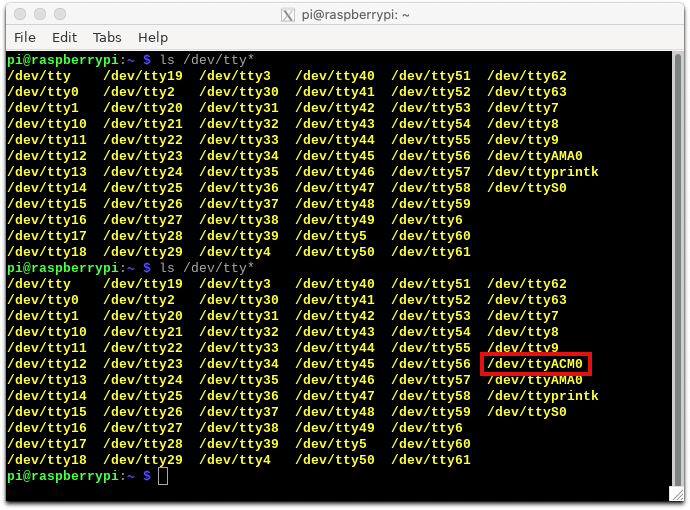
Discovery of The Pico Device Port (ttyACM0)
Before and after plugging the Pico into the USB port
Now we can verify the communication between the Raspberry Pi and Pico microcontroller using minicom commands to gain access to the Python terminal:
pi@raspberrypi:~ $ minicom -o -D /dev/ttyACM0
The resulting minicom menu should appear:

Minicom Menu on the Pico Microcontroller
Pressing “Enter” takes the user into the Python terminal, where the user can control the Pico microcontroller using Python commands
The first real test we can do at this point is turn on the onboard LED via a series of commands:

Toggling the Onboard Pico LED to Its On State
The onboard LED should be on after the three lines of Python code are inputted
The three lines of code are:
>>>from machine import Pin
>>>led = Pin(25,Pin.OUT)
>>>led.high()
Similarly, if the led variable is then set to led.low() - the onboard LED will be turned off.

Now that MicroPython is working on the Pico, we can move on to more robust programming with Python on the Pico. The way we do this is by working with the Thonny IDE on the Raspberry Pi. Most distributions of Raspberry Pi OS have an installation of Thonny included in the first boot of the OS. However, if a headless or lite version is being used, Thonny will need to be installed. This can be done via ‘sudo pip3 install thonny.’ Going forward, it is assumed that Thonny is already installed on the Raspberry Pi. First, open Thonny and look for the ‘Tools’ menu at the toolbar:

Open Thonny on The Raspberry Pi
Switch to regular mode if no toolbar is available, then exit and reopen the IDE
If the Thonny IDE looks similar to the one above, click ‘Switch to regular mode’ and then exit and reopen the IDE.

The Correct Thonny Window with The Enabled Toolbar
Note the Shell indicating Python 3. This will be changed to MicroPython on the Pico.
Next, we will tell Thonny to use the Raspberry Pi Pico as the Interpreter, which can be done as follows:

Navigate to Tools -> Options

Select Interpreter and Choose ‘MicroPython (Raspberry Pi Pico)’ to Use The Pico with Thonny
Now, the Thonny shell can be used in a similar manner as the minicom interface. Returning to the three lines of code that control the Pico’s onboard LED, we can test the MicroPython interpreter on the Pico:
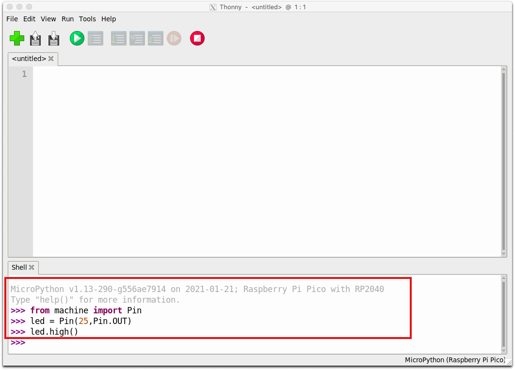
Confirm MicroPython in The Thonny Shell
The MicroPython interpreter can also be verified by turning on the Pico’s LED in the shell
The advantage of using Thonny is that it allows for scripting and live software debugging. A script can also be uploaded to the Pico under the name ‘main.py’ and it will run in an infinite loop similar to the loop() running indefinitely on an Arduino microcontroller. In the next section, a script will be developed that controls the red, green, and blue components of an RGB LED using the general purpose inputs/outputs (GPIOs) on the Pico.
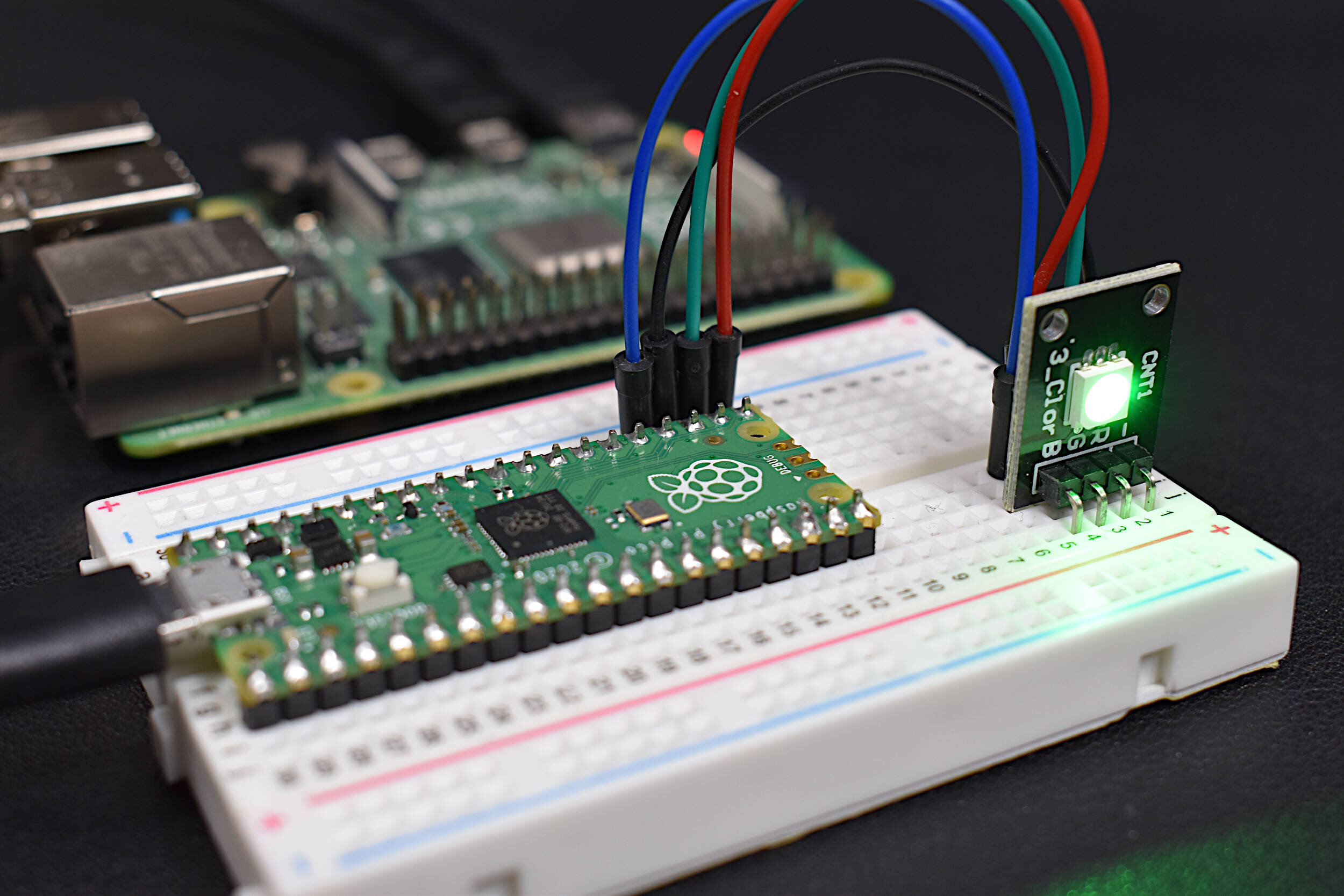
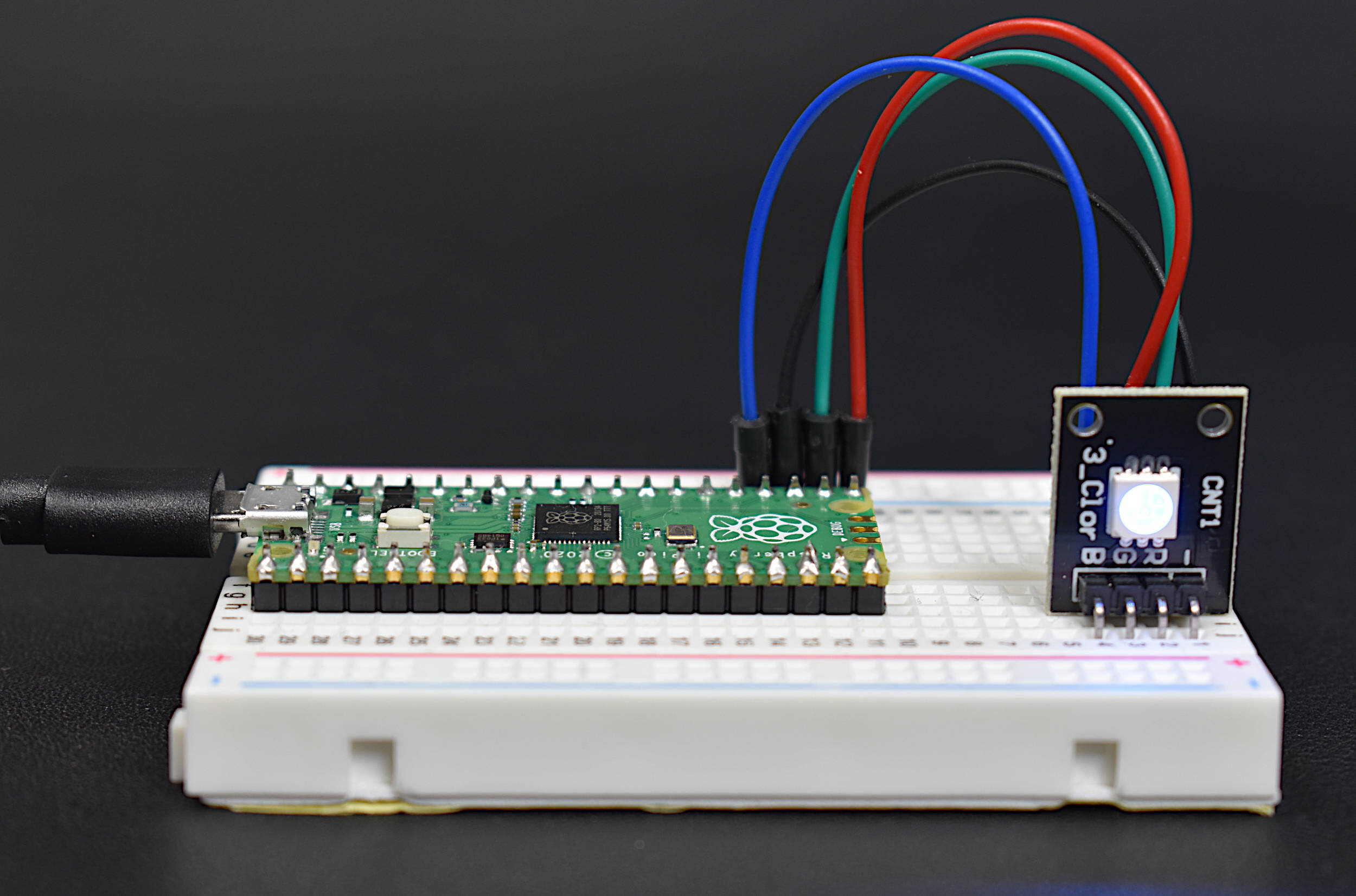
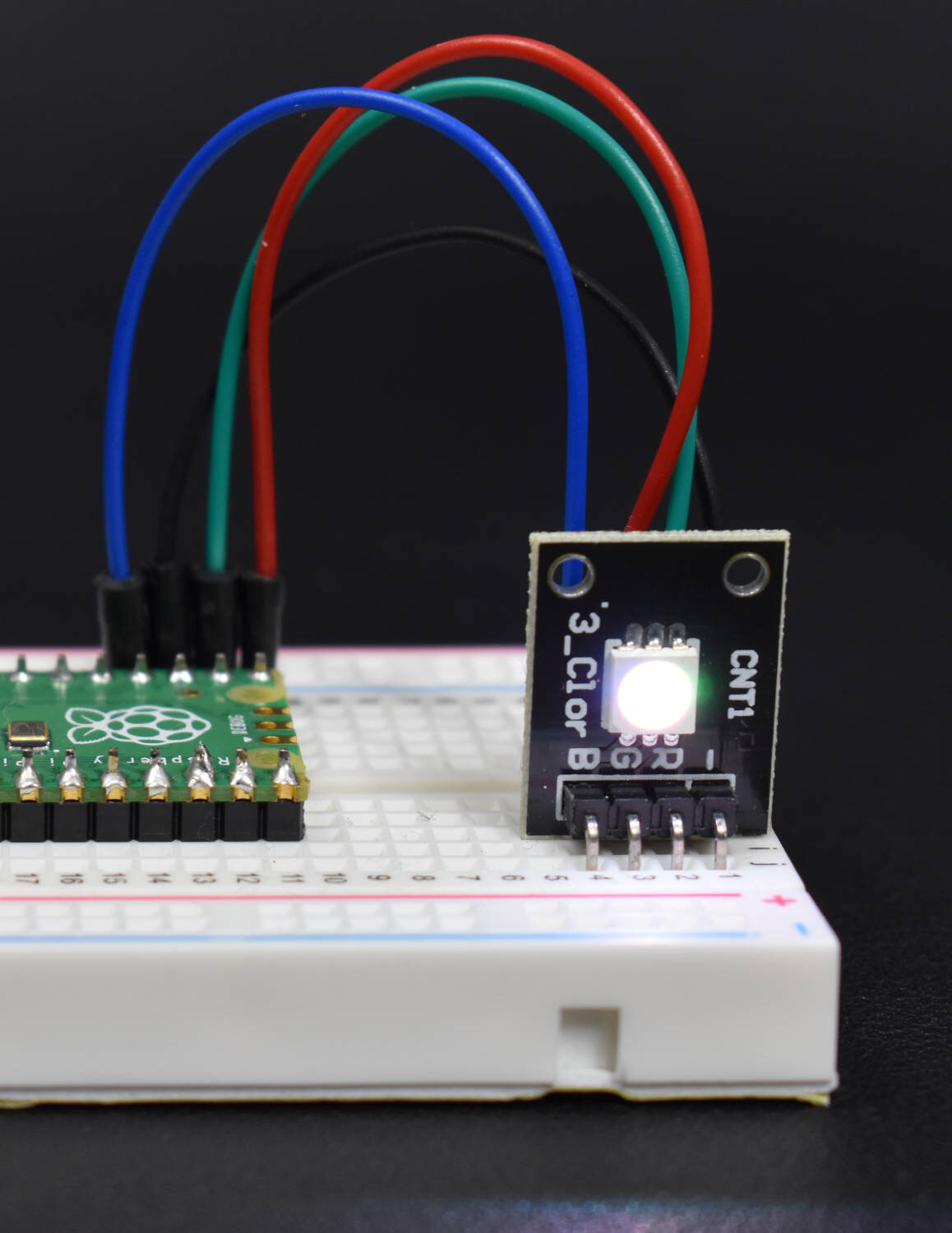
The general purpose input/output (GPIO) pins on the Pico microcontroller will be tested by developing a script that adjusts the brightness of the components on an RGB LED using two types of control: boolean and pulse-width modulation (PWM). The boolean control turns each LED on and off with a high and low designation. The PWM control uses a duty cycle modulation to control the brightness of the LEDs.
RGB LED to Raspberry Pi Pico Wiring Diagram

GPIOs 16-18 Wired to the Red, Green, and Blue LED Pins
Pin 23 is used as ground
FS Tech can help makers with its turnkey PCB assembly expertise, from design to packaging. Choosing a turnkey PCB assembly company can make your project easier, sleeker, and save you work in your future projects.

The script below is used to turn each LED on and then off in an infinite loop:
################################
# RGB LED Tests on the RPi Pico
#
# Copyright (c) Maker Portal LLC
# Author: Joshua Hrisko
################################
#
from machine import Pin
import time

led_pins = [16,17,18] # pins where RGB LED is wired
leds = [Pin(led_pins[0],Pin.OUT),Pin(led_pins[1],Pin.OUT),
        Pin(led_pins[2],Pin.OUT)] # pin control array
delay_t = 0.1 # seconds to delay between toggles
while True: # loop infinitely
    for led in leds: # loop through each led
        led.high() # led high
        time.sleep(delay_t) # wait
        led.low() # led low
        time.sleep(delay_t) # wait
The code above should be inputted into the <untitled> script portion of the Thonny IDE.
Procedure for uploading code to the Pico microcontroller:
- Press F5 or the Run Button
- Select 'Raspberry Pi Pico' as the Save Location
- Name the File 'main.py' to run the script indefinitely on the Pico
- Click OK and Observe the Script Running (LED Blink Loop)

Saving the Script as ‘main.py’ Will Run the Script Immediately After the Pico Boots
Saving the script as another name will save it to the Pico, but will only run when instructed to (via Minicom or Thonny).
A video demonstration of the RGB LED looping is shown below:
Next, we can test the pulse-width modulation (PWM) functions of the Pico by adjusting the brightness of each LED on the RGB LED. Specifically, the LED can be made to appear as ‘breathing’ by increasing and decreasing its brightness. The code to do this is given below:
################################
# Pico PWM Control of RGB LED
#
# Copyright (c) Maker Portal LLC
# Author: Joshua Hrisko
################################
#
import time
from machine import Pin,PWM

pwm_pins = [16,17,18] # set PWM pins
pwms = [PWM(Pin(pwm_pins[0])),PWM(Pin(pwm_pins[1])),
                PWM(Pin(pwm_pins[2]))] # pwm array
[pwm.freq(1000) for pwm in pwms] # set pwm freqs

step_val = 64 # step value for 16-bit breathing
range_0 = [ii for ii in range(0,2**16,step_val)] # brightening
range_1 = [ii for ii in range(2**16,-step_val,-step_val)] # dimming

while True: # loop indefinitely
    # looping through red, blue, green breathing
    for pwm in pwms:
           for ii in range_0+range_1:
               pwm.duty_u16(ii) # set duty cycle out of 16-bits
               time.sleep(0.001) # sleep 1ms between pwm change
    # white pixel breathing (all three LEDs)
    for ii in range_0+range_1:
        for pwm in pwms:
            pwm.duty_u16(ii) # set duty cycle
        time.sleep(0.001) # wait 1ms
Similar to the code above, be sure to select F5 or Run and save the file as the new ‘main.py’ file on the Pico. This will again cause the script to run indefinitely, resulting in an endless ‘breathing’ appearance form the RGB LED.
The frequency of the PWM pulse was set to 1000Hz (1kHz), which is similar to some Arduino boards. 500Hz can also be used as other Arduino boards/pins use that frequency as well. Similarly, the delay can be changed to alter the effect or speed of breathing.
The Raspberry Pi Pico was introduced as a new MicroPython-enabled microcontroller produced by the Raspberry Pi Foundation. It is a direct rival in some respects to competitive open-source and ‘maker’ electronics companies like Arduino, Espressif, PIC, Teensy, and others. Using only a Raspberry Pi 4, the Pico microcontroller can be programmed to run MicroPython and harness its numerous peripherals: I2C, SPI, UART, PWM, analog-to-digital conversion, etc. In this tutorial, the Raspberry Pi Pico was explored using Thonny, a Python IDE already installed on the general distribution of the Raspberry Pi operating system (Raspberry Pi OS). The basics of getting started with MicroPython and the Pico microcontroller were first introduced, followed by some simple hardware tests with general purpose inputs and outputs (GPIOs) and an RGB LED. This was meant as a simplified ‘getting started’ tutorial with the Pico, and the first of a series dedicated to working with the Raspberry Pi Pico microcontroller.
See More in Raspberry Pi and Microcontrollers: