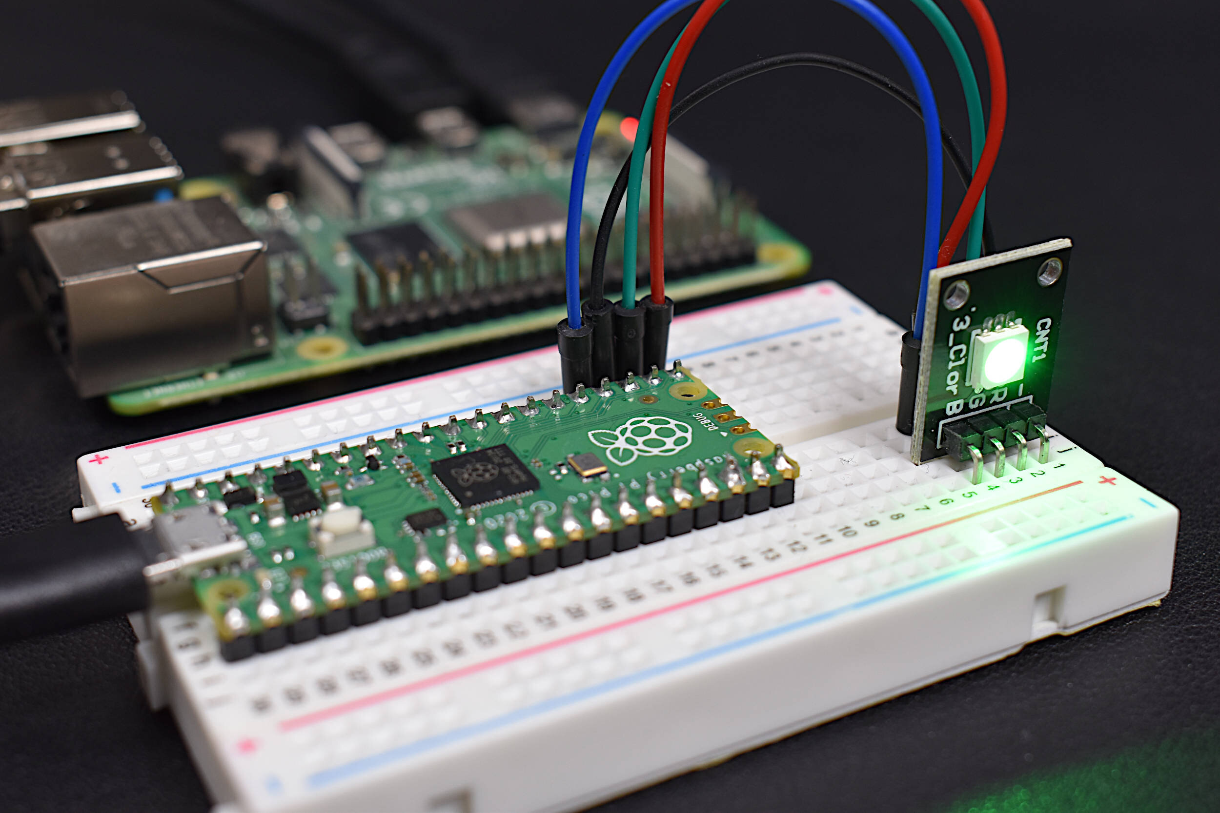
The Raspberry Pi Pico was recently released by the Raspberry Pi Foundation as a competitive microcontroller in the open-source electronics sphere. The Pico shares many of the capabilities of common Arduino boards including: analog-to-digital conversion (12-bit ADC), UART, SPI, I2C, PWM, among others. The board is just 21mm x 51mm in size, making it ideal for applications that require low-profile designs. One of the innovations of the Pico is the dual-core processor, which permits multiprocessing at clock rates up to 133 MHz. One particular draw of the Pico is its compatibility with MicroPython, which is chosen as the programming tool for this project. The focus on MicroPython, as opposed to C/C++, minimizes the confusion and time required to get started with the Pico. A Raspberry Pi 4 computer is ideal for interfacing with the Pico, which can be used to prepare, debug, and program the Pico. From start to finish - this tutorial helps users run their first custom MicroPython script on the Pico in just a few minutes. An RGB LED will be used to demonstrate general purpose input/output of the Pico microcontroller.
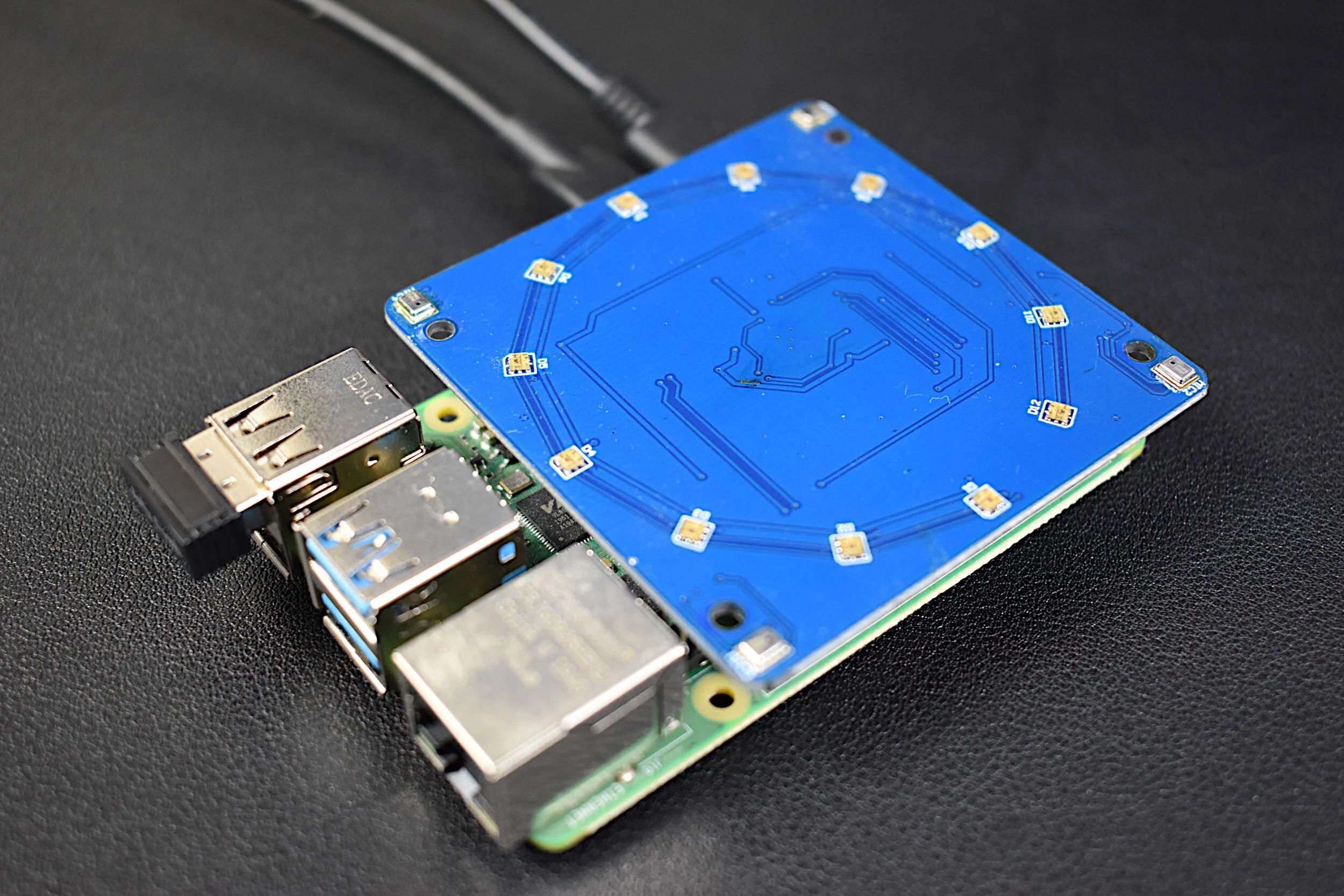
Read MoreThe QuadMic Array is a 4-microphone array based around the AC108 quad-channel analog-to-digital converter (ADC) with Inter-IC Sound (I2S) audio output capable of interfacing with the Raspberry Pi. The QuadMic can be used for applications in voice detection and recognition, acoustic localization, noise control, and other applications in audio and acoustic analysis. The QuadMic will be connected to the header of a Raspberry Pi 4 and used to record simultaneous audio data from all four microphones. Some signal processing routines will be developed as part of an acoustic analysis with the four microphones. Algorithms will be introduced that approximate acoustic source directivity, which can help with understanding and characterizing noise sources, room and spatial geometries, and other aspects of acoustic systems. Python is also used for the analysis. Additionally, visualizations will aid in the understanding of the measurements and subsequent analyses conducts in this tutorial.
Read MoreIn this tutorial, another method of control is introduced that involves manual control using input from the serial monitor. This means each pin can be turned on or off using the human input to the serial monitor. An RGB LED is used to demonstrate the capability of serial monitor control, where each color of the LED is controlled individually using dedicated Arduino pins.
Read MoreOptical fingerprint sensors take low-resolution snapshots of the tip of a finger and create arrays of identifiers that are then used to uniquely identify a given fingerprint. The AS608 is capable of storing up to 128 individual fingerprints. This tutorial will introduce the AS608 Arduino-compatible fingerprint sensor and how to validate and reject fingerprints based on the enrolled fingerprint information that will be given to the sensor. The fingerprint algorithm is handled by the AS608 and Arduino, so this tutorial will focus on implementation and putting the pieces together to make a working fingerprint sensor with Arduino.
Read MoreA demultiplexer will be used to control 8 LEDs using just 3 digital pins on the Arduino board. This method of demultiplexing frees up pins on the Arduino, but also makes control of multiple LEDs easier by consolidating the power given to each LED. This will allow us to use LEDs without resistors. In general, a demultiplexer uses N boolean outputs to control 2N switches. In our case, the CD4051 multiplexer will be used as a demultiplexer using 3 digital pins and boolean logic to control 8 individual LEDs. Several skills will also be developed, specifically with regard to programming in the Arduino programming language. Pulse-width modulation (or brightening and dimming) of LEDs will be explored, as well as randomization of LED blinks, along with the general selection process for boolean switching with the demultiplexer.
Read MoreThe use of LED based electronics has significantly increased in the past few years. They have proven to be more efficient and nearly 5 times cheaper than normal incandescent units. But with their use came one downside: heat. Some devices tend to use a number of LEDs that remain on for a long period of time and so can overheat. The LEDs are usually mounted on PCBs and can therefore cause significant damage. There is however one alternative to common PCBs i.e. metal core printed circuits (MCPCBs).
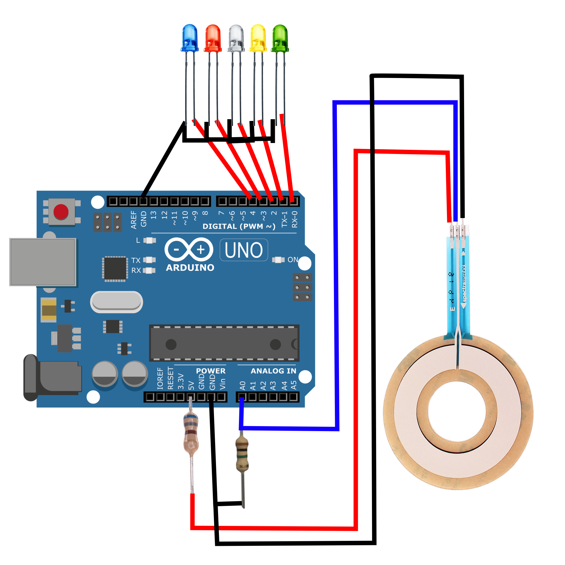
Read MoreHow to use a soft, circular-membrane potentiometer with an Arduino board. Potentiometers function by altering the voltage of a system by mechanically changing the resistance associated with a voltage divider. In a traditional potentiometer (think of turning a volume knob), we are physically changing the voltage of a system. In the case of a soft potentiometer (where the name SoftPot comes from), we are altering the resistance of the voltage divider by physically depressing the potentiometer, thereby changing the resistance at a contact point. The working principle is exactly the same, but in the SoftPot’s case, we are pressing, and for a knob we are rotating.
Read More


