Controlling Arduino Pins from the Serial Monitor
“As an Amazon Associates Program member, clicking on links may result in Maker Portal receiving a small commission that helps support future projects.”
Arduino control has been explored through various ways including Bluetooth control, programmatic control, and sensor control. In this tutorial, another method of control is introduced that involves manual control using input from the serial monitor. This means each pin can be turned on or off using the human input to the serial monitor. This makes control simple and versatile, which is necessary for some applications.
For Arduino boards, the serial monitor can act as a diagnostic and verification tool for sensors and scripts. The simplest use of the serial monitor is also a great way to verify that a given Arduino board is communicating properly with the computer it is connected with. Below I have given the simplest use of the serial monitor:
void setup() {
  Serial.begin(9600);
  Serial.println("Example Code");
}

void loop() {
}
By uploading the code above and opening the serial port, the monitor should read:
Example Code
This is the simplest use of the serial monitor. It doesn’t tell us much apart from an indication that the microcontroller is communicating serially with the computer.
We can look at a more involved example by reading from the serial port and printing out any inputs to the serial port. This is also shown in the code below:
void setup() {
  Serial.begin(9600);
}

void loop() {
  while (Serial.available()){
    Serial.println(Serial.read());
  }
}
An example output produced by the script above is given below. The serial port reads each input character individually and prints it out as an integer (this is why we see integers different from the numbers we input).
Next, we want to decode the inputs and print them out as ASCII characters, instead of integers. This will later allow us to control pins based on input characters. Below, the input can be decoded by first reading the input as a “char” and then printing that “char” variable just as above:
void setup() {
  Serial.begin(9600);
}

void loop() {
  while (Serial.available()){
    char in_char = Serial.read();
    Serial.println(in_char);
  }
}
Now we have the expected outputs based on our inputs. This simple method will be the basis for controlling our Arduino pins from the serial monitor.
Next, we need to use an ending character in order to notify the serial monitor that the input has ended. The end character is the ‘\n’ or newline end character. We also need to ENSURE that the dropdown window on the serial monitor is changed from ‘No line ending’ to ‘Newline.’ The code that decodes the input and prints it to the serial port is given below:
String in_chars = "";

void setup() {
  Serial.begin(9600);
}

void loop() {
  char in_char = ' ';
  while (Serial.available()){
    in_char = Serial.read();
    if (int(in_char)!=-1){
      in_chars+=in_char;
    }
  }
  if (in_char=='\n'){
    Serial.print("Text Entered: ");
    Serial.print(in_chars);
    in_chars = "";
  }
}
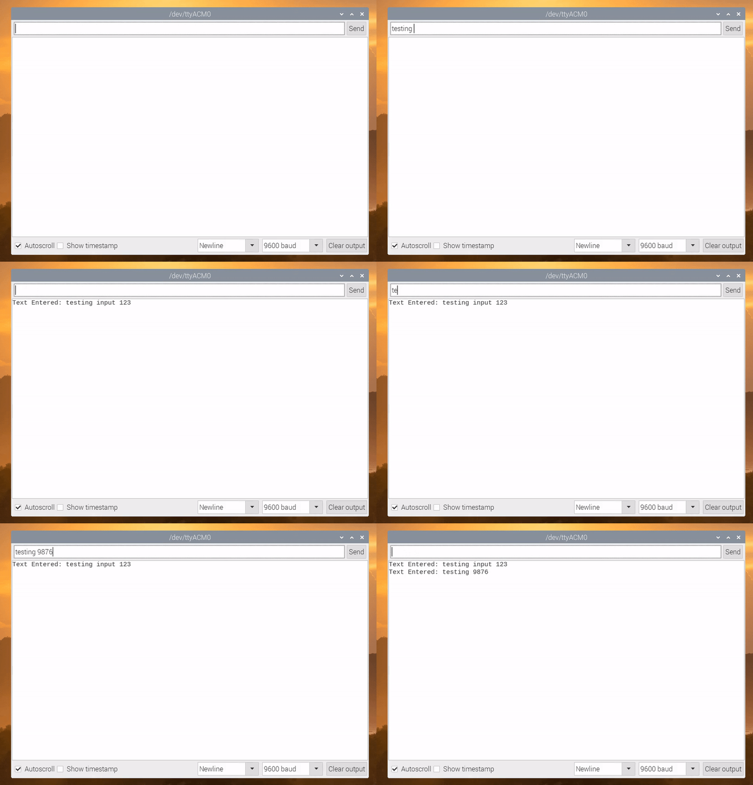
A printout example of the code above is also given below, demonstrating the script’s ability to decode full inputs to the serial monitor:
An RGB LED will be used to demonstrate the control capabilities of the serial input methods. An RGB LED is a good selection because it allows us to test three separate pins of the Arduino at the same time. The parts list for the subsequent demonstration is given below:
The code used to control the pins on the Arduino using the serial port is given below:
int int_array[18] = {0,0,0,0,0,0,0,0,0,0,0,0,0,0,0,0,0};
String pin_str = "";

void setup() {
  Serial.begin(9600);
  for (int ii = 2;ii<=sizeof(int_array)/sizeof(int_array[0]);ii++){
    pinMode(ii,OUTPUT);
  }
}

void loop() {
  while (Serial.available()){
    char in_char = Serial.read();
    if (int(in_char)!=-1){
      pin_str+=in_char;
    }
    if (in_char=='\n'){
      int pin_num = pin_str.toInt();
      int_array[pin_num] = !int_array[pin_num];
      digitalWrite(pin_num,int_array[pin_num]);
      Serial.print("Pin # ");
      Serial.print(pin_num);
      if (int_array[pin_num]==0){
        Serial.println(" OFF");
      } else {
        Serial.println(" ON");
      }
      pin_str = "";
    }
  }
}
The code permits boolean control of each of the pins on the Arduino from digital pins D0-D13, and even analog pins A0-A5. The RGB led can be wired to any of the pins on the Arduino (except the ground MUST be wired to the Arduino ground (GND) pin). Once each of the RGB pins is wired to an Arduino pin, open the serial port and type in the number that corresponds to the wired RGB pin and watch the LED light up!
Arduino is a powerful framework because it allows multiple ways of controlling devices. In this case, an RGB LED is controlled using just the serial port. I introduced the serial port communication by user input, and how to decode the inputs to read the appropriate input values in Arduino. From this, we were able to control the RGB LED using simple inputs to turn each red, blue, and green color individually. The routine was introduced as an alternate to other methods for controlling modules, apart from programmatic control or another method of control involving a wireless module. This method is simple, intuitive, and straightforward.
See More in Arduino and Sensors:


