An Introduction to RFID with Arduino
“As an Amazon Associates Program member, clicking on links may result in Maker Portal receiving a small commission that helps support future projects.”
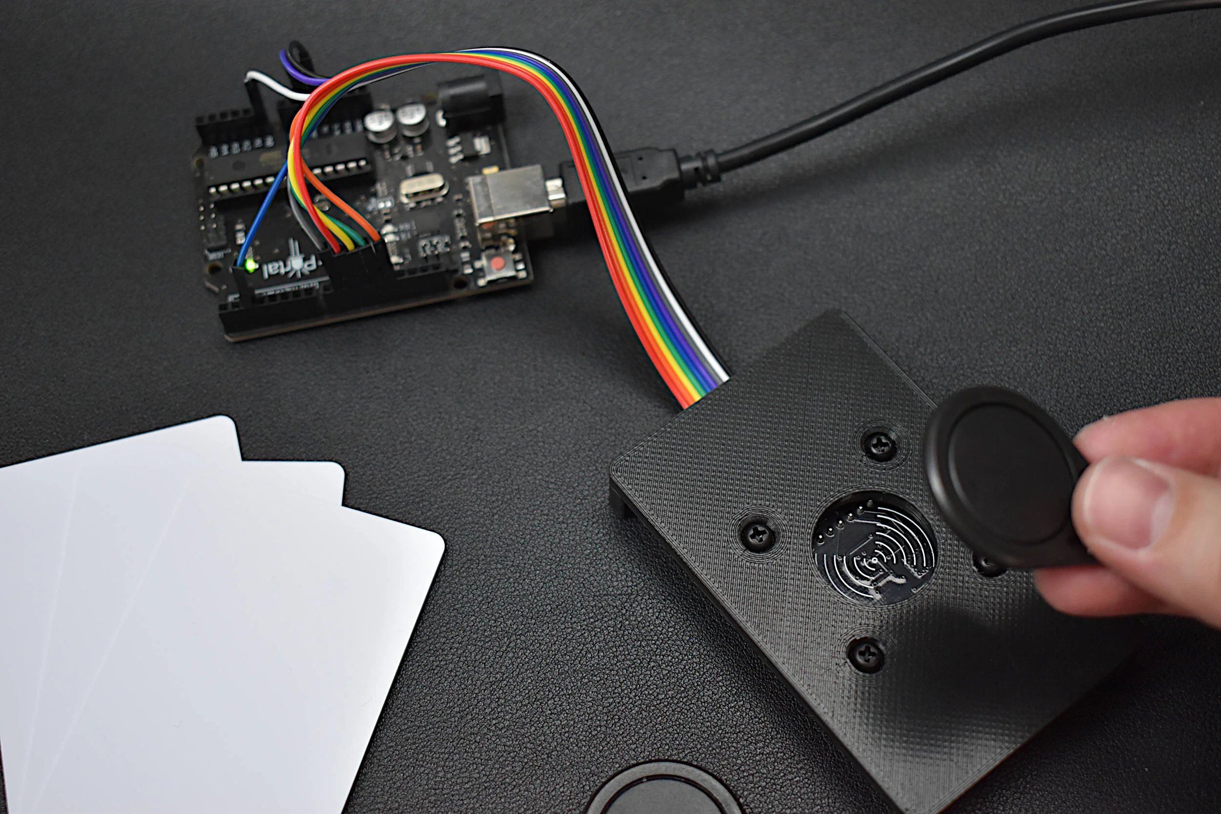
Radio Frequency Identification, or RFID, is a widely used technology developed for storing and retrieving information in radio frequency-enabled devices. Most often, RFID systems consist of one or multiple RF tags, an RF reader, and a database. The RFID tags have unique identifiers (UIDs) that allow for identification by the reader via the database. RFID tags can be active or passive, meaning they either require external power (active) or are powered by the reader upon scanning (passive). Passive RFID tags are most commonly used for building and security access, shipment tracking, and inventory monitoring; while active tags are used for road tolls and asset tracking in larger spaces across longer distances. The radio frequencies used in RFID can range from low frequency (124 kHz+) to ultra high frequency (900 MHz - 2.4 GHz), depending on the application [read more about the specifics of RFID here and here and here]. In this tutorial series, passive, high frequency (13.56 MHz) RFID tags are the focus, as they are very compact, inexpensive, and require no external battery power. Using an Arduino board, a common RFID reader (MFRC522), and a few RFID tags/cards, we will be exploring methods for reading and writing RFID information in an attempt to understand how RFID communication works and identify the limits of the technology with Arduino.
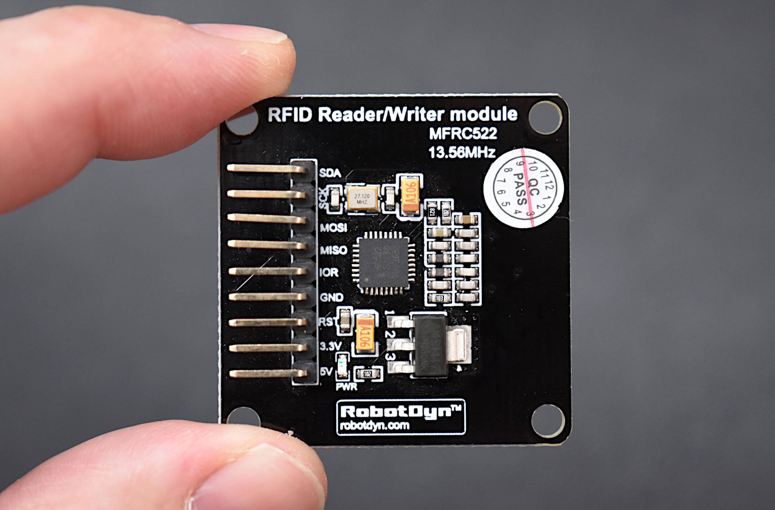
We will be using an Arduino Uno board and an MFRC52213.56 MHz RFID reader in this tutorial, along with several RFID tags and cards. The MFRC522 communicates with the Arduino board via SPI, so we will need quite a few jumper wires to connect the two devices. We’re also interfacing with a Raspberry Pi 4 computer. The full parts list is given below:

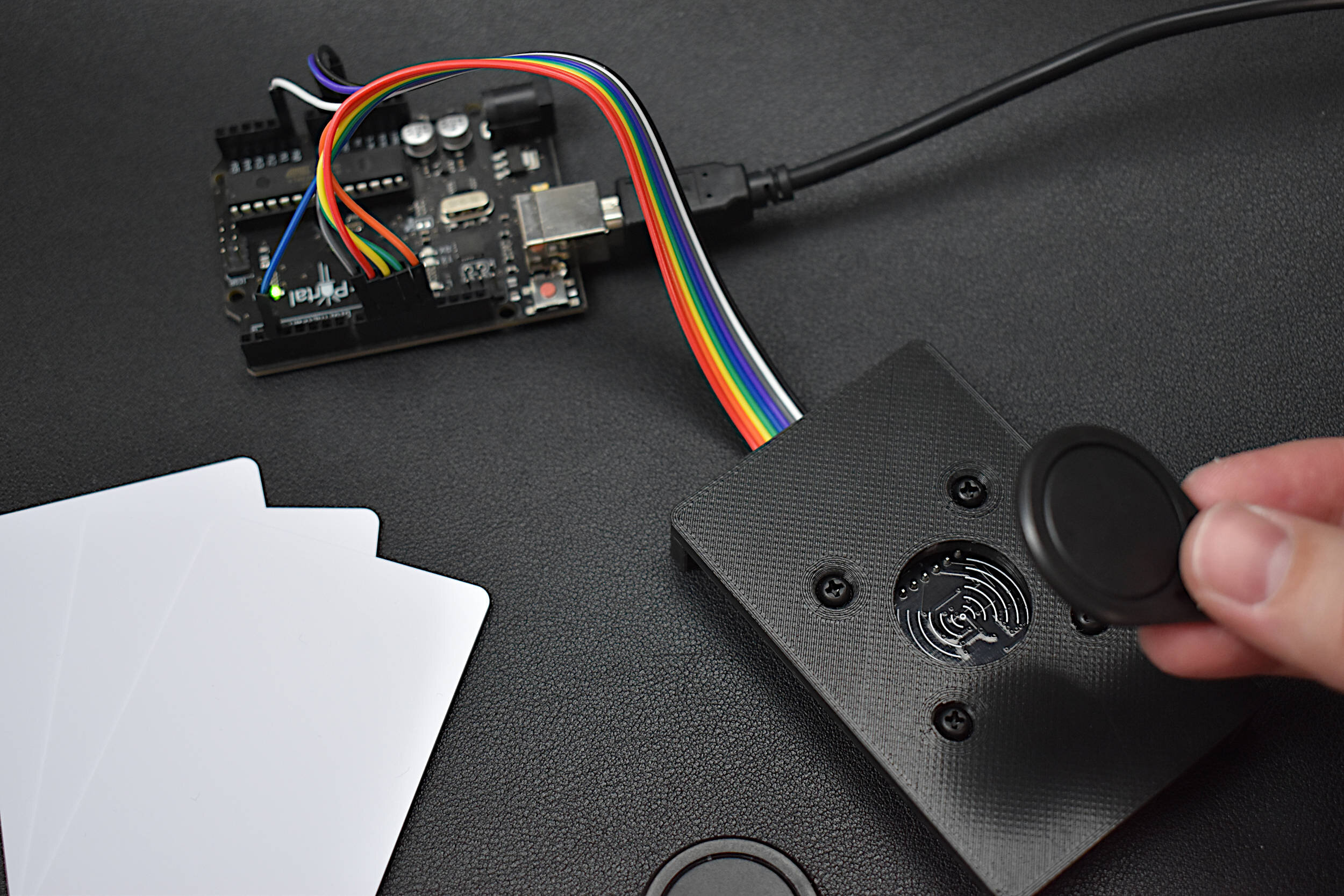
Radio Frequency Identification (RFID) is a common technology used for access control in schools and offices, animal identification, and product asset tracking. The MFRC522 module is a 13.56MHz RFID reader/writer that uses SPI to communicate with devices. The MFRC522 is compatible with both Arduino and Raspberry Pi, and a large range of RFID tags and cards. The kit we have assembled comes with an MFRC522 module, 6 RFID tags (3 fobs, 3 cards), and a 3D printed fixture for holding the MFRC522 - which makes getting started with RFID for Arduino very easy.
Included in the MFRC522 RFID Kit for Arduino:
1x MFRC522 RFID Module
6x RFID Tags (3x Cards, 3x Fobs)
1x 3D Printed Fixture
4x M3 Screws and Nuts for Affixing the MFRC522 Module to the Fixture
9x Female-to-Male Jumper Wires
Some Features of the MFRC522 RFID Module:
3.3V and 5.0V Supply Voltage
13.56MHz Operating Frequency
SPI Communication (Arduino, Raspberry Pi Compatible)
Capable of Communication with MIFARE Tags
10cm Read Range (between tag and reader)
Active Area: 30mm x 30mm
Module Dimensions: 36mm x 36mm x 7.5mm (accounting for pin headers)
MFRC522 Datasheet
See our tutorial on the MFRC522 with Arduino!
Some Features of the RFID Card:
Fully Read/Write Enabled
Can change their UID, and sectors
85.5mm x 54mm
13.56MHz Frequency Coils
MIFARE 1K Tags
Some Features of the RFID Fobs:
Read Enabled
Can write data, just not UID or manufacturer sectors
32mm x 40mm
13.56MHz Frequency Coils
MIFARE 1K Tags
The wiring between the MFRC522 and Arduino Uno board is given below for SPI connection:

The Arduino IDE’s Library Manager has a widely used RFID library that is compatible with the MFRC522 chip. The library, conveniently titled MFRC522, can be downloaded directly from the library manager and the user can get started right away with the many example scripts available to the Arduino platform. Below is a short sequence that outlines the procedure for downloading the MFRC522 library:
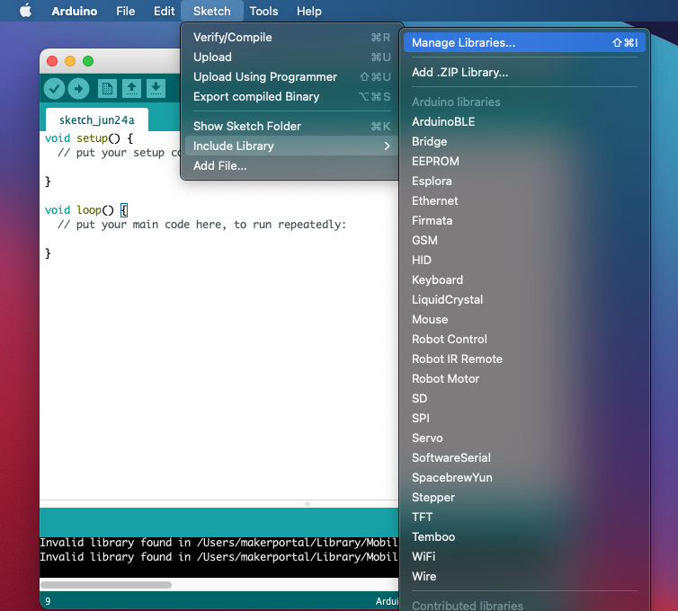
Navigate to the Library Manager
In the toolbar: Sketch -> Include Library -> Manage Libraries…

Search for the MFRC522 Library
Install the MFRC522 library developed by the GithubCommunity

Observe the Examples Available to the Selected Arduino Board (Uno in this case)
Navigate to File -> Examples -> MFRC522
We will be using these examples to read and write various information onto and from RFID cards with unique identifiers (UIDs).
Info Dump Test from RFID Tag:
The first checks we can do for verification of wiring, the Arduino library, and the validity of the RFID tags is to upload the “DumpInfo” code from the examples list. Upon uploading, assuming the wiring is correct and there are no errors, the user should place a tag within 4 inches of the MFRC522 scan area (the wave-like drawing on the MFRC522 board) and look for a print out on the Arduino serial port that looks similar to the following:

Info Dump from RFID Tag
Notice the terminology of sectors and blocks. These will be discussed below.
We can see from the info dumpy that the tag we are using is a MIFARE 1KB tag, which we can quantify by the multiplication of 64 blocks x 16 bytes per block = 1024 = 1KB. This is a standard classic MIFARE tag, which are used in low-security systems such as public transportation, schools and universities, and employee office access.
Below is a great MIFARE Classic Resource:
- "MIFARE Classic 1K-Mainstream contactless smart card IC for fast and easy solution development." Rev. 3.2 — 23 May 2018, by NXP.
In order to identify the terms printed above, we have compiled an explanation for each term based on the MIFARE document published by NXP:
- PICC - Proximity Integrated Circuit Card (Contactless Card). This is the tag/card being used as the ‘access device.’
-
UID - Unique Identifier. This is the 4-byte (32-bit) ID given to each PICC (tag). Over 4.2 Billion IDs are available with the 4-byte ID system. The UID is usually stored in Sector 0, block 0 in the first four bytes.
-
SAK - Select Acknowledge. This is used for compliance checking under international standards.
-
Sector - A sector is partitioned into 4-blocks. There are a total of 16 sectors in each 1K MIFARE tag.
-
Block - A block is comprised of 16-bytes of data.
-
Access Bits - These control the read/write permissions for each block.
There is also a detailed chart produced by NXP that explains many of the components printed by the Arduino code:

Courtesy of NXP, from MIFARE Classic EV1 1K
There are a few more pieces of information contained in the chart above that we can use to comprehend the output from the Arduino serial monitor. From our serial printout, the Key B for our tag sectors are FF FF FF FF FF FF, which is somewhat of a manufacturer default for classic MIFARE tags. Additionally, the NXP document goes into the details of the relationship between keys and access bits, however, we will not spend time on that as it can get quite complex. One final note on the info dump - we can identify crucial information about each card based on the zeroth block of the zeroth sector, known as the manufacturer data. In our card printed above, we can see that the first four bytes of block 0 contains the UID of the card.
Using the table provided by NXP and the definitions above, we can identify a few key parameters for our specific tag (from the Arduino printout above):
UID - CE 5B F4 3C
SAK - 08
Key B - FF FF FF FF FF FF
In the next section, we will explore a few routines for altering these default values and seeing just how far we can push the customization of these RFID tags using the MFRC522 module.
We are going to attempt to change the Unique Identifier (UID) of each tag being placed in front of the MFRC522 active area. The MFRC522 example code ‘ChangeUID’ allows us to do this by giving the user the power to change the UID to a custom 4-byte address. We’re going to change the address of the tag printed out in the previous section, to a completely random address of “F3 45 1B 0C” for testing. If we place the same tag in front of the MFRC522 scan area, we get the following output, which we can compare with the previous output:

Previous tag scan output with factory defaults
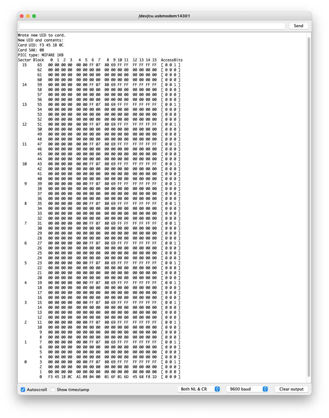
Tag scan after changing the UID with MFRC522
We can see that the only information that changed was the first five bytes of the zeroth block of sector 0. The first four bytes have been changed to the desired UID, while the fifth byte appears to be either random or specified by the write action (we have not identified this byte designation in the library).
Note: Only writable tags can have their UIDs changed. The white cards we are using are writable, and thus can have their UIDs changed. The black tags are read-only, and will not allow UID changes (Arduino will notify the user of this).
We tried several times to write new UIDs to our black tags, but we were unable. This was expected, due to the specification of read-only, however, we figured an attempt wouldn’t hurt!
Writing Data to RFID Tags
Next, we’ll attempt to write specific data to each tag to see what information we can store. Each sector (except sector 0) has three available blocks for storing data (4-blocks per sector, minus 1 for keying). Thus, we can store up to 48 bytes of data in each sector. This can leads to the storing of names, dates, location information, product information - the possibilities are expansive. We can start with the example in the Arduino MFRC522 library called ‘rfid_write_personal_data’ which will ask the user to input a first and last name for storing in the Electrically Erasable Programmable Read-Only Memory (EERPROM), also known as the 16-sectors of data.
Upon opening the serial monitor after uploading ‘rfid_write_personal_data’ the user should place their RFID tag in front of the MFRC522 active area. The serial monitor will ask for two inputs:
Type Family name, ending with #
Type First name, ending with #
The user must input a name followed by the # symbol. For example:
Smith#
John#
The resulting inputs will be saved in memory and should output the following if successful:

Successful Saving of First and Last Name to RFID Tag
In our case, we inputted Smith# and John#, which should output John Smith as the first and last name.
If we now upload the ‘rfid_read_personal_data’ we can see how the personal data is returned to us based on our inputs above:
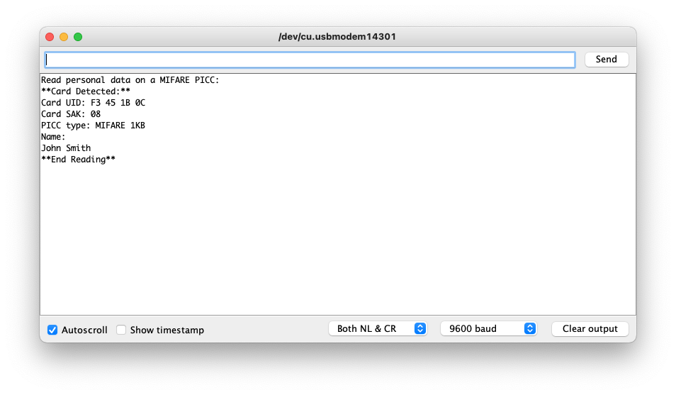
And this verifies that our data is saved to the RFID tag. We can see how the data is saved by again returning to the “DumpInfo” example and looking at the output:

Output of all 16 Sectors after saving first and last name
We can see that blocks 1,2 and 4,5 have changed, which is where the example code saved the personal data.
If we were to copy sector 1 and convert it from hex to UTF-8 characters, we get the following output:

The same can be done for the first name as well (contained in sectors 4), though sector four contains carriage return and newline characters as the first two bytes. These two characters are due to the setting on our serial monitor (Both NL & CR). If we change the line setting to "No line ending” this disappears and we just get “John” and “Smith” as outputs for sectors 1 and 4. Users can also verify the hex to UTF-8 values by inserting the hex output to a hex conversion website (such as: https://www.rapidtables.com/convert/number/hex-to-ascii.html).
RFID Resources:
- Want, Roy. "An introduction to RFID technology." IEEE pervasive computing 5.1 (2006): 25-33.
In this first entry of the RFID tutorial series with Arduino, the wiring, testing, and simple customization of RFID tags was introduced with the MFRC522 RFID module. The MFRC522 is read and controlled via SPI using an Arduino Uno board, which has a dedicated Arduino library downloadable from the library manager. Several of the available examples were used to introduce and explore the basics of RFID with Arduino and understand some of the inner workings of the library and radio frequency identification as a technology. RFID terms such as sectors, blocks, and unique identifiers were discussed and used to understand some of the examples provided by the Arduino RFID library. Four different examples were used to test the various capabilities of the MFRC522 module, which involve changing the UID of writable RFID tags, dumping the information contained on all sectors of a tag, and writing/reading custom data from an RFID tag. This tutorial will be continued in upcoming tutorials, which further delve into customization of the data contained in an RFID tag.
See more in Arduino: