Arduino SoftPot LED Meter (Membrane Potentiometer)
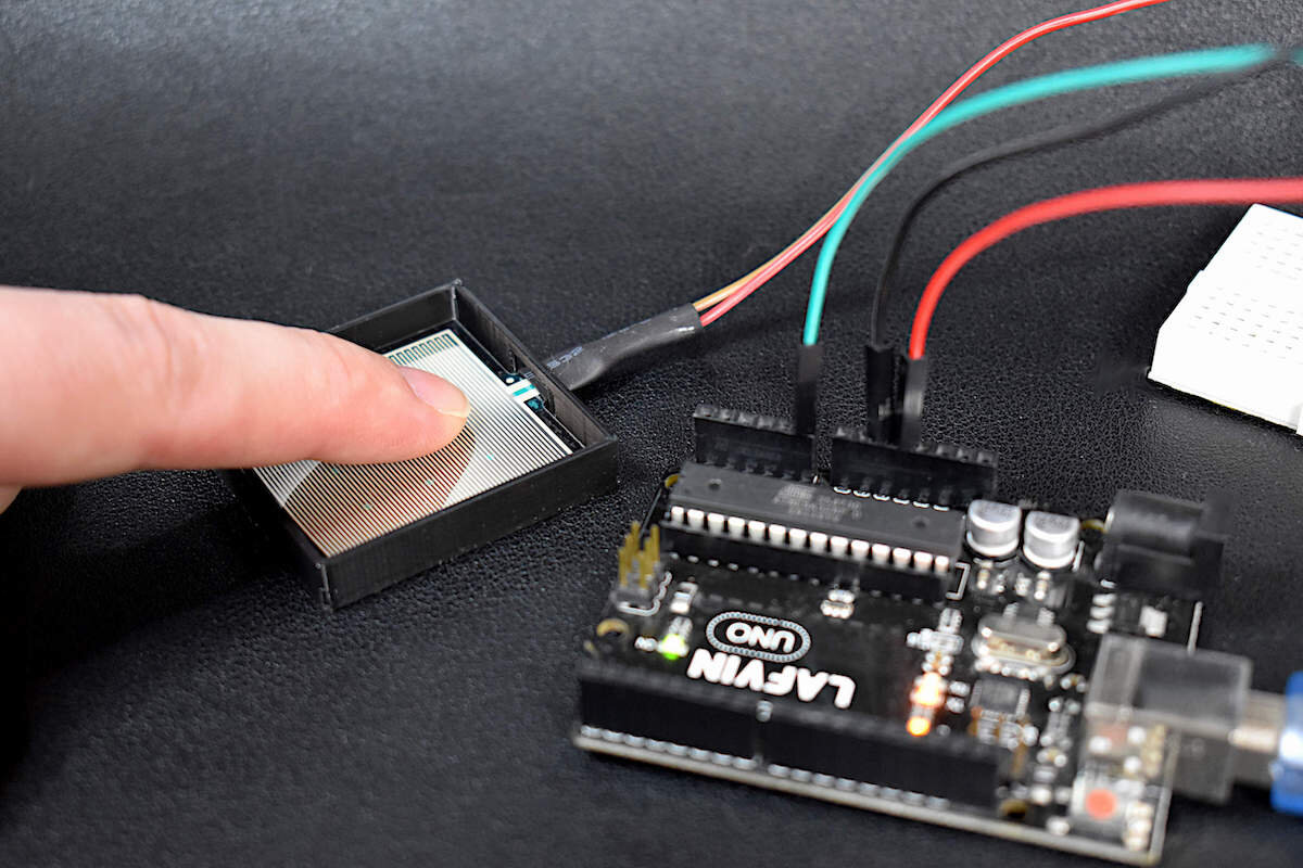
In this tutorial, I will demonstrate how to use a soft, circular-membrane potentiometer with an Arduino board. Potentiometers function by altering the voltage of a system by mechanically changing the resistance associated with a voltage divider. In a traditional potentiometer (think of turning a volume knob), we are physically changing the voltage of a system. In the case of a soft potentiometer (where the name SoftPot comes from), we are altering the resistance of the voltage divider by physically depressing the potentiometer, thereby changing the resistance at a contact point. The working principle is exactly the same, but in the SoftPot’s case, we are pressing, and for a knob we are rotating.
How the SoftPot Works
The SoftPot uses touch to connect the internal resistance to the data pin within the potentiometer. Therefore, if we are not touching the SoftPot, we have a reading of 0 V (assuming there is also a pull-down resistor to stabilize the signal). The figure below shows the inner workings (simplified) of the potentiometer. We can think of it as a varying resistance connected in a voltage divider. If we have no contact with the SoftPot, we get close to 0 V running through the data pin:

And if we touch the SoftPot at some point along the circular membrane, we create a connection between the data pin, the internal resistance of the membrane, and the voltage pin. Depending on the touch location, the resistance of the membrane will change, therefore resulting in a change in voltage (in the case of Arduino, from 0V - 5V). A touch can be visually modeled as shown below:

The SoftPot has a linear resistance response based on touch location, meaning that as we move along the circular path, we expect a linear voltage increase based on the touch location. This means that we could rev-up a motor or open a valve linearly based on the touch location. And in our particular case, we can divide the touch location into the amount of LEDs we are using, and get each LED to light up based on its particular fraction along the path of the circular membrane. If any of this is unclear, I will demonstrate later in this tutorial.
Parts List and Wiring
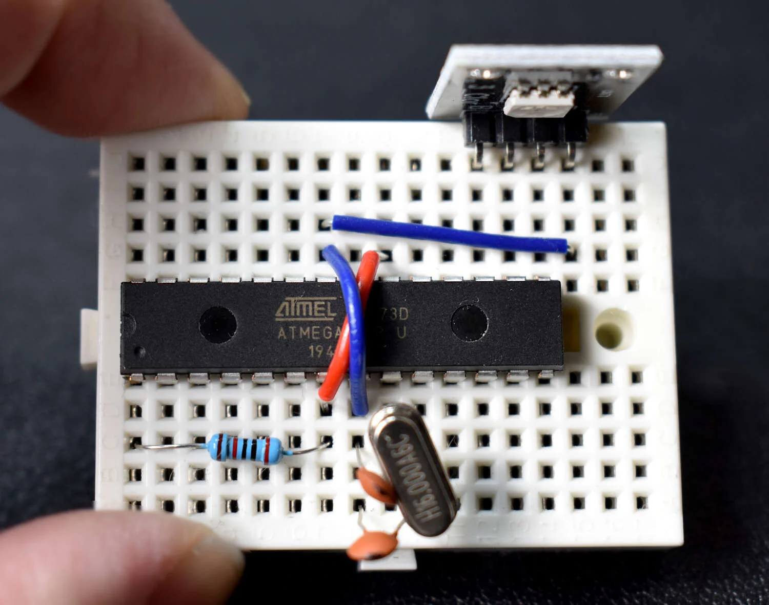
The parts used in this tutorial are shown below:
The wiring is incredibly important because of the sensitivity of the SoftPot. If the SoftPot experiences too much current, it will burn up and overheat, making the potentiometer useless. Therefore, I recommend using a several-hundred valued resistor on either end of the power/ground wiring, and a pull-down resistor to handle the data pin. The pull-down resistor will allow the user to set the untouched value to zero, and the maximum value to nearly 1023 (for the 10-bit Arduino).
CAUTION: BE CERTAIN THAT THE WIRING IS CORRECT PRIOR TO POWERING THE CIRCUIT, AS THE SOFTPOT CAN BE DAMAGED IF TOO MUCH CURRENT RUNS THROUGH THE PINS

I also elected to use 5 LEDs in my case, but up to 19 LEDs can be used (assuming the SoftPot is switched to pin A5). The easiest and most robust solution is to keep the SoftPot on A0 and use 14 LEDs from D0 - D13.
Also note: the middle pin on the SoftPot is the data pin.
Arduino Code
The Arduino code below uses the number of LEDs inputted by the user to create a visual meter showing how much voltage is being transmitted through the SoftPot. In other words, as the user presses along the SoftPot, the LEDs will light up in succession, and turn off in succession as the user lets go of the SoftPot. This can also be used to power other devices like fans, simply based on the point of depression on the SoftPot.
// Code for reading analog data from a SoftPot potentiometer
// with multiple LEDs

int sensorPin = A0; // analog pin where SoftPot is connected
float potval = 0.0;  // potentiometer x/1023.0 (10-bit)
int n_leds = 5; // number of LEDs (digital pins as outputs)

void setup() {

  for (int ii=0;ii<n_leds;ii++){
    pinMode(ii,OUTPUT);
  }

}

void loop() {
  // read the analog signal and get a value from 0 -> 1
  potval = analogRead(sensorPin)/1023.0;

  // make sure the LED doesn't flicker:
  if (int(3*n_leds*potval)==0){

  } else {
    // loop through the LEDs and only turn them on based on
    // the total number of LEDs and where the SoftPot is pressed
    for (int ii=0; ii<=int(n_leds*potval); ii++){
      digitalWrite(ii,HIGH);
    }
  }
  // turn off all other LEDs based on SoftPot pressing
  for (int jj=int(n_leds*potval); jj<14; jj++){
    digitalWrite(jj,LOW);
  }

}
Conclusion

In this tutorial, I demonstrated how potentiometers work and how to apply their linear response to a set of LEDs. The SoftPot, or soft potentiometer, demonstrated that the change in resistance of a voltage divider changes the voltage output of the SoftPot’s data pin. We can read the corresponding voltage using one of the Arduino’s analog pins. From there, we used a series of LEDs (5 in my case) to represent the voltage change visually through a light meter (or real-time LED meter). This gives us a visual representation of where the SoftPot is being pressed at any given time. Potentiometers are used in everyday consumer electronics from volume and tone knobs on guitars to heating and air-conditioning rheostats. The use of a SoftPot is a modern adaptation of a simple concept used everyday.
See More in Arduino and Engineering: