Arduino Tachometer - Using a Hall Effect Sensor (A3144) to Measure Rotations from a Fan
In engineering, a tachometer is a useful tool for calculating the rotational motion of a part. Tachometers read out revolutions per minute (RPM), which tells the user how often a rotating part completes one full rotation. RPM readings are used in the automotive, aerospace, and manufacturing fields [source]. Tachometers are important for determining relationships between fuel consumption and motor speed, safety of moving parts, and even wind speed indicators. Some tachometers are laser-based, but they can be material and color-dependent and even inaccurate under specific lighting conditions. In this experiment and tutorial, I will demonstrate how to build an inexpensive,reliable hall effect tachometer that attaches a neodymium magnet to a rotating shaft of a DC fan. The speed of fans is important because they are proportional to the amount of cooling supplied to a system, and without an accurate depiction of fan speed - cooling systems can malfunction, resulting in large loss of mechanical and industrial equipment.
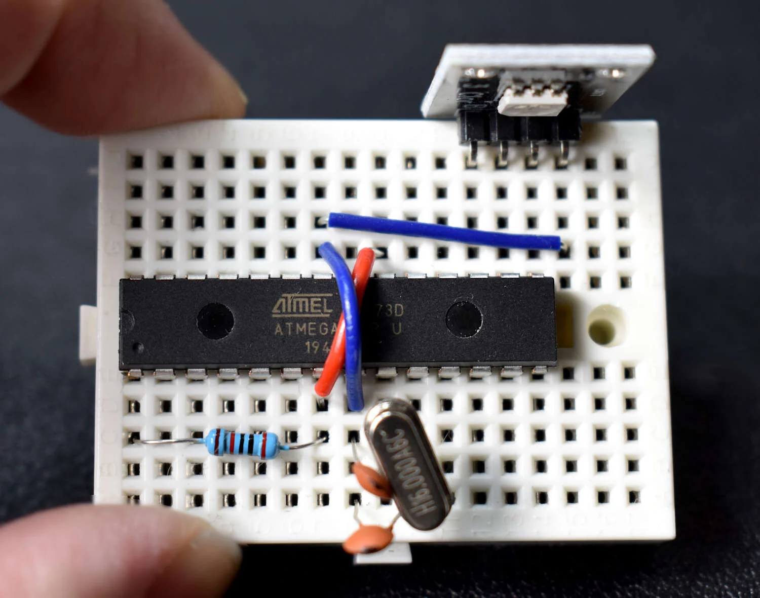
Experiment Parts List
The parts needed for this experiment are somewhat open-ended, but I will list the parts that I used for my specific experiment. Any fan or motor can be used, as long as a magnet can be attached to it safely and the hall sensor is able to get close enough to the spinning shaft. The parts I used are:

The Hall Effect and A3144
The hall effect, in short, is a relationship between electric and magnetic fields through a semiconductor that allows electricity to flow when a magnetic field is applied within the vicinity of a given hall sensor. In our case, we will be using the A3144 hall effect sensor, which is a unipolar sensor. Unipolar sensors are great for scenarios where only one pole of magnet is needed. This allows us to stick a magnet to a moving object and as it cycles through its rotation, each time it passes the hall sensor, the hall sensor registers its passing and we can say that one period has been completed.
The A3144 pinout is shown below:
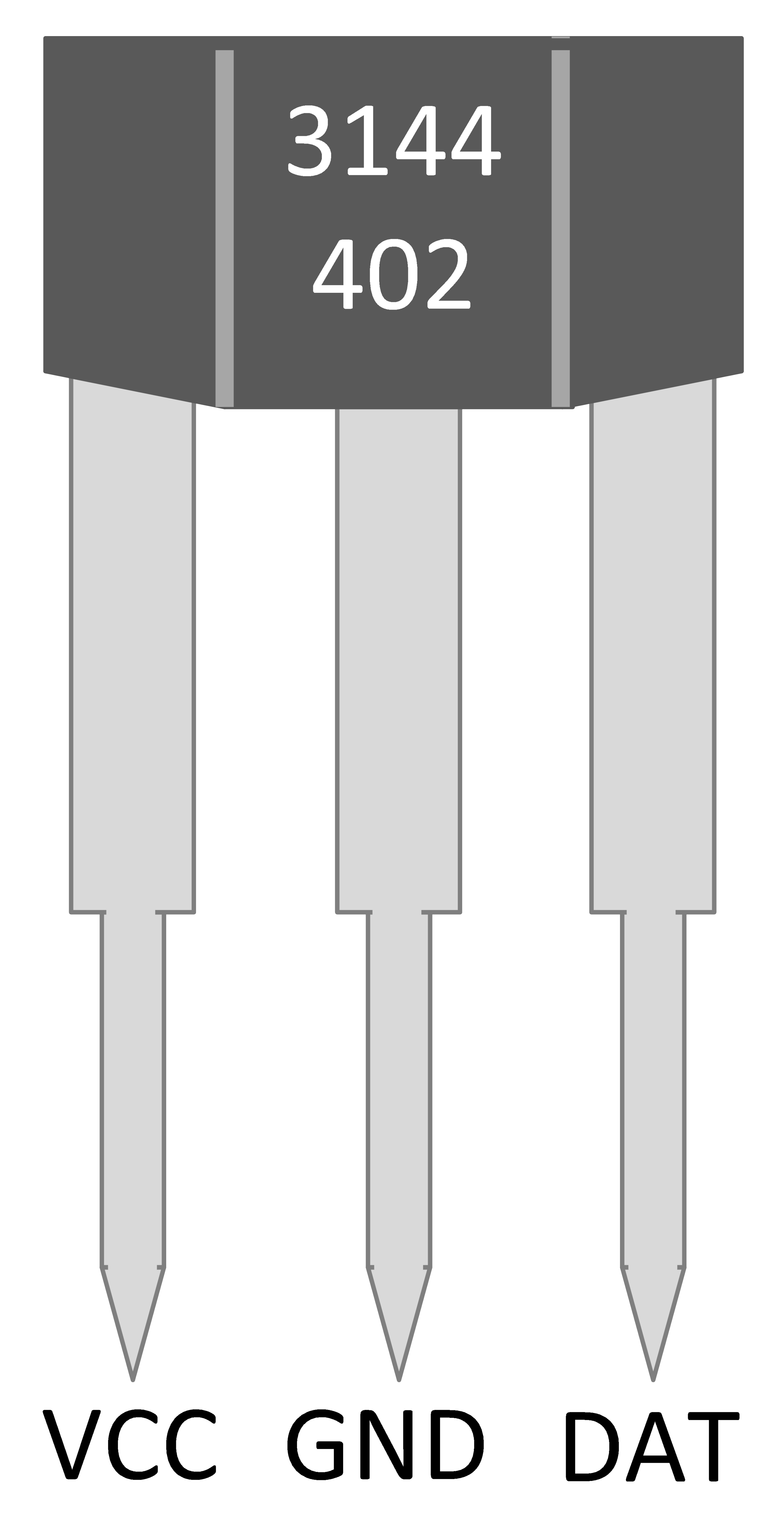
A3144 Unipolar Hall Effect Sensor. When a magnet is brought near the sensor head, the DAT pin registers the magnetic field.
The way we will be using the A3144 is by using a pullup resistor, which means that we add a resistor between VCC and DAT to keep the value of the data pin at maximum when no magnet is near. This is shown below:

Conversely, when we put the magnet within range of the hall sensor, we get a LOW value. This is also shown below:

The cycle between low and high shown above is what’s expected when we attach a magnet to a rotating part that will bring the magnet within and out of reach of the hall sensor. The cycling will be handled in the coding section of this tutorial, but we need to wire the hall sensor to the Arduino and prepare our setup for the tachometer experiment.
Arduino Setup and Wiring
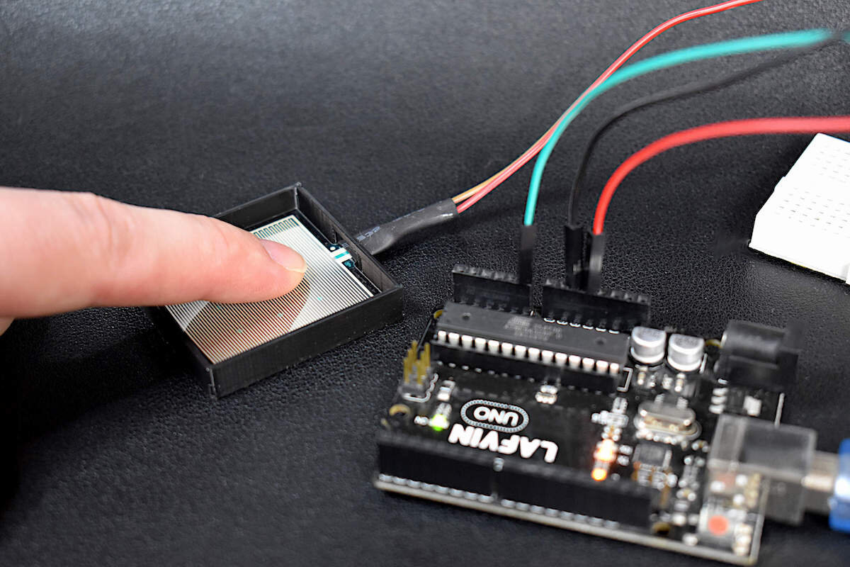
This experiment requires very specific attention to the proximity between the neodymium magnet and the hall sensor (A3144). If the hall sensor and magnet are just far enough, the hall sensor will periodically register events and produce meaningless results. In this particular case, the closer the two parts - the better. We also must ensure that the fan or circulating device is not impeded by the presence of the hall sensor or the magnet. This is why I have chosen tiny magnets to adhere to the fan.
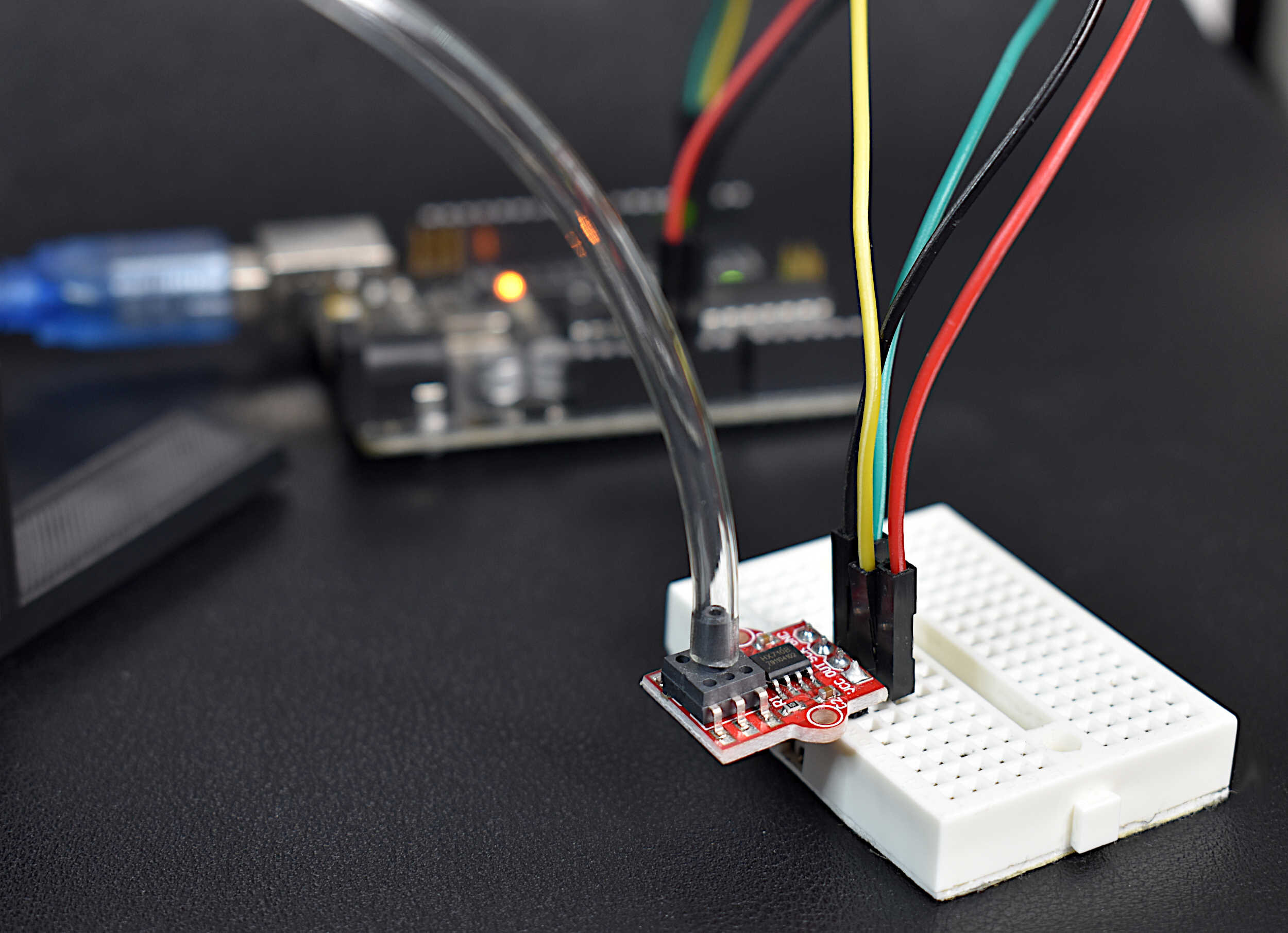
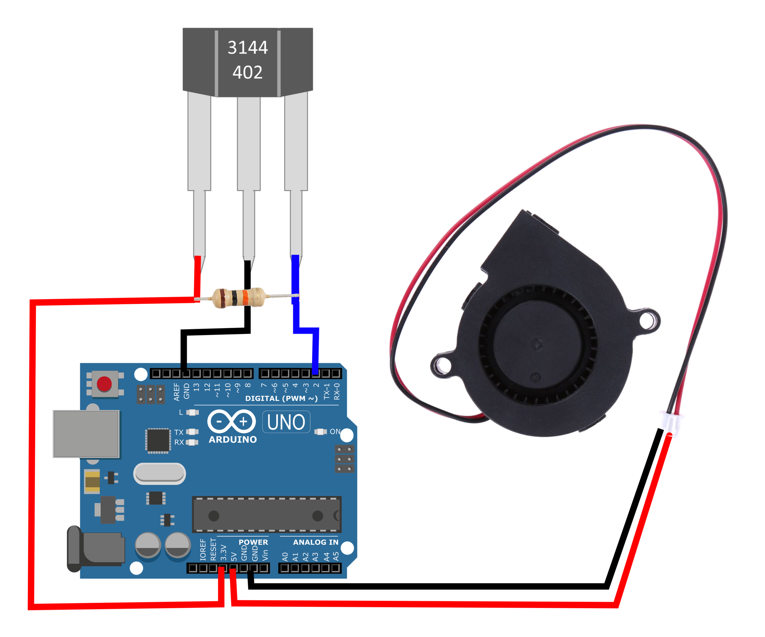
Below is the wiring diagram for the A3144 Hall sensor and the blower to the Arduino Uno board:
The most important thing to keep in mind when setting this experiment up is the proximity between magnet and hall sensor. Below is my setup that shows the attached magnet to the rotating fan and just how close the hall sensor and magnet are:
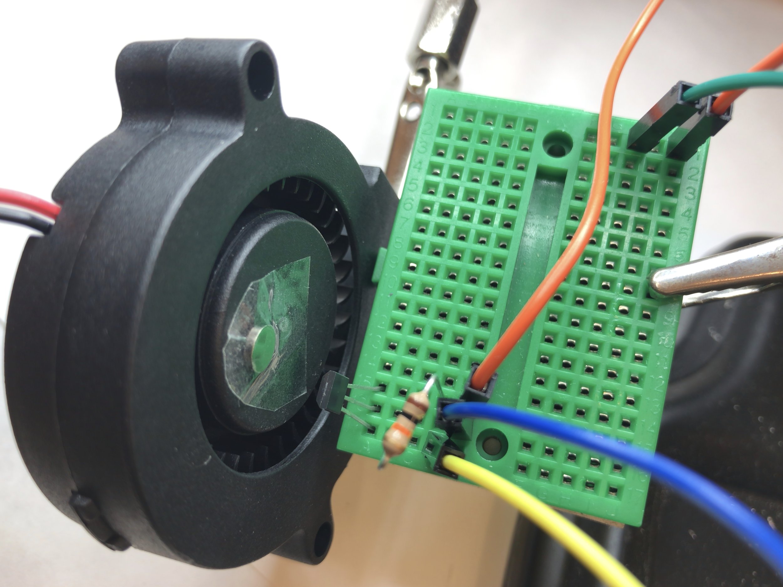
I recommend testing the hall sensor and magnet setup before the fan is moving. This will give a better idea of whether the magnet is close enough to the sensor and tripping it correctly. This is also why I’m using Neodymium magnets - as they produce large magnetic fields over long distances, despite their small volume.
Arduino Code
As discussed in previous sections, we expect the hall pin to be high most of the time, and low when the magnet crosses in front of the sensor. Therefore, we must code the Arduino to trip and add a period in when the hall pin reads zero. Below is the Arduino code that handles the counting of the tachometer and how it also handles the difficulty of continuous trips.
// digital pin 2 is the hall pin
int hall_pin = 2;
// set number of hall trips for RPM reading (higher improves accuracy)
float hall_thresh = 100.0;

void setup() {
  // initialize serial communication at 9600 bits per second:
  Serial.begin(115200);
  // make the hall pin an input:
  pinMode(hall_pin, INPUT);
}

// the loop routine runs over and over again forever:
void loop() {
  // preallocate values for tach
  float hall_count = 1.0;
  float start = micros();
  bool on_state = false;
  // counting number of times the hall sensor is tripped
  // but without double counting during the same trip
  while(true){
    if (digitalRead(hall_pin)==0){
      if (on_state==false){
        on_state = true;
        hall_count+=1.0;
      }
    } else{
      on_state = false;
    }

    if (hall_count>=hall_thresh){
      break;
    }
  }

  // print information about Time and RPM
  float end_time = micros();
  float time_passed = ((end_time-start)/1000000.0);
  Serial.print("Time Passed: ");
  Serial.print(time_passed);
  Serial.println("s");
  float rpm_val = (hall_count/time_passed)*60.0;
  Serial.print(rpm_val);
  Serial.println(" RPM");
  delay(1);        // delay in between reads for stability
}
Conclusion
In this tutorial I introduced the hall effect sensor and its relevance to engineering. During the tutorial, the user learned about the behavior of a unipolar hall sensor (A3144) and how it can function as a tachometer. I demonstrated a simple experiment using a 5V blower fan, hall sensor, and neodymium magnet attached to the fan. The setup allowed us to print out values for the approximate RPM of the fan, which can give us a more accurate idea of the flow rate of the fan. Tachometers are very useful for measuring speeds of various parts in mechanical systems like aircraft and automobiles. This method of tachometer: a contactless, interference resistant (unlike laser tachometers), and simple setup allows engineers to investigate rotational motion of a fast-moving part by coding and wiring with inexpensive equipment using Arduino.
See More in Engineering and Arduino: