DIY Arduino Board
The Arduino platform was originally created as a way to reduce the cost of microcontrollers in educational settings, while simultaneously making electronics and programming more approachable for users with less technical experience (read more about the true history of Arduino here). An Arduino board is simply a collection of electronic components that enable users to rapidly prototype electronics ideas without the need for high level electronics assembly. The classic Arduino Uno has an ATmega328P as its microcontroller, along with LEDs, regulators, and fixtures that make it easy to get started with the Arduino platform. A DIY Arduino board is presented here, with most of the capabilities of the classic Arduino Uno board, but with a slimmer profile and more flexibility in hardware. The advantage to using the DIY Arduino board is its ability to change the input voltage (2.7V - 5.5V), the crystal oscillator (0-16MHz), and the use of LEDs and regulators when needed.
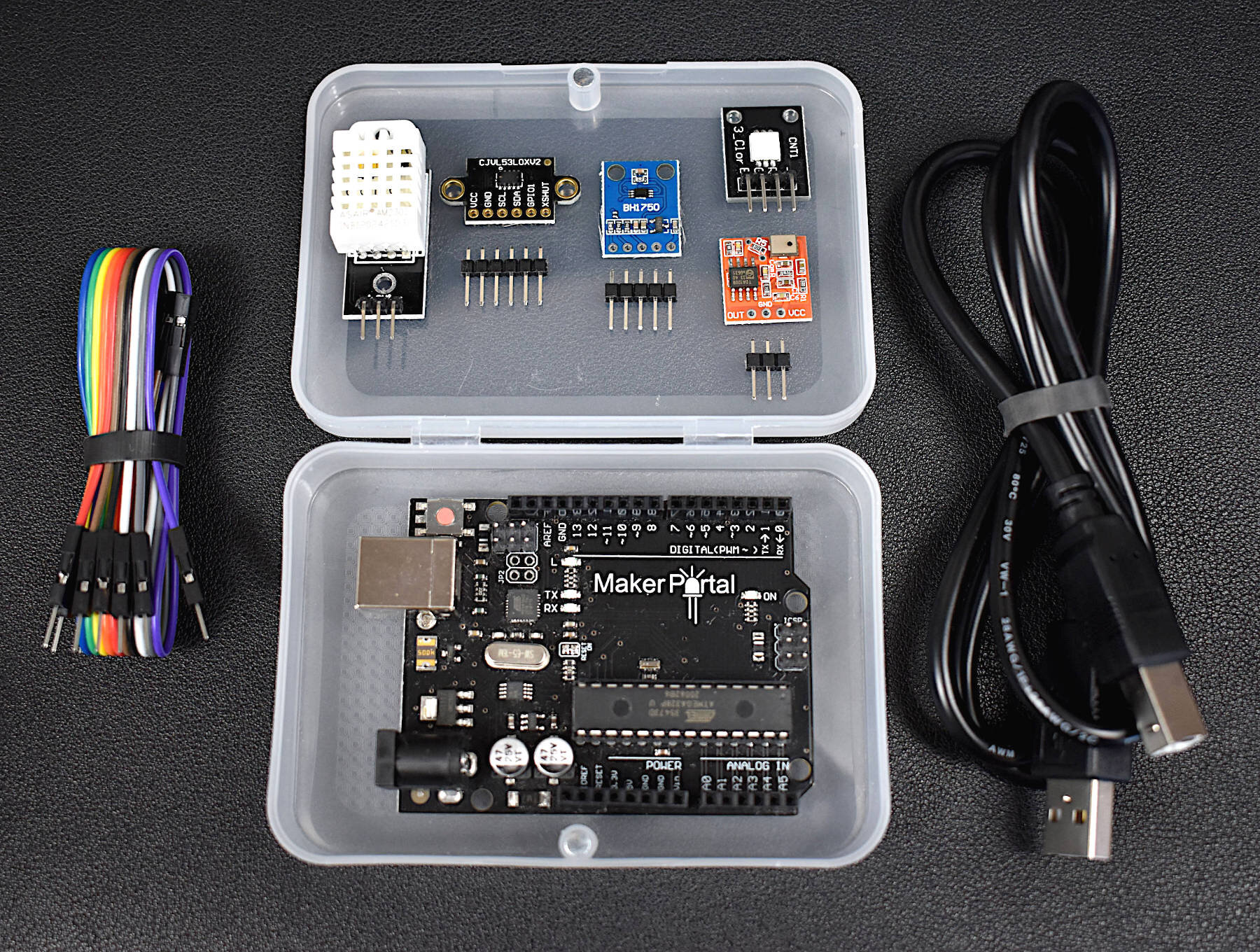
The DIY Arduino board can be assembled using a series of components that are easily found and likely already available in a maker’s toolbox or engineer’s work space. Maker Portal has put together the components into a kit, which can be found on our site.
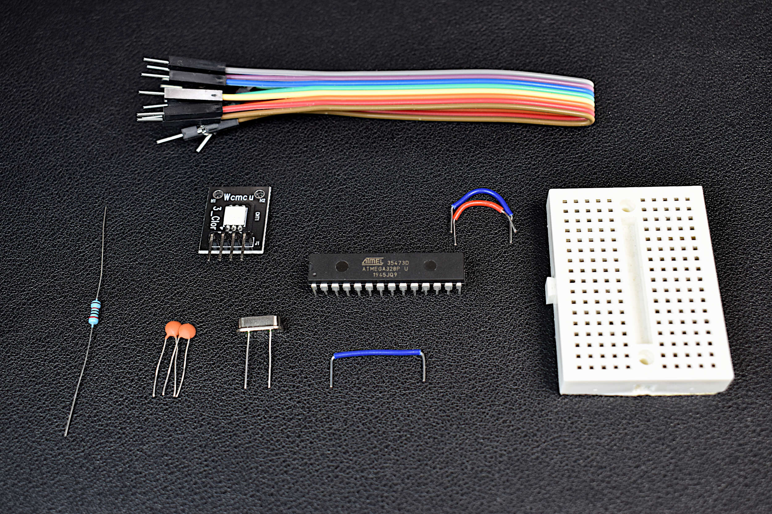
Included in the DIY Arduino Kit + Uno Board:
1x ATmega328P-U Microcontroller
1x 16MHz Quartz Crystal Oscillator
2x 22pf Capacitors
1x 20kOhm Resistor
1x RGB LED
1x Mini Breadboard
10x Jumper Wires
Arduino Uno Rev3 Board
The DIY Arduino Kit + Uno Board includes everything the user needs to follow along with this tutorial. In this tutorial specifically, an Arduino Uno Rev3 board (with a removable ATmega328P) will be used as the USB to TTL adapter, however, any other adapter can be used. The expectation is that the user either already has one of these, or purchases the DIY kit with the Uno Board. If the user already has an Uno Rev3 board at home, then the components in the DIY Arduino Kit without the Uno board suffices (and is only $8 from our store).
An Arduino board is a collection of electronic components that enable users to rapidly prototype with a central microcontroller. LEDs, regulators, and fixtures make getting started with the Arduino platform simple. This DIY Arduino kit aims to demystify the Arduino board by taking the essential components of an Arduino board and putting them into one kit. The DIY Arduino kit uses an ATmega328P-U as the central microcontroller, and some essential electronic components necessary to function as an Arduino board.
Included in the DIY Arduino Kit:
1x ATmega328P-U Microcontroller
1x 16MHz Quartz Crystal Oscillator
2x 22pf Capacitors
1x 20kOhm Resistor
1x RGB LED
1x Mini Breadboard
10x Jumper Wires
Included in the DIY Arduino Kit + Uno Board:
Everything Above + Arduino Uno Rev3 Board for Programming the DIY Board
Some Features of the DIY Arduino Kit:
Fully-Functional Arduino Board
Low Power Consumption due to lack of LEDs or Regulators
Arduino Already Bootloaded onto the ATmega328P
Low Profile Breadboard, smaller than an Arduino Uno board
RGB LED for testing code
2.7V - 5.5V Operating Range
5µA Low Current when Powered Down (3.3V, 16MHz)
8mA Working Current (3.3V, 16MHz)
Jumper Wires for Uploading Code, and Interacting with Sensors and Motors
Some Features of the ATmega328P-U Chip:
28-Pins in a Dual In-Line Packaging (2x14 pins)
Capabilities: SPI, I2C, USART, PWM
2.7V - 5.5V Input Voltage Range
1µA - 1.5mA Power Consumption (3V, 4MHz)
10-bit Analog-to-Digital Converter (8-channels)
Interrupt Capabilities (2-channel)
32KB of Flash Memory for Programming
0MHz-16MHz Frequency Capabilities (External Crystals)
8-bit/16-bit Timers
Compatible with Arduino IDE
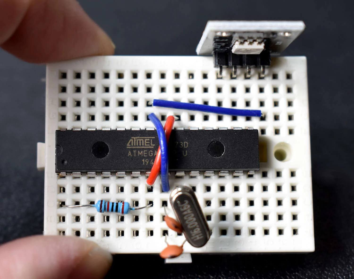
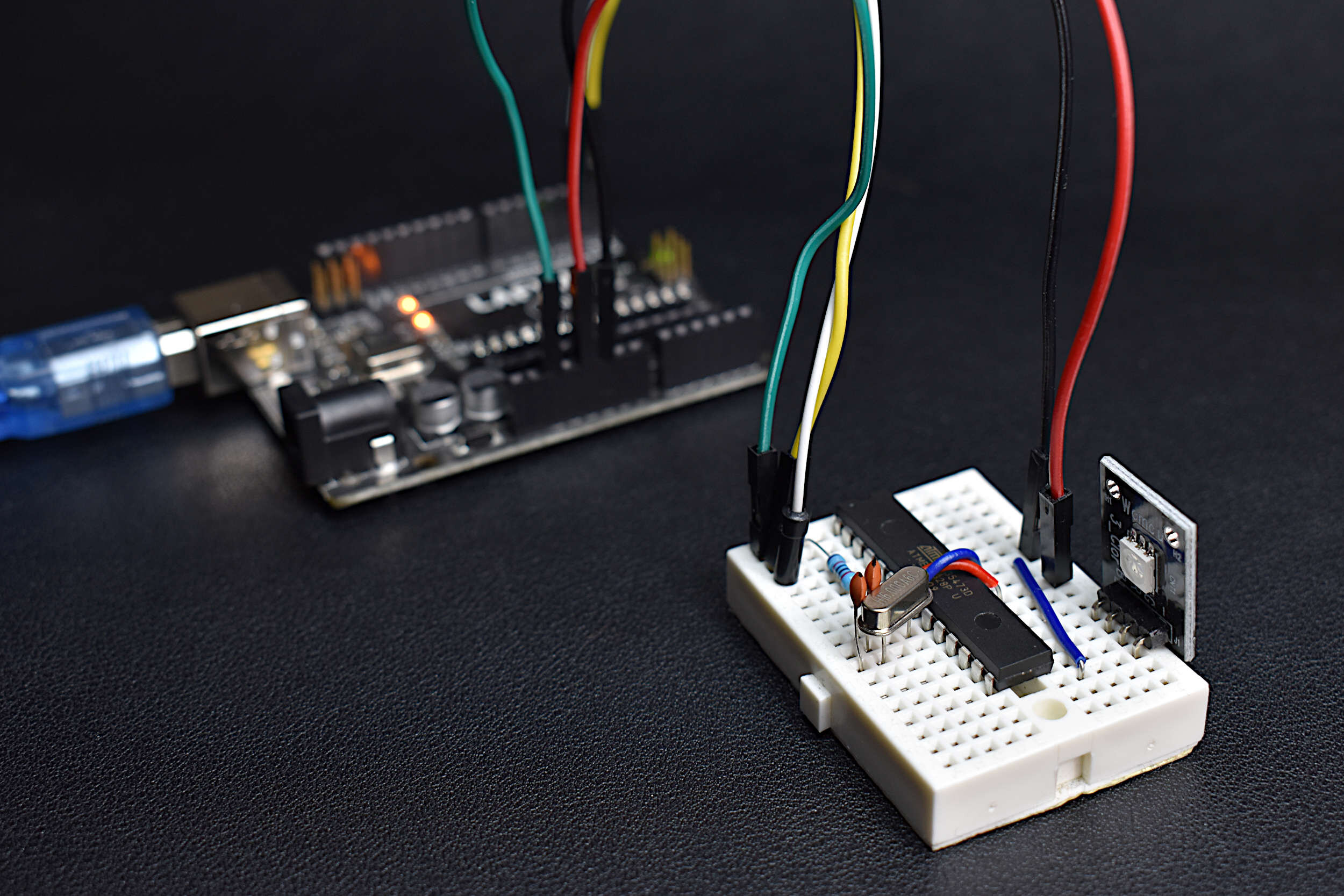
The wiring diagram and pinout table for the DIY Arduino board is given below:
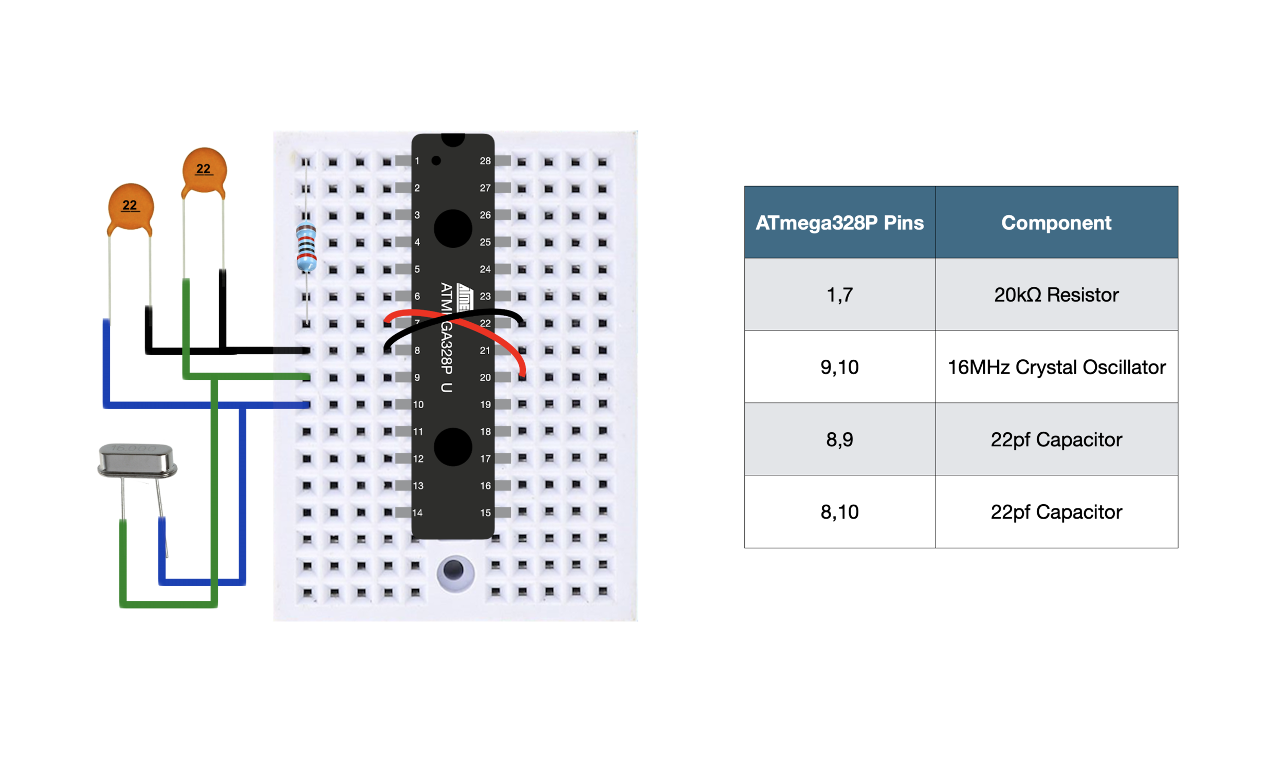
This wiring convention will be consistent throughout the entire tutorial, with additional wires needed in later sections when uploading code.
Uploading code to the DIY Arduino board is quite simple once the board is wired for USB communication. The wiring diagram for uploading code to the DIY Arduino board using the Uno Rev3 is given below:

TAKE NOTE: the ATmega328P chip in the Uno Rev3 board has been removed - this is mandatory when uploading code to the DIY Arduino board. If the ATmega chip is still in the Uno board, the code will go to that chip instead of the DIY board's chip.
At this point the DIY Arduino board is wired for USB to TTL communication, wherein the USB device (the Uno Rev3 in this case, with no ATmega chip) will program the DIY board. The Arduino IDE can now be opened, once the Uno Rev3 board is plugged into the USB port. Any code uploaded should be done so as if uploaded to an Uno board, with the standard Board selection (Arduino/Genuino Uno) and the Uno Rev3 as the Port, which should look similar to the following screenshot:

Everything is exactly the same as with an Arduino Uno board, and thus, we arrive at the DIY Arduino board that is capable of being programmed as an Uno board.
The following video is an example of a simple blinking LED code uploaded using the wiring method and Arduino IDE settings above:
Notice that only two jumper wires are needed for the DIY board. Once the code has been uploaded using the USB to TTL method (using the USART pins 2/3 on the ATmega328P), all the wires can be removed. The only two needed then are any voltage and grounding wires needed to power the device. Hence, the two wires in the video above.
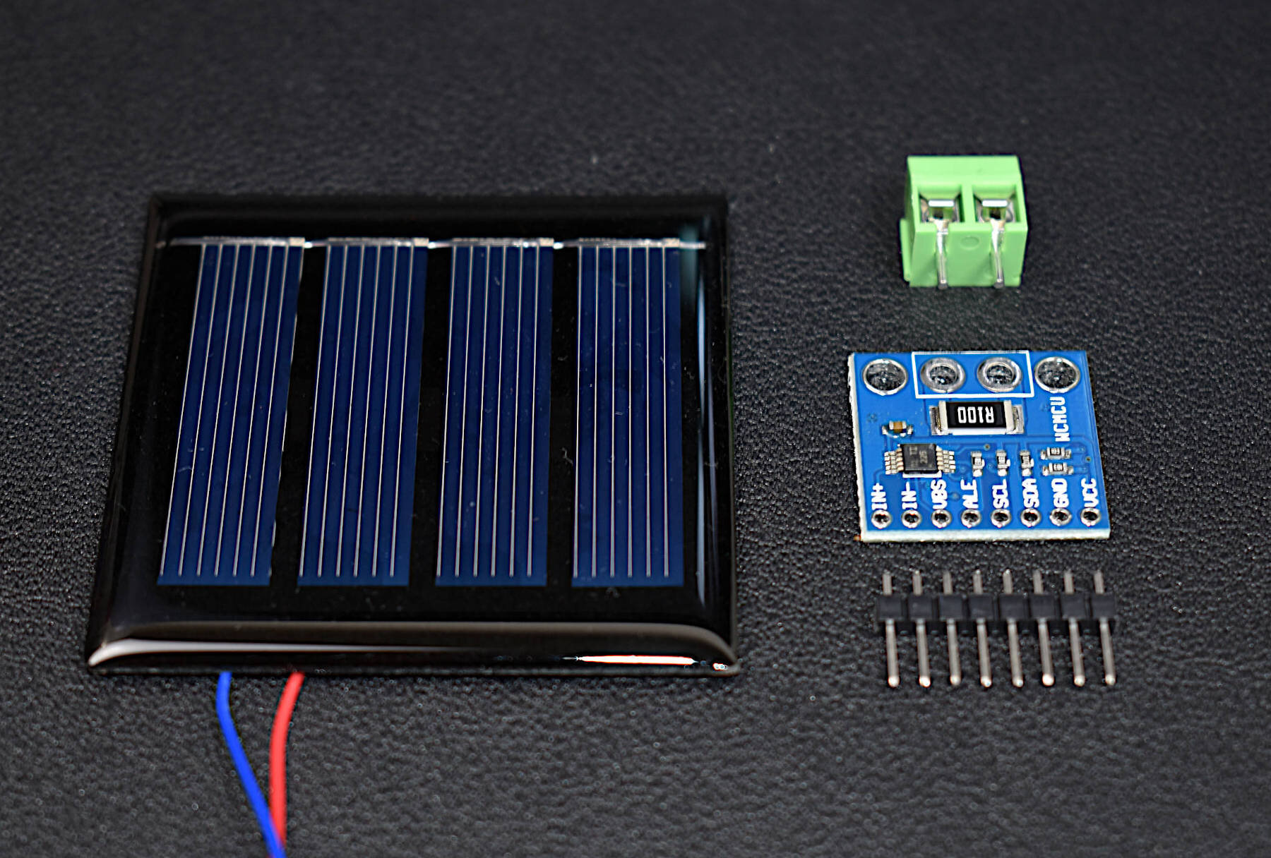
The most significant feature of the DIY Arduino board may be its adaptability. For example, being able to exchange the 16MHz quartz crystal allows users to control the power consumption of the board. Using a 4MHz crystal will give a much lower average power consumption than the 16MHz crystal. Furthermore, there is no regulator onboard, so the board can be powered at a lower voltage to further minimize the power consumption. Another advantage to the 2.7V - 5.5V voltage range of the DIY board is that a LiPo battery can be used as a power source, which permits creation of portable projects that don’t require a regulator.
The video below demonstrates the approximate power consumption of a board with a 16MHz crystal, 3.3V input voltage, and three different power cycles defined as follows:
15.6mA RGB LED Powered
8mA Idle Working Current
5µA Powered Down Sleep
The video demonstration of this is shown below for reference:
Some Features of the DIY Arduino Kit:
Fully-Functional Arduino Board
Low Power Consumption due to lack of LEDs or Regulators
Arduino Already Bootloaded onto the ATmega328P
Low Profile Breadboard, smaller than an Arduino Uno board
RGB LED for testing code
2.7V - 5.5V Operating Range
5µA Low Current when Powered Down (3.3V, 16MHz)
8mA Working Current (3.3V, 16MHz)
Jumper Wires for Uploading Code, and Interacting with Sensors and Motors
All of the features of the ATmega328P chip:
SPI, I2C, USART, PWM, ADC, Interrupts, Timers, etc.
Below is another video, this time demonstrating the PWM capabilities of the DIY board by showing a breathing LED phenomenon:
A DIY Arduino board was introduced here as a way to gain freedom in assembling an Arduino board for particular applications. The DIY board presented above is capable of very lower power modes, without the requirement of draining components such as LEDs or regulators. The ATmega328P chip is at the center of every Uno board (in recent years), and is also at the center of the DIY board, which allows the DIY Arduino to behave almost identically to the Uno board. Once the DIY board is wired for UART communication, it can be treated exactly as an Arduino Uno: from uploading code to interacting with motors and sensors. The DIY Arduino board has particular potential in low-power applications such as in Internet of Things meshes or portable sensors and controllers. This tutorial is meant as an introduction to the DIY Arduino and merely acts as a starting point for a serial of tests and explorations into the potential platform. In the next few entries, the board will be used to interact with various sensors over different protocols such as: I2C, SPI, and UART. The board will also be used to study low-power modes and power consumption, in order to explore its potential as a long-term wireless device controller and sensor node.
See More in Arduino and Electronics: