A Guide to Metal Core PCBs by PCBGOGO
Metal Core PCB Blog Index:

Reference: https://www.manncorp.com/pick-and-place-led-mc-ledv4-12.html
The use of LED based electronics has significantly increased in the past few years. They have proven to be more efficient and nearly 5 times cheaper than normal incandescent units. But with their use came one downside: heat. Some devices tend to use a number of LEDs that remain on for a long period of time and so can overheat. The LEDs are usually mounted on PCBs and can therefore cause significant damage. There is however one alternative to common PCBs i.e. metal core printed circuits (MCPCBs).
Metal Core PCBs or MCPCBs are the types of PCBs that contain a base metal material as opposed to the traditional FR4. The core is usually designed to redirect heat away from the components. The metal core is composed of a metal plate of a particular thickness which dissipates heat.

A MCPCB is essentially designed to improve the reliability of devices that run at slightly higher temperatures. Not only does it allow for components to be mounted but also draws heat from hot-running components to the other side of the board where it is dissipated. It has greatly helped to solve the problem of overheating caused by large number of LEDs in devices.

One of the major differences between the two is in the way the materials work. In MCPCBs there is a single layer of copper with is bonded to a layer of conductive dielectric material, which is further bonded to a thick metal layer (typically Aluminum 5052, Aluminum 6061, or Copper C1100). The dielectric used is approximately 6-7 times as thermally conductive as FR4. The dielectric is to be kept as thin as possible. This reduces the distance from the heat source to the metal plate which is more conductive than the dielectric.

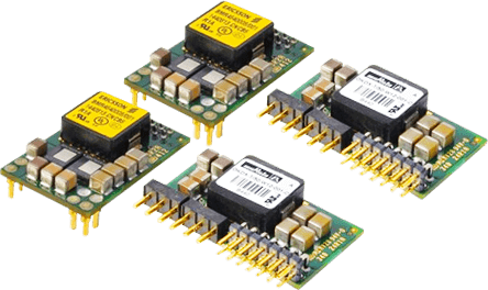
Reference: https://www.powerelectronicsnews.com/problems-solutions/power-supply-design-tutorial
The metal plate is the thickest element. The three most common thicknesses are 1.0mm, 1.5mm, and 3.2mm as they are the easiest to purchase. The metal also gives the PCB rigidity and does not require any surface finish or soldermask.
In a MCPCB, only surface-mounted components are to be used. This is because a plated through hole can cause a short circuit as the bottom layer is metal. In normal LED PCBs the layers usually have plated vias which allow components to transmit heat. During soldering some solder can enter these vias if not filled and can cause errors. On the other hand in MCPCBs operate differently.

Reference: http://www.circuit-technology.co.uk/images/user/16_crosssection_alcorepcb.png
Vias are not required as the metal layer is efficiently thermally conductive. Instead they require drilling of a few large mounting holes. This also helps the manufacturing process to move faster. After the drill cycle, the single layered MCPCB goes straight to circuit imaging rather than passing through the electroless copper deposition in PTH processing. After this the process is similar to the standard FR4 PCB.
Designing a single layered MCPCB is easy if you know how the process works. But if you wish for something other than a single layered PCB then other configurations are also available which are slightly different from the MCPCB configuration.
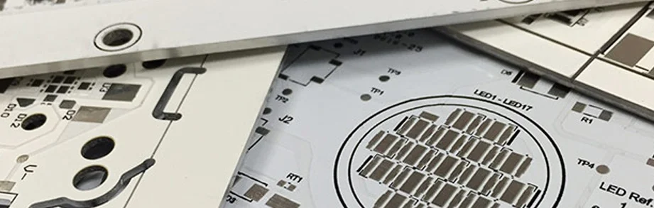
Reference: https://heros-electronics.com/Aluminum-PCB/142.html
For example:
· 2 layered PTH boards with aluminum on the inside. This requires a pre-drill, fill with insulation, and a re-drill to form PTH that won’t short.
· 2 or more layered boards built on standard PCB processing, using thermal dielectric material instead of FR4, and a metal plate laminated to the bottom for heat transfer.

1. FR4 has lower thermal conductivity (around 0.3 W) as compared to MCPCB (1-4 W)
2. FR4 uses plated through holes while MCPCB does not use PTH and instead uses SMT for its components.
3. FR4 PCBs use vias for heat transfer and have alonger drill processing cycle. MCPCBs do not require vias as they provide their own thermal dissipation. Consequently, they do not require via drilling, deposition and plating processes.
4. FR4 PCBs use soldermask in dark colors such as green, red, black etc. applied on top and bottom whereas MCPCB use only white and it is applied to the top only.
5. FR4 have a range of thicknesses and uses many material combinations and layers. MCPCBs have limited thickness variation.
6. FR4 PCBs use standard processing such as drilling, routing, v-scoring, countersink, counterbore etc whereas in MCPCBs there is a distinctive difference in the v-scoring process i.e. diamond coated saw blades are used for the added strain from cutting into metal.
PCB PROTOTYPE & PCB ASSEMBLY MANUFACTURING SERVICES BY PCBGOGO

See More in Engineering and Electronics: