Controlling LEDs with A Multiplexer and Arduino
In general, a demultiplexer uses N boolean outputs to control 2N switches. In our case, the CD4051 multiplexer will be used as a demultiplexer using 3 digital pins and boolean logic to control 8 individual LEDs. Several skills will also be developed, specifically with regard to programming in the Arduino programming language. Pulse-width modulation (or brightening and dimming) of LEDs will be explored, as well as randomization of LED blinks, along with the general selection process for boolean switching with the demultiplexer.

Project Sponsor: PCBGOGO.COM -> with over 10 years as an industry leader, PCBGOGO is one of the most experienced PCB and PCB assembly manufacturers in China
This tutorial will be straight-forward in that uses only an Arduino, multiplexer, and 8 LEDs. Therefore, the parts list is short:

CD4051B Multiplexer used for controlling up to 8 LEDs
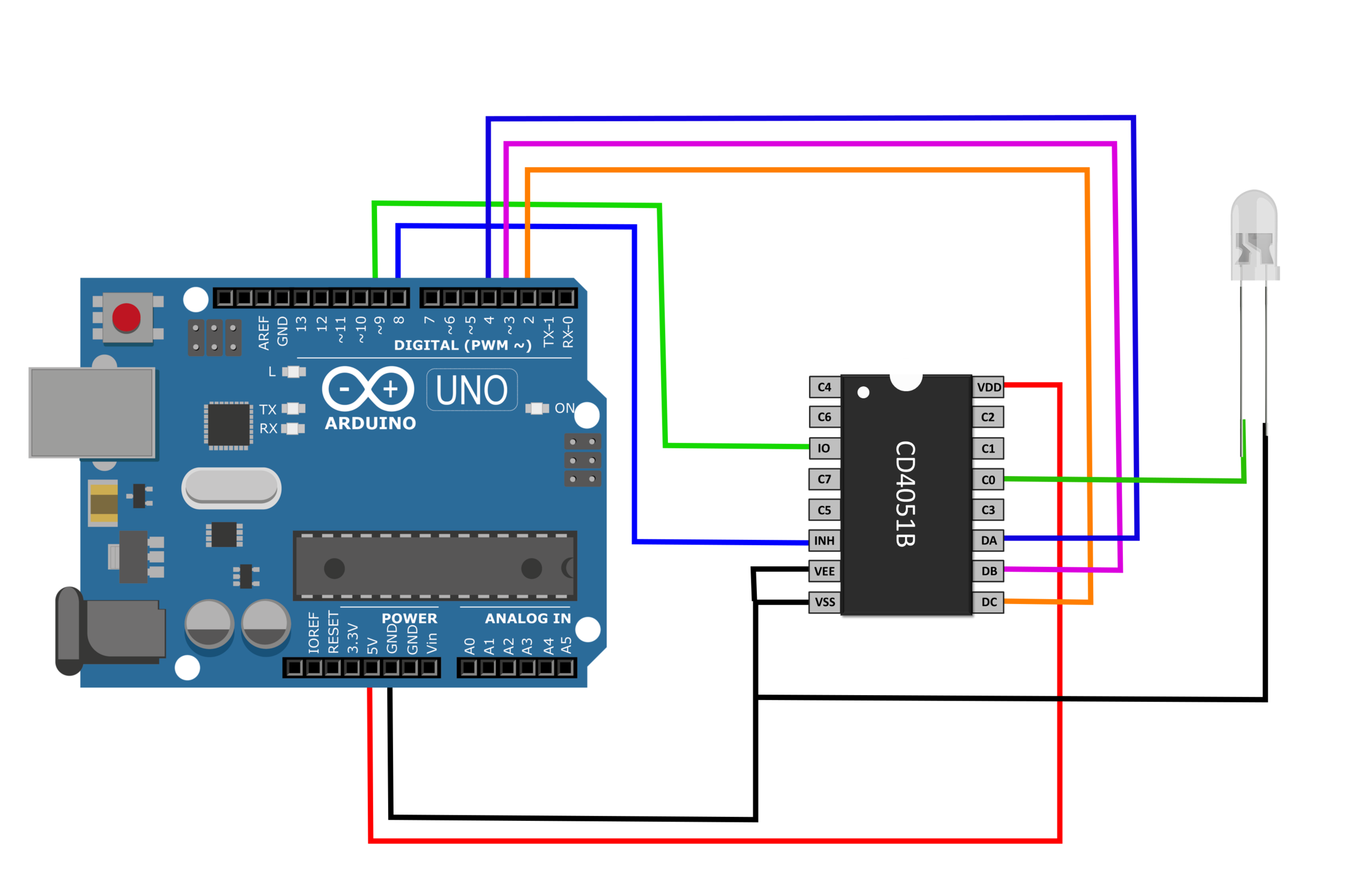
The CD4051 demultiplexing wiring require the IO pin to supply the pins C0-C7 with power, which is why the IO pin is wired to digital pin D9 on the Arduino. D9 was selected because it both can handle digital writing (normal on and off) of the LEDs as well as PWM (pulse-width modulation) which allows the LEDs to be dimmed. Moreover, the pins DA, DB, DC on the CD4051 act as the boolean inputs that handle which LED is being controlled. Pins D2, D3, D4 will handle the boolean control of the LEDs on the Arduino side. Lastly, the inhibit pin is on Arduino’s D8, which when set HIGH will turn off all of the LEDs.
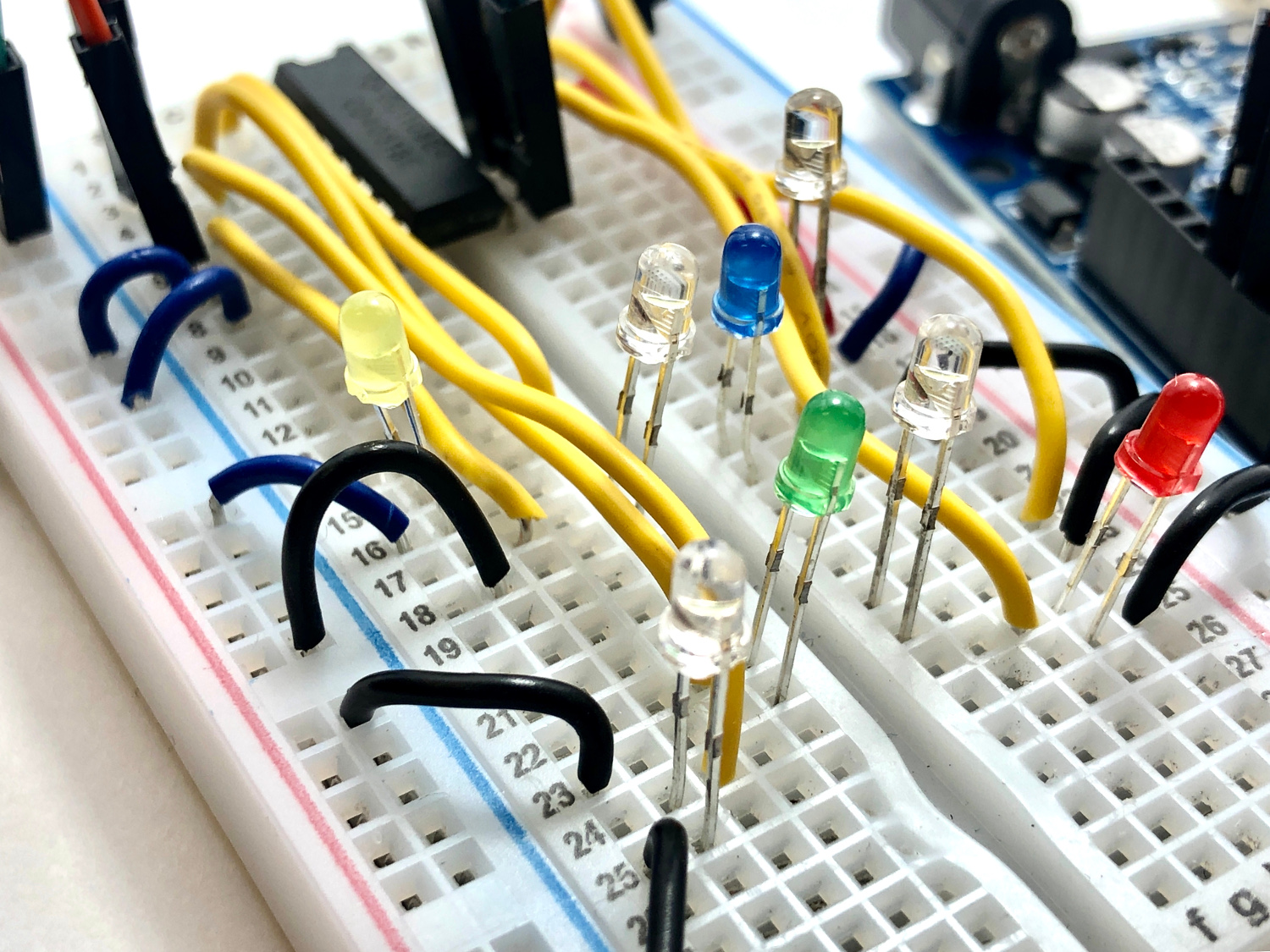
Only 1 LED is wired to the CD4051 in the image above, however, in the examples and demonstrations to follow it is assumed that 8 LEDs are wired from C0-C7 on their positive leg, and each negative leg to ground.
The boolean table for pins DA, DB, DC is shown below, outlining how the three pins select the LED to be controlled:
| Activated LED | DC | DB | DA | INHIBIT |
|---|---|---|---|---|
| C0 | LOW | LOW | LOW | LOW |
| C1 | LOW | LOW | HIGH | LOW |
| C2 | LOW | HIGH | LOW | LOW |
| C3 | LOW | HIGH | HIGH | LOW |
| C4 | HIGH | LOW | LOW | LOW |
| C5 | HIGH | LOW | HIGH | LOW |
| C6 | HIGH | HIGH | LOW | LOW |
| C7 | HIGH | HIGH | HIGH | LOW |
| NONE | X | X | X | HIGH |
The pins [DC,DB,DA] correspond to Arduino pins [D2,D3,D4], which will follow the states outlined in the table above in order to control the desired LED. Therefore, if we wanted to control the LED on CD4051 pin C6, we would need to alter the Arduino pins [D2,D3,D4] as such:
C6 on = [D2 = HIGH, D3 = HIGH, D4 = LOW]The first and simplest example is to align each LED in a sequence and wire them sequentially from C0-C7. The Arduino code is shown below, with comments describing each line:
int outputs[4] = {4,3,2}; // pins for selecting LED
int io_pin = 9; // pin used for sending power to LEDs
int inhibit_pin = 8; // pin for turning off all LEDs

void setup() {
  for(int ii;ii<3;ii++){
    pinMode(outputs[ii],OUTPUT); // output selection for LED control
  }
  pinMode(inhibit_pin,OUTPUT);
  digitalWrite(inhibit_pin,LOW); // raise high to disable all
  pinMode(io_pin,OUTPUT); // this controls the power sent to each LED
  digitalWrite(io_pin,HIGH); // send high to all LEDs when powered on
}

void loop() {
  // looping through all 8 LEDs
  for (int jj=0;jj<8;jj++){
    // turn on LEDs based on bit conversion
    for(int ii=0;ii<3;ii++){
      digitalWrite(outputs[ii],bitRead(jj,ii));
    }
    delay(100); // delay .1 sec
  }
}
The above code collapses a lot of the process involved in controlling the outputs on the multiplexer. Some implications of the code above are listed below:
The ‘for loop’ corresponding to ‘jj’ iterates through individual pins on the multiplexer C0-C7
The ‘for loop’ corresponding to ‘ii’ handles the conversion from integer value to binary control of the subsequent C pin
A video demonstration of the code above is shown below:
We can randomize the blinking sequence as well as the time between blinks. This will give the illusion of chaos in the LED blinking and creates a cool effect. An integer can be randomized using the following syntax:
int rand_int = random(min,max);
The only code that needs change in the above routine is the ‘void loop()’ - therefore, I have only included that section below.
void loop() {
  // randomly selecting LED to turn on
  int jj = random(8);
  // turn on LEDs based on bit conversion
  for(int ii=0;ii<3;ii++){
    digitalWrite(outputs[ii],bitRead(jj,ii));
  }
  delay(random(20,80)); // delay .1 sec
}
This randomization is also shown below in a video demonstration:
Pulse-Width Modulation changes the average amount of energy given to an LED to effectively change its brightness. We will use the ‘analogWrite()’ function to change the power given to each LED and create a dimming feature on the demultiplexer. This is done again by altering the code from the setup to the loop as follows:
int outputs[4] = {4,3,2};
int io_pin = 9;
int inhibit_pin = 8;

void setup() {
  Serial.begin(9600);
  for(int ii;ii<3;ii++){
    pinMode(outputs[ii],OUTPUT);
    Serial.println(outputs[ii]);
  }
  pinMode(inhibit_pin,OUTPUT);
  digitalWrite(inhibit_pin,LOW); // raise high to disable all
  pinMode(io_pin,OUTPUT); // this controls the power sent to each LED
}

void loop() {
  for (int mm = 0;mm<1024;mm+=10){ // change brightness in steps
    analogWrite(io_pin,mm); // pwm signal
    for (int jj=0;jj<8;jj++){
      for(int ii=0;ii<3;ii++){
        digitalWrite(outputs[ii],bitRead(jj,ii));
      }
      delay(100);
    }
  }
}
The code above loops through each LED and alters the brightness from minimum (0V) to maximum (5V) by changing the width of the signal sent to each LED. The width changes based on the analogWrite() function going from 0-1023. This is the essential function of the code above, which results in the brightness looping routine shown in the video below:
Several techniques in demultiplexing were explored here, specifically with respect to blinking LEDs. The CD4051B multiplexer makes blinking multiple LEDs very fast and easy. In this tutorial we blinked several LEDs in succession, randomly, and even changed their brightness using pulse-width modulation. Multiplexers and demultiplexers can be useful in applications where limited outputs or inputs are available or when universal applications are desired for multiple outputs. In this case, we were able to take three Arduino pins and transform their logical signals into controlling 8 individual LEDs. This is a case where we could’ve done the same with the Arduino pins, but the demultiplexer simplified the process by using only 3 input pins and a limited output (to prevent overloading the CD4051 IC). There are many application potentials to this technology, and in a similar tutorial, the general demultiplexer routine will be used along with a touch screen to change the location of the switched-on LED.

Special thanks to PCBGOGO for sponsoring this project.
PCBGOGO is a quick turn PCB fabrication and PCB assembly manufacturer
See More in Arduino and Electronics: