Arduino Servo Motor Basics and Control
“As an Amazon Associates Program member, clicking on links may result in Maker Portal receiving a small commission that helps support future projects.”
Servo motors can be found in robotic arms, cameras, lathes, CNC machines, printing presses, and other engineering applications where precision and repeated movement are required. Servo motors are often comprised of DC motors that use feedback mechanisms to move with great precision from one position to another. The low-cost servos that are found in maker projects use potentiometers to register voltages as positions on the rotating plane of the servo. Often, servo motors contain a series of gears that either speed up or slow down and smooth the movement of the DC motor. Lastly, servo motors use a circuit to control and send feedback information to a given controller, which in our case is an Arduino board (read more about servo motors here). In this tutorial, an Arduino board will be used to power and control a small servo motor. The basics and composition of an SG90 will be explored, and the application of several servo codes and applications will be given for another type of servo motor, the MG90S. The goal of this project is to introduce users into the workings of a servo motor, how PWM (pulse-width modulation) controls a servo motor, and how Arduino can interface with servo motors to produce desired movements to great precision.
The SG90 (datasheet here) is a 9 gram servo motor that can rotate 0 - 180 degrees (roughly) at a rate of about 0.3 seconds (0.1s/60 degrees). The SG90 is used in low-cost projects, typically with motorized vehicles and robotic arms. The SG90 is a great tool for education and prototyping - as it is inexpensive and easy-to-use. The SG90 is also compatible with the Arduino software, which will be used in this tutorial to rotate the servo in order to view how the gear reduction from the small DC motor gear to the larger and slower gear used in applications with the motor. See the next section for full Arduino wiring and code instructions.
Below is a series of photographs depicting the different components contained within a typical SG90 servo motor:

SG90 Micro Servo
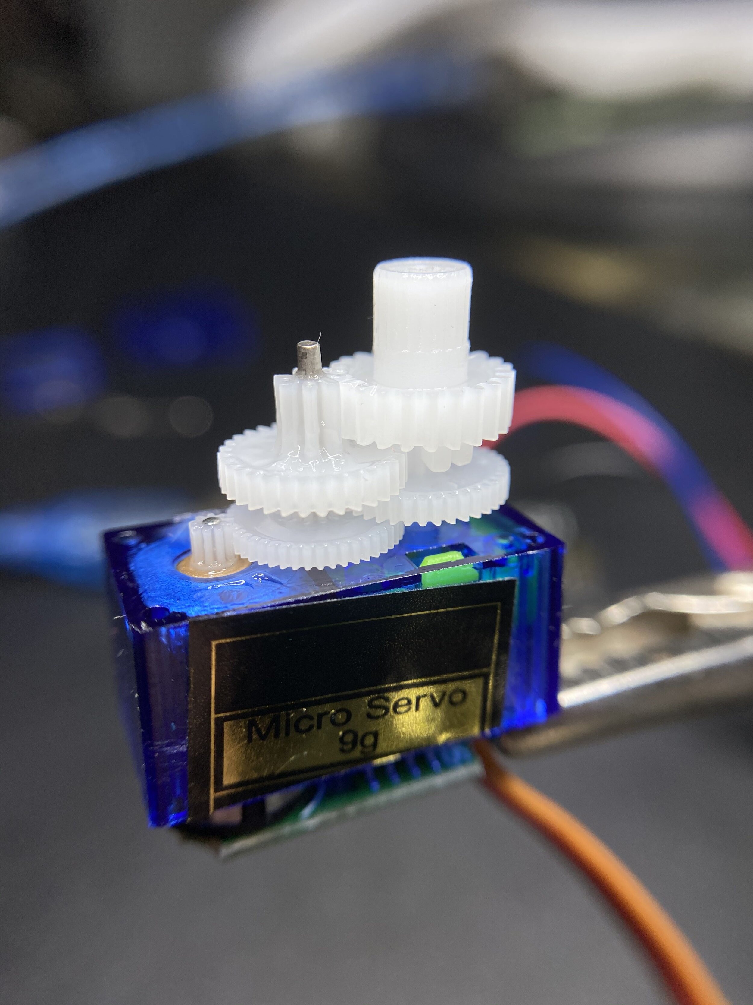
Close-up of SG90 Gears
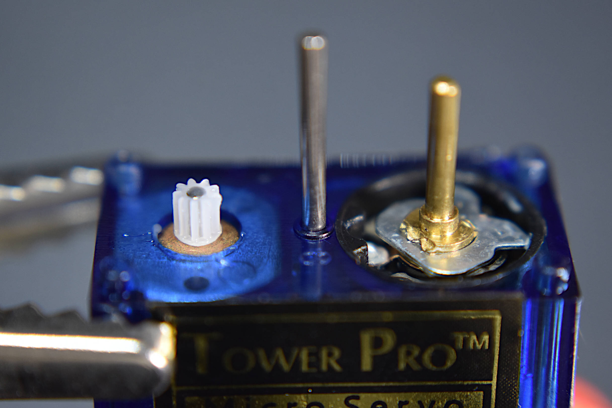
SG90 showing DC motor (left) and potentiometer (right, brass color)
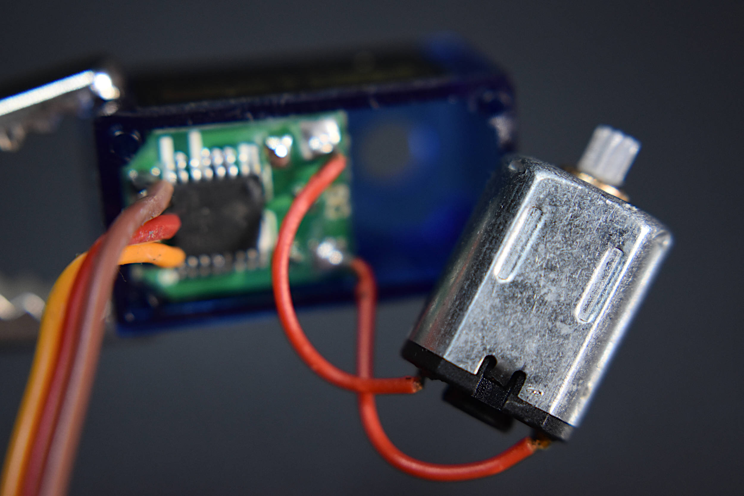
SG90 from bottom showing DC motor and Circuit
A video of the gear reduction process is shown below, where the DC motor is sent through a gear reduction stage, with a stabilizing gear phase (the middle pole in the image above with the motor and potentiometer), and finally the slower rotating gear which is used for applications (the top gear). The video shows the SG90 under 5.0V powered by an Arduino board, rotating 1 degree roughly every 17 milliseconds for 90 degrees and then stopping.

In the next section, another servo motor, the MG90S, will be used to demonstrate wiring and control of the servo with an Arduino board.
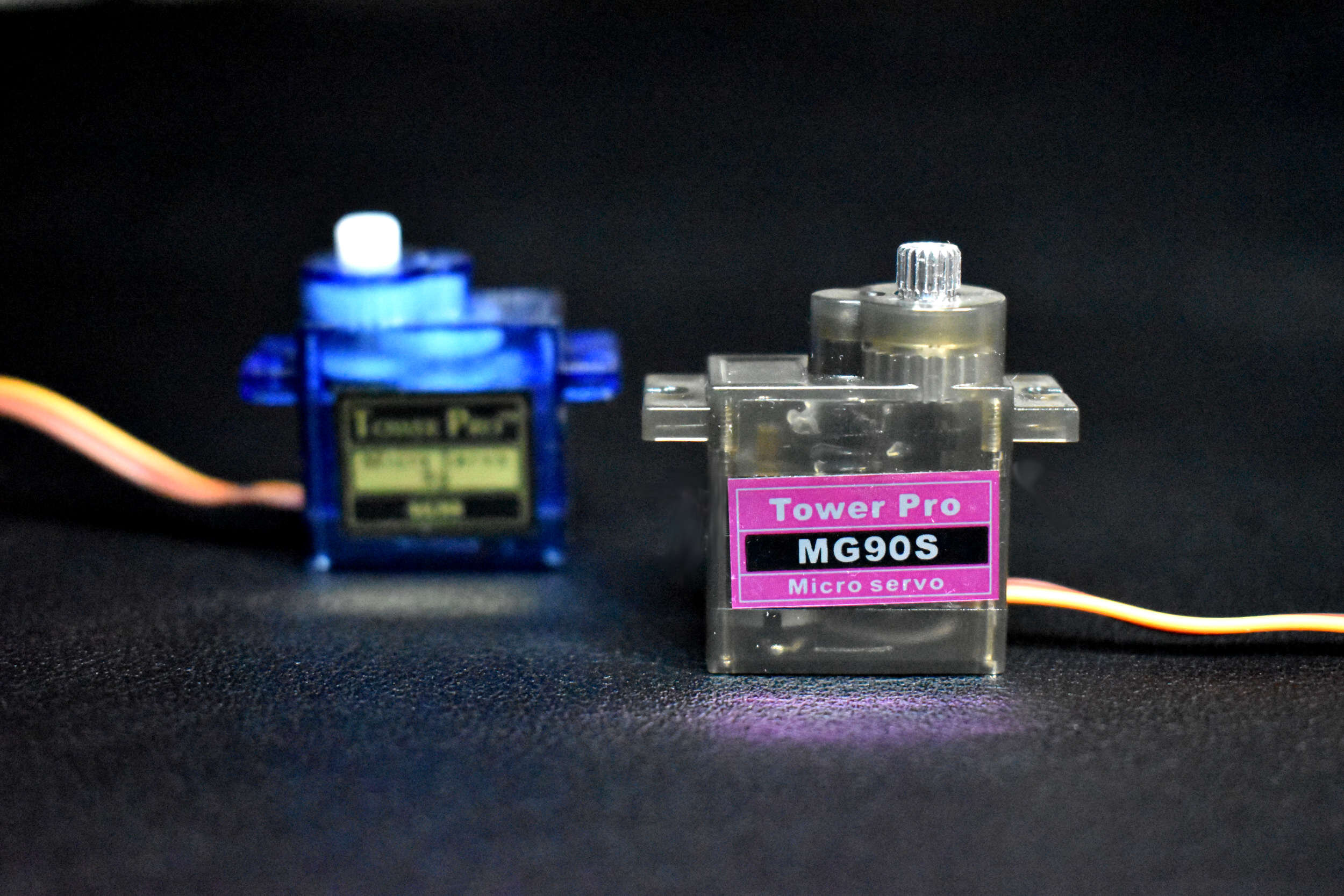
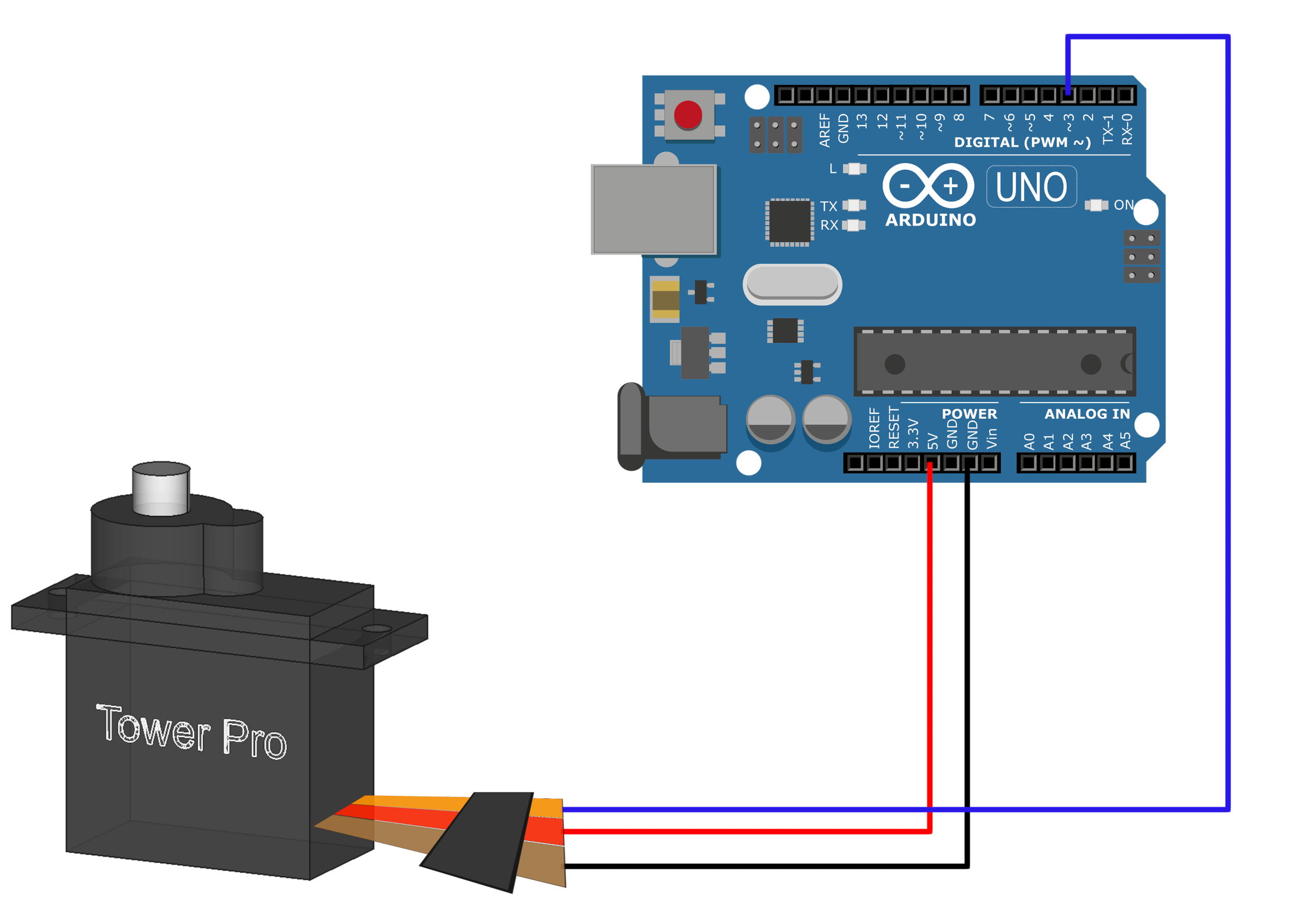
The MG90S is another small servo motor that is similar to the SG90, but weighs slightly more (14g) and has metal gears instead of plastic. The MG90S is also slightly faster than the SG90, which is a further justification for why it is used here. Both the MG90S and the SG90 are wired the same and use similar code. Right out of the box, MG90S servos work with the prescribed Arduino ‘Servo’ code, which rotates the servo back and forth based on its built-in servo library. The Arduino library is a great place to start, as it really only requires a few lines of code. First, the servo needs to be wired to an Arduino board. The Arduino Uno board is used below. The MG90S technically has a working voltage input range of 4.8V - 6.0V, so any 5.0V Arduino should work, assuming it has pulse-width modulation (PWM) capabilities. Fortunately, the Arduino uses a 20ms PWM pulse in its servo library, which happens to be the period of the PWM pulse on both servos, so the programming needed to get the servos functioning is minimal.

The MG90S Micro Servo is a 13g servo motor that is great for applications in low-cost robotics and automation. The MG90S can be powered directly from any 5.0V Arduino board, and can be controlled using the servo library included in most Arduino IDEs.
Included with the MG90S Micro Servo Package:
1x MG90S Micro Servo
1x Set of horns and screws (6 pcs)
3x Jumper Wires (Male-to-Male)
Some Features of the MG90S:
Input Voltage: 4.8V - 6.0V
Operating Current (5.0V): ~2.7mA (idle), ~70mA (no load), ~400mA (Stall)
Rotation Angle: 0° - 180° (Resolution: 1°)
Max Speed (5.0V): 0.6 deg/ms (full 180 degrees in 300 ms)
Largest Dimensions: 12mm x 32.5mm x 32.5mm
MG90S Datasheet
NOTE: These are not genuine Tower Pro motors
A full tutorial with the MG90S, including code and general working principles, is given here.
The simple code to replicate the .gif in the previous section is given below. The process carries out the following procedure:
First, rotate to 0 degrees to determine the starting point of the motor
Infinite Loop:
Rotate to 90 degrees in about 3 seconds, wait 5 seconds
Rotate to 180 degrees in 3 seconds, wait 5 seconds
Rotate back to 90 degrees in 3 seconds, wait 5 seconds
Rotate back to 0 degrees in 3 seconds, wait 5 seconds
#include <Servo.h>

Servo servo_1; // servo controller (multiple can exist)

int servo_pin = 3; // PWM pin for servo control
int pos = 0;    // servo starting position

void setup() {
  servo_1.attach(servo_pin); // start servo control
}

void loop() {
  for (pos = 0; pos <= 180; pos += 1) { // goes from 0 degrees to 180 degrees
    // in steps of 1 degree
    servo_1.write(pos);              // tell servo to go to position in variable 'pos'
    delay(15); // delay to allow the servo to reach the desired position
    if (pos==90){
      delay(5000); //wait 5 seconds once positioned at 90 degrees
    }
  }
  delay(5000); // wait 5 seconds after reaching 180 degrees

  for (pos = 180; pos >= 0; pos -= 1) { // goes from 180 degrees to 0 degrees
    servo_1.write(pos);              // tell servo to go to position in variable 'pos'
    delay(15);
    if (pos==90){
      delay(5000); // wait 5 seconds once positioned at 90 degrees
    }
  }
  delay(5000); // wait 5 seconds after arriving back at 0 degrees
}
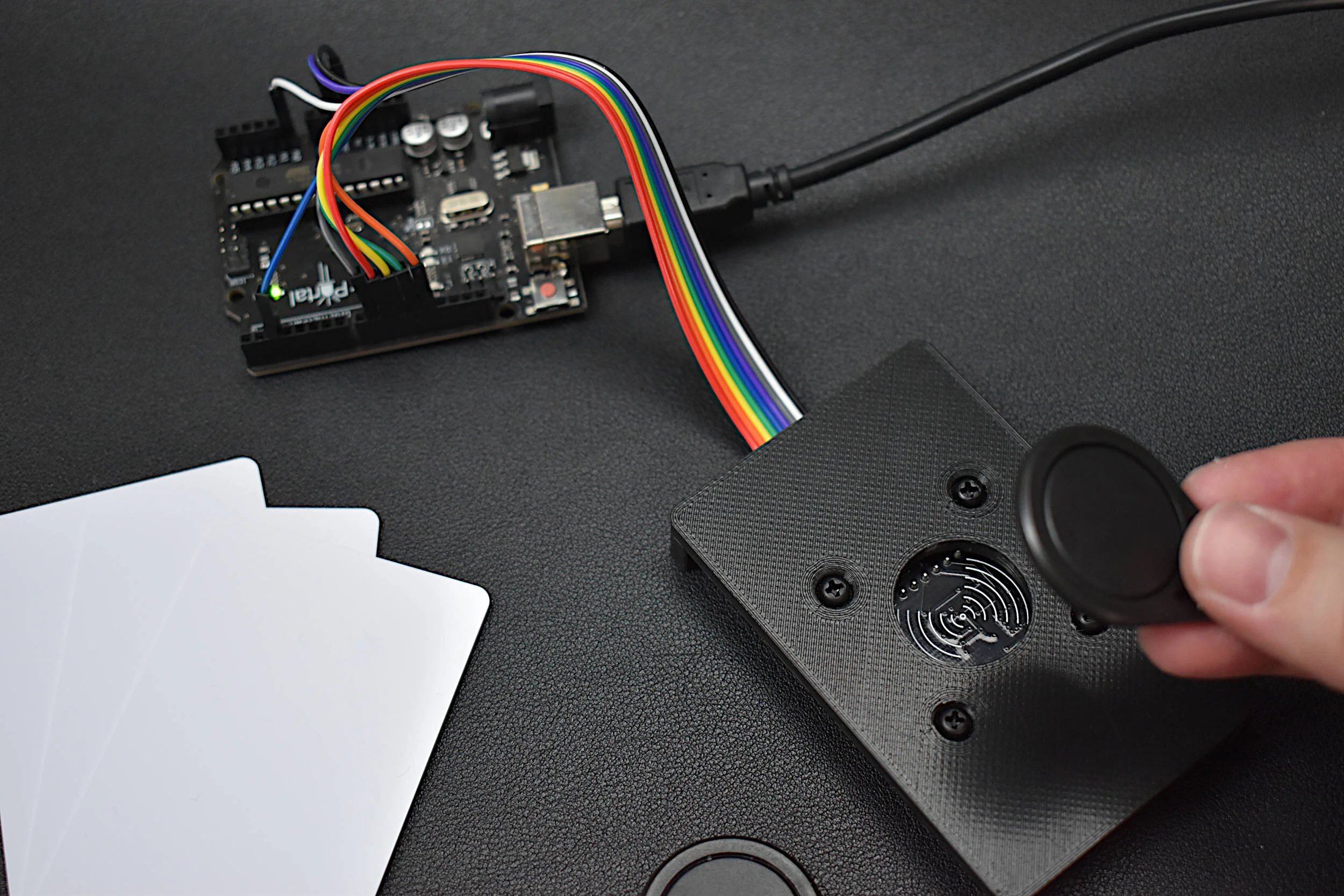
Now that the basics of wiring and coding a servo have been introduced, more advanced topics on using and controlling servos can be explored. In this section, the focus will be on controlling a servo using the serial port. In short, an inputted angle to the serial port (in degrees) will tell the Arduino to turn the servo to the given position. This type of control could be useful for robotic arms, camera control, or any situation where the angle is known and needs to be changed according to a user’s direct input.
Some of the implementations used here have also been used in previous tutorial, where an RGB LED was controlled using the serial port on an Arduino. That tutorial can be found here where the control of Arduino pins is explored in great detail. Here, the focus is just on controlling a single Arduino pin to change the angle of the servo motor using pulse-width modulation.
#include <Servo.h>

Servo servo_1; // servo controller (multiple can exist)

int servo_pin = 3; // PWM pin for servo control
int pos = 0;    // servo starting position

void setup() {
  servo_1.attach(servo_pin); // start servo control
  Serial.begin(9600); // start serial monitor
  servo_1.write(pos); // move servo to 0 degrees
  Serial.println("Positioned at 0 Degrees");
  Serial.println("Input Desired Angle and Press Enter");
}

void loop() {
  while (Serial.available()){
    String in_char = Serial.readStringUntil('\n'); // read until the newline
    Serial.print("Moving to: ");
    Serial.print(in_char);
    Serial.println(" Degrees");
    servo_1.write(in_char.toInt()); // convert angle and write servo
    delay(in_char.toFloat()*(10.0/6.0)); // delay for maximum speed
  }
}
Note: Ensure that the serial monitor is printing a 'Newline' every input (check next to 9600 baud)
The output of the code above should look something like this in the serial monitor:
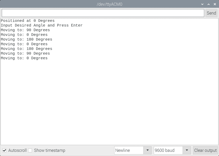
Serial Monitor Output During Control of MG90S Servo
A video of the sequence above is shown below:
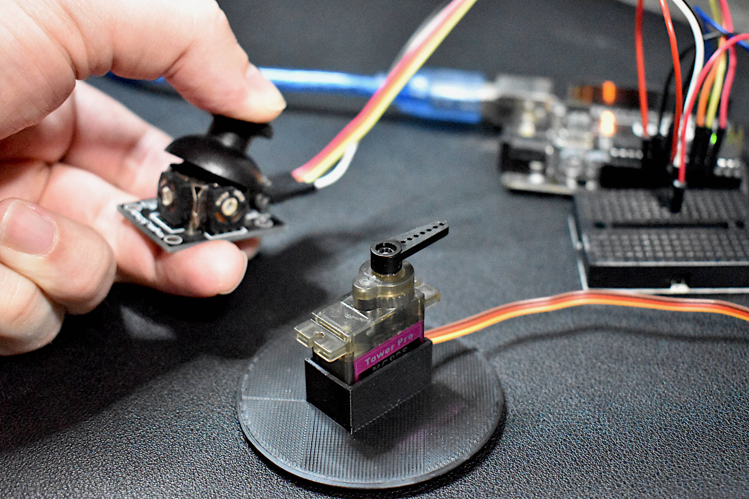
A joystick can also be used as a control tool for a servo. The methodology involves some geometry and understanding of how a joystick works, but it is not too complicated. A joystick rotates in a 2-D plane (most have a third dimension as well - force, but that will not be discussed here). Using Arduino again, we can record the x and y-direction movements of the joystick and translate them into angular movements.
The geometric motion of a joystick can be depicted as follows:

Analog joysticks can be found in video game controllers, drone and remote-controlled vehicle controllers, and heavy machinery controllers. They’re great for just about any precision control project where human interfacing is desired. The analog joystick here is one that is compatible with both Arduino and Raspberry Pi - and is a great tool for learning coding, robotic control, and functional interaction between humans and computers.
Included in the Analog Joystick Package:
1x Analog Joystick Controller
5x Female-to-Male Jumper Wires
Some Features of the Analog Joystick:
5V Input Supply
2-D Rotational + 1-D Push Analog Responses
360° Rotation in 2-D Plane
Rubber Joystick Finish for Gripping
Smooth Rotation
Clicking sound for Push Notification
Compatible with Raspberry Pi + Arduino
Code for measuring joystick rotations can be found at this tutorial:
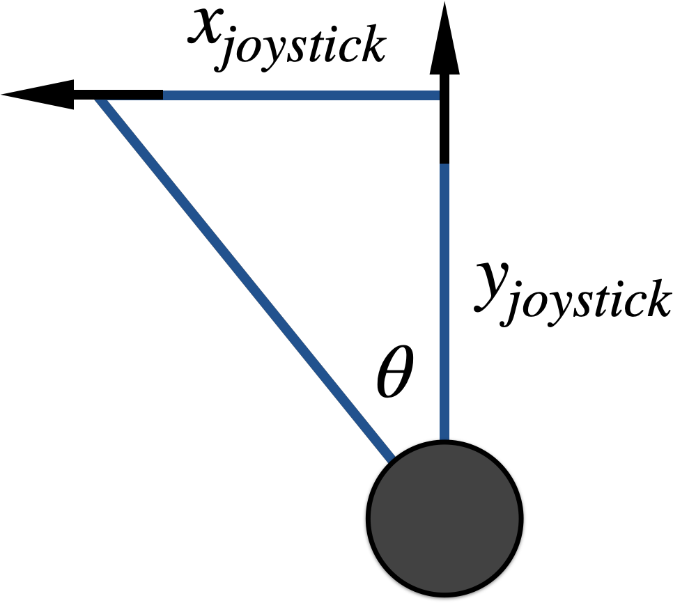
where the black dot in the triangle is the knob that is moved on a joystick, and the motion convention follows the arrows. The greek symbol θ represents the angle with which the joystick is operating, and will also determine where the servo motor will be positioned.
We can solve for θ using the tangent function:

An implementation of the angle has been carried out in Arduino using its ‘atan2()’ function which outputs the approximate angle between two directional components. Below is the full Arduino code that implements the inverse tangent for the joystick values. It also incorporates an offset which makes the movements of the joystick mimic the angular movements of the servo. The angle output by the inverse tangent spans the negative values, so the angle has been corrected to both rotate for negative values and mimic the rotational convention of the MG90S servo. Lastly, a jitter reduction routine is used to prevent the servo from moving too much without much joystick movement. All of this is part of the code below:
#include <Servo.h>
#include <math.h>

Servo servo_1; // servo controller (multiple can exist)

int servo_pin = 3; // PWM pin for servo control
int joy_pin_x = A0; // pin for x-dir joystick
int joy_pin_y = A1; // pin for y-dir joystick
int offset_x = 0; // subtracting the initial joystick x-location
int offset_y = 0; // subtracting the initial joystick y-location
int pos = 90;    // servo starting position aligned with joystick
int prev_deg = 0; // bound for reducing jitter
int x_prev = 0; // bound for reducing jitter
int y_prev = 0; // reducing jitter

void setup() {
  servo_1.attach(servo_pin); // start servo control
  Serial.begin(9600);
  servo_1.write(pos); // move to center (joystick neutral)
  Serial.println("Positioned at 90 Degrees");
  offset_x = analogRead(joy_pin_x); // initial joystick x-val
  offset_y = analogRead(joy_pin_y); // initial joystick y-val
}

void loop() {
  int x_val = analogRead(joy_pin_x)-offset_x; // relative joystick x
  int y_val = analogRead(joy_pin_y)-offset_y; // relative joystick y
  if (abs(x_prev-x_val)<10 and abs(y_prev-y_val)<10){
    // reduce jitter
  } else {
    x_prev = x_val;
    y_prev = y_val;
    float deg = 180-(int(atan2(x_val,y_val)*(180.0/PI))+90); // angle calc
    if (abs(deg-prev_deg)>2 and deg>0 and deg<180){
      servo_1.write(deg); // move servo to joystick location
      delay(abs(deg-prev_deg)*(10.0/6.0));
      prev_deg = deg;
      Serial.println(deg); // print out degree
    }
  }
}
Servo motors are necessary for engineering applications both in the consumer market and industrial market. Servos can be found in aircraft, robotic arms, CNC machines, printers, cameras, and a multitude of other mechanically-functioning areas that require speed, precision, and effectiveness in control. In this tutorial, two servo motors were explored. One servo motor, the SG90, was used to demonstrate the inner components of a servo motor. The second servo, the MG90S, was used to demonstrate two particular applications of control. Using Arduino as the control point, the serial input was used as a way of inputting a desired angle and having the servo rotate to that position. Second, a joystick was used to respond to mechanical movements in two-dimensions, which were transformed into an angular response to make the servo rotate. This tutorial is the first entry in a series dedicated to motors and actuators, which will help engineers and makers explore the world of electromechanical movements.
See More in Arduino: