Arduino LoRa Network Part I: Radio Basics and Range Tests
“As an Amazon Associates Program member, clicking on links may result in Maker Portal receiving a small commission that helps support future projects.”
LoRa is a long range wireless radio technology that is applicable where Bluetooth and WiFi are unavailable or incapable of transmission, particularly over large distances. The LoRa framework harnesses high power, low frequency communication to transmit smaller packets of information. LoRa modules, such as the SX1276 used in this tutorial, are also widely available and relatively inexpensive, all while being fully compatible with Arduino. LoRa modules are also modular in software and hardware: transmission power is configurable, the modules can be outfitted with antennae, and transmission speed and packet information size are both modifiable. In this tutorial, an Arduino board and SX1276 modules will be used to create a network of long range (LoRa) nodes designed to communicate and transport information. The use of antennae will also help broaden the range of the nodes, and tests in New York City will help quantify the efficiency and cone of functionality for such a node in a complex environment.
LoRa is a portmanteau of the words Long and Range, designed as a solution to the short range limitations of WiFi and Bluetooth. LoRa was conceived as a Wide Area Network (WAN), specifically for integration into the Internet of Things (IoT). LoRaWAN® describes a long range, wide area, low power network of devices that can be used as bi-directional nodes with secure communication and ample freedom for customization in speed, transmission/reception distance, and information packet size. LoRa devices are typically great for sparse networks of sensors or areas where Bluetooth or WiFi are inaccessible or cost ineffective. Read More about LoRa at the official LoRa Alliance® site.
LoRa is similar to Bluetooth and WiFi in that it operates in a frequency band allocated to industrial, scientific, and medical (ISM) applications (read more about frequency allocations at this FCC link). The LoRa ISM band permitted in the U.S. is the 902-928 MHz band, while Bluetooth and WiFi operate in the 2400-2483.5 MHz and 5725-5850 MHz (5G WiFi) bands (more on the history of permitted bands here). This is also why many LoRa modules cite 915MHz as an operating frequency, because 915MHz is the center frequency of the FCC-allocated band in the United States. Just as a reference and for the curious, I have added a chart below that breaks down the allocation of each frequency band from 9kHz - 300GH. The ISM bands can be seen written below each respective band. A zoomable chart can be found on the National Telecommunications and Information Administration’s (NTIA) site.
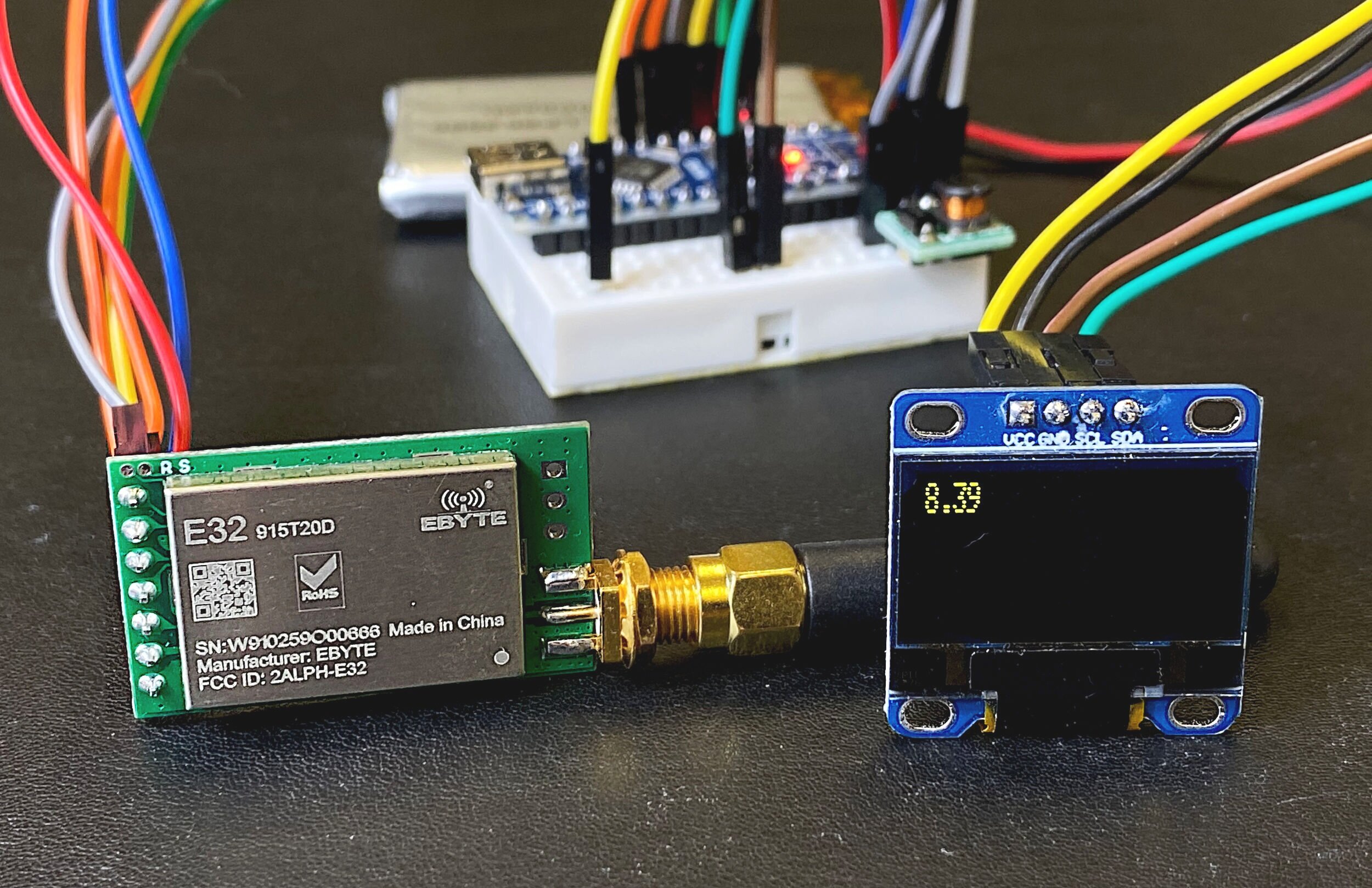
EBYTE is a Chinese electronics company that produces a line of LoRa modules ranging in frequency and power output. An E32-915T30D will be used as the base station for the LoRa network, and E32-915T20D modules will be used as the nodes. The T20D are 20dBm modules and the T30D are 30 dBm modules, where dBm represents the power output of each module in decibels with reference to 1mW. We can write dBm using the equation:
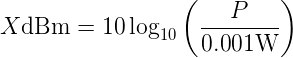
where:
X ≡ Power output [dBm]
P ≡ Power output [mW]
in the case of the 20 dBm module, the rough calculation of power requirement can be calculated by inverting the equation above:

This results in the approximate power requirement of:
T20D: P = 100 mW
T30D: P = 1 W
These results are important because they define the amount of power required to energize the module. The datasheets for each module can be found for the T20D here and the T30D here. The power outputs can also be used to quantify the effective distance of transmission of each module. A paper on the specifics of radio waves and path loss can be found on the IEEE called: “A Survey of Wireless Path Loss Prediction and Coverage Mapping Methods.”
An approximation of the attenuation experienced by the LoRa TX to the RX node is given by the classic Friis transmission equation in free air:

where:
Urx ≡ Receiver Power [W]
Utx ≡ Power output [W]
λ ≡ Wavelength of radio wave [m]
d ≡ Distance between TX and RX antenna [m]
β ≡ Directivity and path-dependent variable
The Friis propagation can be visualized below:

We can also convert to decibels to transform the variables into the traditional way of understanding radio power and attenuation:

And by solving for d, we can now approximate the effective path of the LoRa device (or any radio device):

For 915 MHz waves, an approximation of β equal to 1, and adding in the gain of each antenna, we arrirve at the following rough estimate of detectable signal distance:

NOTE:The distance approximation above is for free-air propagation, which is likely the maximum transmission range for a given setup. Methods for better approximation in suburban, urban, and other environmental conditions can be found in relevant literature.
If we were to use the cited sensitivity of -146 dBm for each module, and a transmitting power of 30 dBm, plus an antenna of 5 dBi, we get a distance approximation of 30,000 km! However, if we go to the manufacturer’s datasheet, EBYTE claims an 8 km transmission range for the T30D module, and a 3 km range for the T20D module.
What is happening here?
The best way to think of it is by going back to the β parameter. Often, users will add onto the path loss some Pβ that is associated with several parameters in the system, such as noise, directionality, atmospheric effects, etc. The Pβ variable is sometimes called the fade margin, and can be very large to account for a multitude of path obstacles and interferences.
The value of the fade margin in this case is likely around 71 dBm, which is fairly high. It is also entirely possible that our path loss method is incorrect and does not account for some of the conditions of the manufacturer’s testing.
More in-depth examples of fade margins and path loss and calculations that can improve the approximations of radio communication efficiency can be found in the literature citations below:
Empirical formula for propagation loss in land mobile radio services by M. Hata
The Link Budget and Fade Margin by Campbell Scientific, Inc.
The LoRa Protocol Technical Brief by John Sonnenberg at Raveon Technologies Corp
Path loss measurements for a non-line-of-sight mobile-to-mobile environment by J. Turkka and M. Renfors
RF link budget analysis in urban propagation microcell environment for mobile radio communication systems link planning by Ardavan Rahimian and Farhad Mehran
The range of the LoRa modules will also be tested in New York City, where the path loss will be even more complex. We will likely see variations in range based on directionality and building heights - so the exploration of the true urban range of the LoRa wide area network will be tested and quantified. In the next section, wiring the LoRa modules to Arduino is outlined, along with a list of parts used in this tutorial series.
The EBYTE modules will communicate with Arduino using the Universal Asynchronous Receiver-Transmitter (UART) protocol. The use of UART simplifies the wiring and process needed to carry out the communication between Arduino and LoRa device. There is also a fantastic and simple Arduino library written by KrisKasprzak that allows the user to easily interface with the E32 LoRa modules and Arduino. Since this is an IoT project, I will be using two Arduino boards and two LoRa modules. Any amount of LoRa modules can be used here, but to keep the process simple and to avoid confusion, I am only using one node and one base station. The E32-915TXXD LoRa modules use 7 pins to communicate over serial. The datasheets for both modules used here are given below:

Included in Package:
E32-915TXXD LoRa Module
Antenna
Features of E32-915T20D LoRa Module:
3.3V - 5V Supply
120mA TX Current, 14mA RX Current, 4μA Sleep Current
Data Rates configurable from 0.3kbps - 19.2kbps
Operating Frequency 900MHz-931MHz (fully permitted in USA)
Open Air Distance ~3km
TX Power ~20dBm, RX Sensitivity ~-146dBm
UART TTL Serial Protocol
Based on SX1276 LoRa IC
Fully Compatible with Arduino boards over Serial UART Communication
E32-915T20D Full Datasheet here
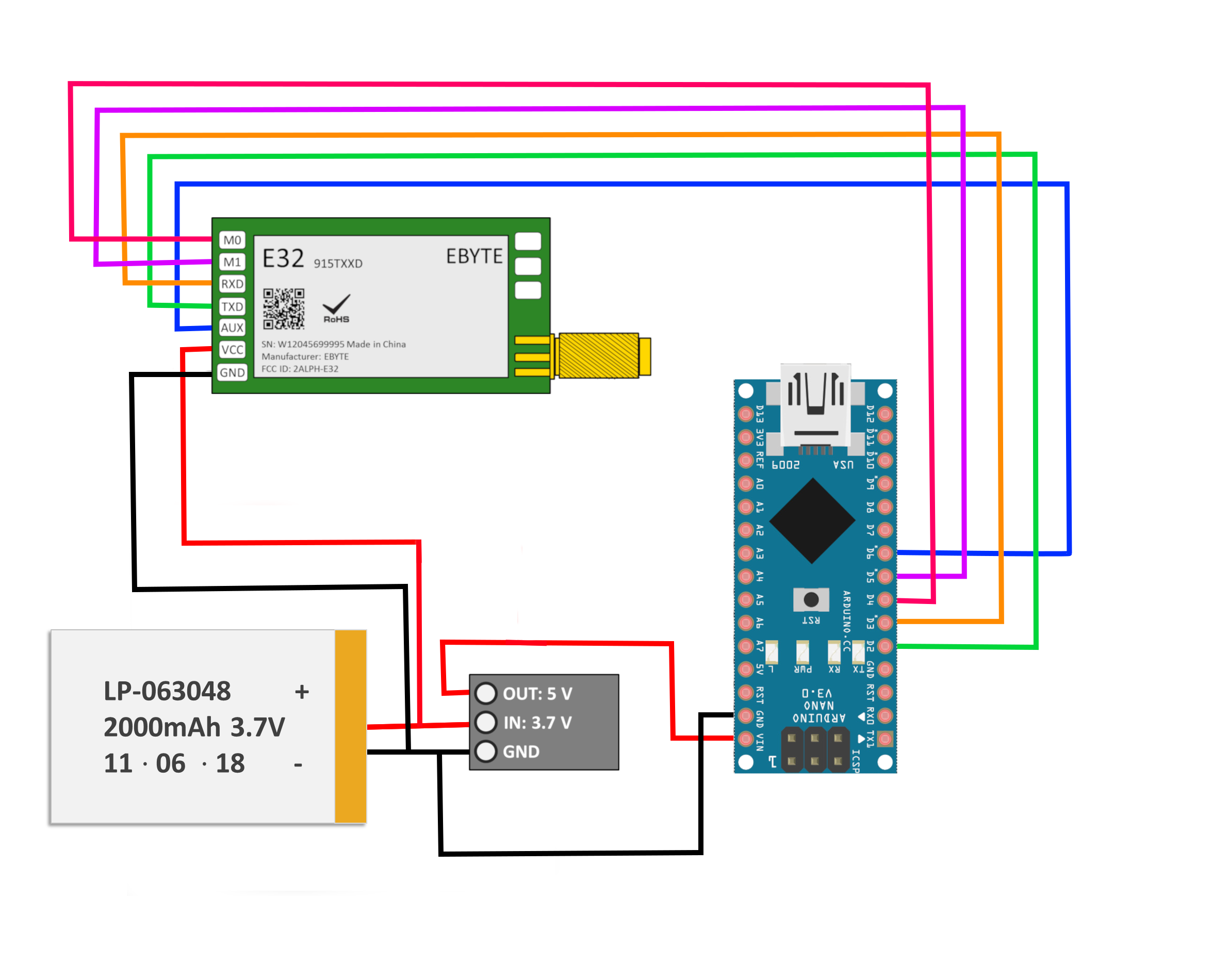
| E32 Pin | Arduino Pin | Description |
|---|---|---|
| M0 | D4 | Works with M1 to decide working mode of module (use resistor in series) |
| M1 | D5 | Works with M0 to decide working mode of module (use resistor in series) |
| RXD | D3 | RX for UART communication |
| TXD | D2 | TX for UART communication |
| AUX | D6 | Notifies Arduino of various working conditions (can also be used as external interrupt) |
| VCC | - | Powered by LiPo battery |
| GND | - | Ground by LiPo battery |
It is recommended for 5V Arduino boards (Nano, Uno, Mega) that 1k-5k resistors be used on the AUX and TXD pins to prevent any burnout issues. I tested the Nano and Uno boards and did not find any issues with burn up, however, the manufacturer suggests using the pull-ups just to be cautious. Also, notice that the LiPo is directly powering the LoRa modules - this is because they require 100 mW - 1 W depending on the module, and this is a bit too much to ask from the Arduino boards. Moreover, if we were to wire the 1 W module to the step-up converter, we would surely burn it out as well. Another thing to note: the 1 W module may work better with a higher voltage - the datasheet for the E32-915T30D states that 5V could achieve the best output power, but I have not tested this. Everything stated from here is based on each LoRa module powered with 3.7V and unlimited current.
The full parts list for the project is given below:
915 MHz EBYTE LoRa Module (30 dBm with +2 dBi Antenna) - $35 [Our Store]
915 MHz EBYTE LoRa Module (20 dBm with +3.5 dBi Antenna) - $35 [Our Store]
Arduino Nano - $13.99 (3 pcs) [Amazon]
1200 mAh LiPo Battery - $22.99 (5 pcs) [Amazon]
Mini Breadboard - $6.00 (2 pcs) [Our Store]
3.7V to 5V Step-Up Converters - $7.99 (2 pcs) [Amazon]
Jumper Wires - $6.98 (120 pcs) [Amazon]
The wiring is the same for both nodes between the Arduino nano and E32 LoRa modules, and is given below (adhering to the table above):
In the next section, the EBYTE library will be introduced and receiver and transmitter codes will be uploaded to each board.
As mentioned above, KrisKasprzak wrote a library that perfectly interfaces between Arduino and EBYTE LoRa modules. The library simplifies the processes outlined in the datasheet to control each module’s power output, air data rate, among other pararmeters. Below is the transmitter example code that introduces some of the syntax used by the library:
// Transmitter code for Arduino x E32 LoRa
#include <SoftwareSerial.h>
#include "EBYTE.h"

#define PIN_M0 4
#define PIN_M1 5
#define PIN_AX 6

float ii = 0.0;

SoftwareSerial ESerial(2, 3);
EBYTE Transceiver(&ESerial, PIN_M0, PIN_M1, PIN_AX);

void setup() {
  ESerial.begin(9600);

  Transceiver.init();
  Transceiver.SetMode(MODE_PROGRAM);
  Transceiver.SetTransmitPower(OPT_TP30);
  Transceiver.SetUARTBaudRate(UDR_9600);
  Transceiver.SetAirDataRate(ADR_300);
  Transceiver.SetAddressH(0);
  Transceiver.SetAddressL(0);
  Transceiver.SetChannel(13);

  Transceiver.SaveParameters(PERMANENT);
  Transceiver.Reset();

  Transceiver.PrintParameters();
  Transceiver.SetMode(MODE_NORMAL);
  Transceiver.Reset();
  ESerial.flush();
}

void loop() {
  ESerial.println(ii);
  smartdelay(2000);
  ii+=0.01;
}

void smartdelay(unsigned long timeout){
  unsigned long t = millis();
  while (digitalRead(PIN_AX)== LOW){
    if ((millis()-t)>timeout){
      break;
    }
  }
  t = millis();
  while ((millis()-t)<20){};
}
The general process for using the EBYTE library is as follows:
ESerial.begin(9600) - starts UART comm. with E32 module
Transceiver.init() starts the communication between E32 modules (TX and RX)
Transceiver.SetXXX() - controls a parameter defined during communication between E32 modules
SetTransmitPower() sets the modules TX power
SetAirDataRate() sets the data rate: low data rate = longer transmission range, higher data rate = lower range, but allows faster transmission
SetChannel() sets the frequency (902 MHz - 928 MHz)
Transceiver.SaveParameters(PERMANENT) - keeps the setup if the module is restarted
Transceiver.SetMode(MODE_NORMAL) - enters communication mode between E32 modules
ESerial.println() sends data
ESerial.readStringUntil(‘\n’) reads data
This is the general breakdown of the EBYTE Arduino library. For the full library and to view the full list of options for each module, head to the EBYTE master file for the library: https://github.com/KrisKasprzak/EBYTE/blob/master/EBYTE.h
The reader example to read the transmitter code is given below:
// Receiver Code for Arduino x E32 LoRa
#include <SoftwareSerial.h>
#include "EBYTE.h"

#define PIN_M0 4
#define PIN_M1 5
#define PIN_AX 6

String str_read = "";

SoftwareSerial ESerial(2, 3);
EBYTE Transceiver(&ESerial, PIN_M0, PIN_M1, PIN_AX);

void setup() {

  pinMode(PIN_M0, OUTPUT);
  pinMode(PIN_M1, OUTPUT);
  pinMode(PIN_AX, INPUT);

  Serial.begin(9600);

  ESerial.begin(9600);
  Serial.println("Starting Reader");

  Transceiver.init();
  Transceiver.SetMode(MODE_PROGRAM);
  Transceiver.SetTransmitPower(OPT_TP20);
  Transceiver.SetUARTBaudRate(UDR_9600);
  Transceiver.SetAirDataRate(ADR_300);
  Transceiver.SetAddressH(0);
  Transceiver.SetAddressL(0);
  Transceiver.SetChannel(13);

  Transceiver.SaveParameters(PERMANENT);
  Transceiver.Reset();

  Transceiver.PrintParameters();
  Transceiver.SetMode(MODE_NORMAL);
  Transceiver.Reset();
  ESerial.flush();

}

void loop() {
  while (ESerial.available()) {
    str_read = ESerial.readStringUntil('\n');
  }
  if (str_read!=""){
    Serial.println(str_read);
    str_read = "";
  }

}
Using the two codes above with the 30 dBm + 3.5 dBi antenna as the transmitter, and 20 dBm + 2.0 dBi as the receiver, I was able to transmit about 440 m with the transmitter indoors on the 11th floor and the receiver outdoors and walking. The path of my test route around New York City is given below:
Map Below: the transmitter is located indoors with no windows on the 11th floor of a building. The receiver stopped receiving the transmitter signal roughly 440 m away, outdoors.

In this tutorial, I introduced radio frequency allocation in the U.S. and how the LoRa 902 MHz - 928 MHz (915 MHz center frequency) band is in the ISM license-free band. I also explored the Friis free-air propagation equation and the expected path loss over a given range of communication between transmitter and receiver. I also took time to introduce the EBYTE E32 915 MHz modules, specifically the E32-915T20D and E32-915T30D, and their Arduino-compatible library. Using two Arduino boards and two 915 MHz LoRa modules, I created a test scenario with one stationary transceiver (30 dBm + 3.5 dBi antenna) and a portable receiver (20 dBm + 2.0 dBi antenna). During my tests I was able to conclude that with the stationary transceiver located indoors on the 11th floor, the signal was traceable up to 440 m and through 3-5 buildings and an elevation change of roughly 40 feet. The EBYTE library allows the Arduino board to control the frequency channel of each module (902 - 928 MHz), the air data rate (300 bps - 19,200 bps), and output power of each module. The flexibility of the modules and freedom given by the library create an open framework for users who are interested in long range applications with LoRaWAN®. This is only the first entry into applications with the LoRa modules, and in the next entry data acquisition and real-time visualization with an OLED screen will be explored.
See More in Arduino and Wireless Communication: