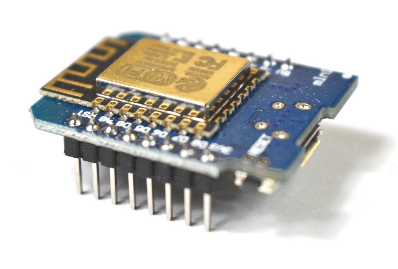
WeMos D1 Mini ESP8266 Arduino WiFi Board
“As an Amazon Associates Program member, clicking on links may result in Maker Portal receiving a small commission that helps support future projects.”
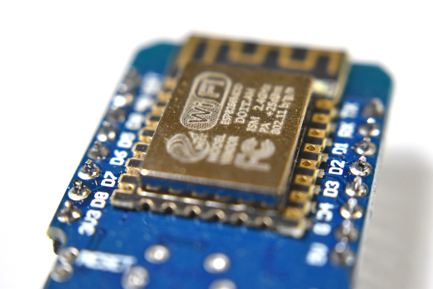
The WeMos D1 Mini is an inexpensive ESP8266-based WiFi board that is low-profile but just as powerful as any NodeMCU or ESP8266-based microcontroller. The D1 Mini is incredibly versatile because it is inexpensive, WiFi-enabled, and fully compatible with the Arduino platform. In this tutorial, the ESP8266 library and board manager will be introduced in order to get the D1 Mini acting as an Arduino board. Then, a simple web page will be introduced with the intention of harnessing the WiFi capabilities of the module. The D1 Mini will act as a web server, allowing any WiFi-connected device to interact with the board and control its pins wirelessly.

In the Package:
D1 Mini ESP8266 WiFi Module
Pins for Soldering
Product Specifications:
ESP8266 chipset
CH340 USB converter onboard (compatible with Raspberry Pi)
1 analog input
11 digital I/O
Works with many Arduino libraries
The first step toward interfacing the D1 Mini with the Arduino platform begins with downloading the ESP8266 board platform onto the Arduino IDE. This process is shown below:
In the Arduino IDE:
File -> Preferences

2. Add the following link to Additional Boards Managers URLs: https://arduino.esp8266.com/stable/package_esp8266com_index.json
3. Go to: Tools -> Board -> Boards Manager
4. Type in “esp8266” into the search
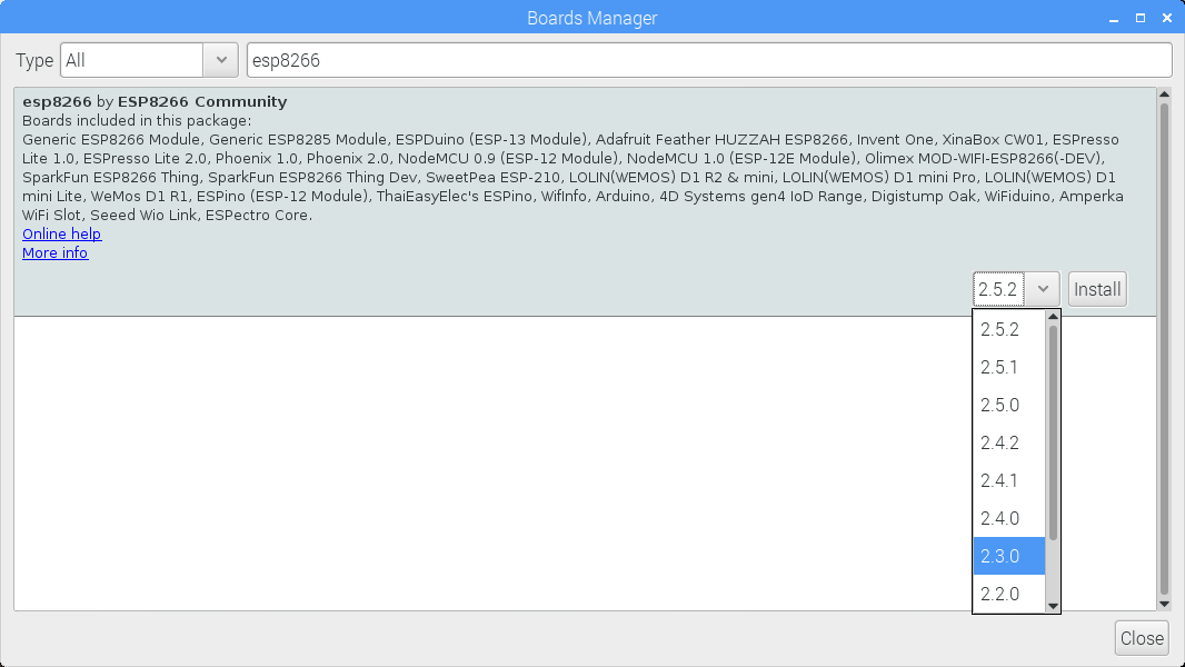
5. Install package entitled “esp8266 by ESP8266 Community” but ensure that version 2.3.0 or EARLIER is downloaded. There can be issues with more recent versions (not sure if it’s a Raspberry Pi issue or what).

6. Go to: Tools -> Board -> “WeMos D1 R2 & mini”
Ensure that the correct board specifications are selected similar to the reference above (Upload Speed, CPU Frequency, Flash Size). Once the steps above are completed, the D1 Mini board is ready to work with many of the Arduino examples.
As verification, upload the Blink sketch and observe that the D1 Mini onboard LED is blinking.
Note: If errors occur during upload, try uploading and immediately press the RESET button on the d1 mini board
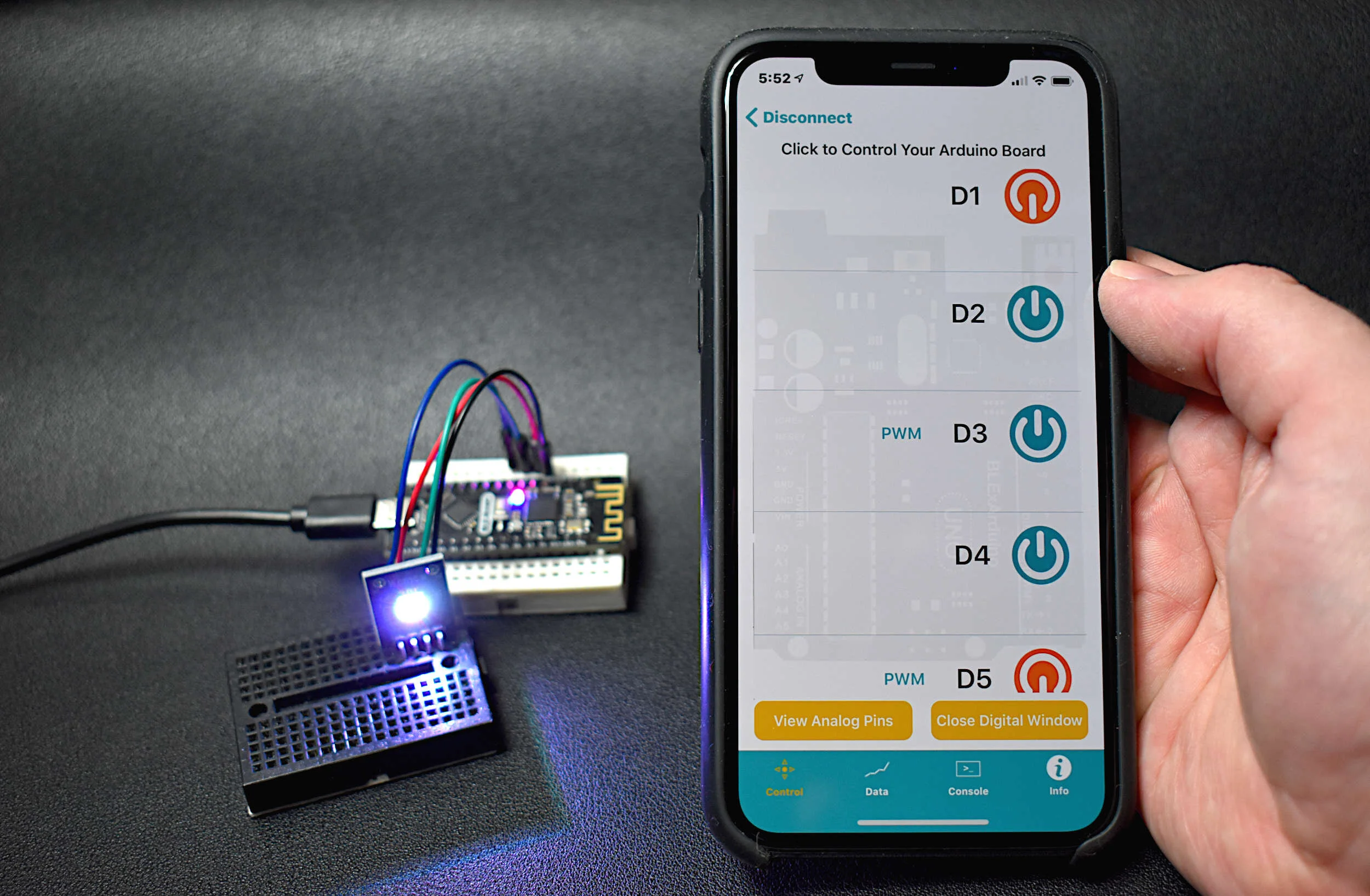
The D1 Mini has an ESP8266 at its core, which means that it can do many of the things an Arduino board can do (analog input, digital input, I2C, etc.), but it can also handle WiFi communication. The WiFi communication enables the D1 Mini to act as a local server and so much more. In this example, I will demonstrate the simplest implementation of the D1 Mini as a WiFi server by communicating between a device (smartphone, tablet, desktop) and the D1 Mini by communicating on a local host webpage.
The full code for controlling an LED using the D1 Mini is shown below:
#include <ESP8266WiFi.h>
#include <WiFiClient.h>
#include <ESP8266WebServer.h>
#include <ESP8266mDNS.h>

const char* ssid = "ssid";
const char* password = "password";
const int led = D1;

ESP8266WebServer server(80);

void handleRoot() {
  server.send(200, "text/plain", "hello from esp8266! (blinking LED)");
  int led_state = 0;
  for (int ii=0;ii<10;ii++){
    digitalWrite(led,led_state);
    led_state = !led_state;
    delay(100);
  }
}

void led_on(){
  server.send(200, "text/plain", "LED on");
  digitalWrite(led,HIGH);
}

void led_off(){
  server.send(200, "text/plain", "LED off");
  digitalWrite(led,LOW);
}

void setup(void){
  pinMode(led, OUTPUT);
  digitalWrite(led, 0);
  Serial.begin(115200);
  WiFi.begin(ssid, password);
  Serial.println("");

  // Wait for connection
  while (WiFi.status() != WL_CONNECTED) {
    delay(500);
    Serial.print(".");
  }
  Serial.println("");
  Serial.print("Connected to ");
  Serial.println(ssid);
  Serial.print("IP address: ");
  Serial.println(WiFi.localIP());

  server.on("/", handleRoot); // what happens in the root
  server.on("/on",led_on); // turn led on from webpage /on
  server.on("/off", led_off); // turn led off from webpage /off

  server.begin();
  Serial.println("HTTP server started");
}

void loop(void){
  server.handleClient();
}
The basic usage of the code above goes as follows:
Open the serial port in the Arduino IDE to discover the IP address of the server (something like: 171.20.0.5)
Type in the IP address on a smartphone, tablet, or desktop browser
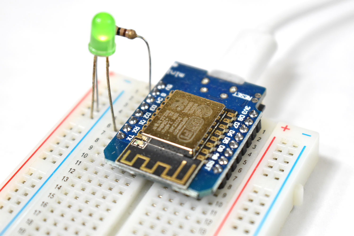
An LED should be connected to pin D1 and should blink 5 times and stay on
Navigate in the browser to: 171.20.0.5/off
The LED should be off now
Navigate in the browser to: 171.20.0.5/on
The LED should be on again
Obviously, this is a very rudimentary example of the capabilities of the D1 Mini and ESP8266 WiFi module, however, it is the basis for many smart home systems that rely on low-power devices to control peripherals such as: lights, fans, automatic blinds, and much more! Ideally, an app would handle this webpage navigation through button clicks, however, that application will be saved for the user.
In this tutorial, the D1 Mini ESP8266-based microcontroller and WiFi module was introduced. The D1 Mini is a sized-down NodeMCU board that boasts the ESP8266 again at its center. The D1 Mini is powerful because of its small profile and Arduino integration. As with the NodeMCU, the D1 Mini has a massive community of codes that makes developing WiFi-based projects easier than ever - all through the lens of the Arduino platform. This means that with a little Arduino background and some knowledge of web programming, users can create their own networks of web-based microcontrollers and devices.
See More in Arduino and WiFi: