SAMD21 M0 Mini Arduino Board
“As an Amazon Associates Program member, clicking on links may result in Maker Portal receiving a small commission that helps support future projects.”
The SAMD21 core is a 32-bit microcontroller that will likely replace the traditional ATmega328 (8-bit microcontroller) over time. The SAMD21 core boasts 48MHz clock speeds in contrast to the 20MHz ATmega boards, while also being fully-compatible with many of the capabilities of the Arduino platform. The SAMD21 boards incorporate a multitude of upgrades including: higher analog-to-digital resolution (12-bit over 10-bit), 10-bit digital-to-analog conversion (DAC), an on-board USB converter (compatible with Mac, Windows, and Linux), a two channel I2S interface, and much more! The SAMD21 is also compatible with many of the sensor libraries in Arduino that function with I2C communication, SPI communication, and other serial communications - which is essential for introducing the SAMD21 as an upgraded Arduino board used in conjunction with the myriad of examples and applications already available on the platform.
In this tutorial, I will introduce the SAMD21 M0 Mini, which is a variation of the Arduino Zero (SAMD21 48MHz). The SAMD21 board will be tested specifically in its speed and compatibility with several Arduino libraries. Particularly, the SAMD21 is the most powerful when harnessing its speed, but also in other areas such as analog to digital conversion.
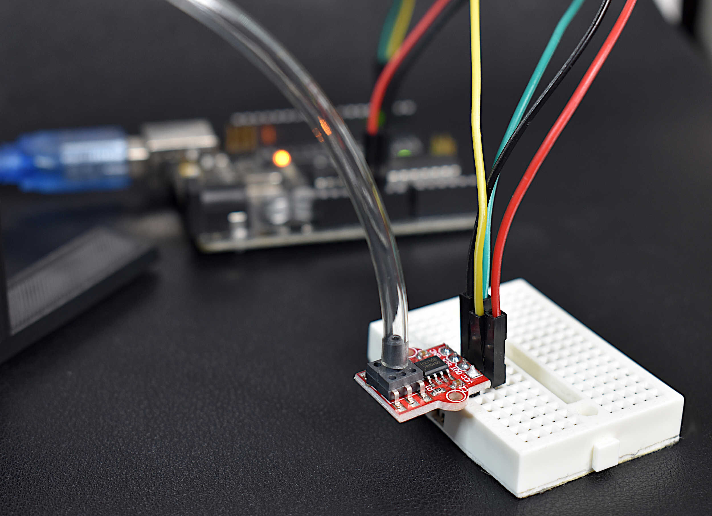
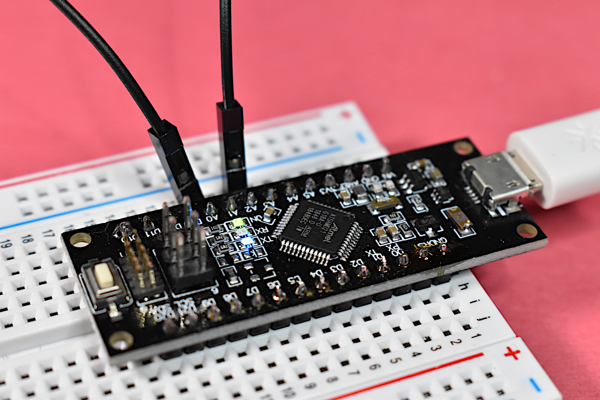
The SAMD21 M0 Mini board will be used as the primary component used here. I will also use LEDs, resistors, and jumper wires to demonstrate some of the capabilities of the SAMD21 chip. For reference, the pinout for the SAMD21 M0 Mini can be found here and the datasheet for the SAMD21 chip can be found here. Below is a list of affiliate or shop links of the components needed to carry out the tutorial here.

Included in Package:
SAMD21 M0 Mini 32-bit Microcontroller
Solder Pins
The SAMD21 core is a 32-bit microcontroller that will likely replace the traditional ATmega328 (8-bit microcontroller) over time. The SAMD21 core boasts 48MHz clock speeds in contrast to the 20MHz ATmega boards, while also being fully-compatible with many of the capabilities of the Arduino platform. The SAMD21 boards incorporate a multitude of upgrades including: higher analog-to-digital resolution (12-bit over 10-bit), 10-bit digital-to-analog conversion (DAC), an on-board USB converter (compatible with Mac, Windows, and Linux), a two channel I2S interface, and much more! The SAMD21 is also compatible with many of the sensor libraries in Arduino that function with I2C communication, SPI communication, and other serial communications - which is essential for introducing the SAMD21 as an upgraded Arduino board used in conjunction with the myriad of examples and applications already available on the platform.
Features of SAMD21 M0 Mini:
5V USB Power Input
3.3V, 180mA I/O Ratings
48MHz clock frequency
25 GPIO pins
12 PWM pins
6 12-bit analog I/O pins
1 Digital to Analog Converter (DAC)
32-bit ARM Cortex® M0+ core
I2C, SPI, I2S compatible
Widely compatible with the Arduino platform
The SAMD21 M0 Mini can be considered an Arduino Zero board, which also has a SAMD21 core at its center. Therefore, the needed board reference can be found in the Arduino IDE’s board manager without the need for any additional board manager URL download. The process for downloading the SAMD21 board list is shown below:
In the Arduino IDE:

1. Go to Tools -> Board -> Boards Manager

2. Type “SAMD” into the Boards Manager input and install the latest board package entitled: “Arduino SAMD Boards (32-bits ARM Cortex-Mo+) by Arduino”

3. Go to Tools-> Board -> Arduino/Genuino Zero (Native USB Port)

4. Ensure that the correct Port is selected, in this case: “Arduino/Genuino Zero (Native USB Port)”
As a verification, upload a sample Blink sketch with an external LED.
Some functions in Arduino are not directly importable into the SAMD21 board framework. For example, printing to the serial port with the SAMD21 needs to be changed from “Serial.print()” to “SerialUSB.print()” - which will print to the traditional Arduino serial port. This is because the SAMD21 has multiple serial ports, whereas the CH340 or CP2102 used by traditional Arduino boards convert the serial printing directly to the USB port. Therefore, a simple serial print in the SAMD21 framework should be done as follows:
// reading 12-bit analog data and printing to serial port for
// SAMD21 board
int analog_pin_1 = A0;
int analog_pin_2 = A1;
void setup() {
  SerialUSB.begin(115200); // initialize USB serial port
  analogReadResolution(12); // set ADC to 12-bit
  pinMode(analog_pin_1,INPUT); // analog 1
  pinMode(analog_pin_2,INPUT); // analog 2
}

// the loop function runs over and over again forever
void loop() {
  // print to USB serial port for each analog channel, comma separated
  SerialUSB.print(analogRead(analog_pin_1));
  SerialUSB.print(",");
  SerialUSB.println(analogRead(analog_pin_2));
  delay(1000);
}
There are two important changes in comparison to the ATmega boards, first: the “SerialUSB.print()” is used to print to the serial port visible to the user, and second: the analog read resolution change from 10-bit to 12-bit. The readings therefore range from 0-4095, correlating to voltages from 0-3.3V. This can be tested by inserting the 3.3V pin into one of the analog pins, which subsequently reads 4095. This means that our ADC resolution is roughly 0.8 mV/bit, which is more than six times higher resolution than the 8-bit Arduino boards.
One of the more interesting advantages to the SAMD21 is its digital to analog converter (DAC). Much like the Arduino Due, which also has a 10-bit DAC, the SAMD21 is capable of outputting 10-bits of analog data on its A0 pin. This is done by setting the analogWriteResolution() to 10-bits and subsequently writing to the A0 pin. The A0 pin is the only pin available for analog writing - however, if other pins are written-to using the analogWrite() function, then they will either register HIGH/LOW or use PWM signals depending on their capabilities.
The code below is an implementation of the DAC and subsequent reading on the ADC. The code does the following:
Outputs a sine wave to the 10-bit DAC
Reads from the 12-bit ADC
Prints the DAC output and the values read from the ADC
// reading 10-bit DAC data on the SAMD21's 12-bit ADC

int analog_out = A0;
int analog_in = A2;

float dac_iter = 0.0;

void setup() {
  SerialUSB.begin(115200); // initialize USB serial port
  analogWriteResolution(10); // set DAC to 10-bit
  analogReadResolution(12); // set ADC to 12-bit
}

void loop() {
  dac_iter+=0.01; // step through for sine wave
  analogWrite(analog_out,int((511.5*sin(2*PI*dac_iter))+511.5)); //DAC sine
  // DAC sine wave for plotting comparison
  float a_out = (((511.5*sin(2*PI*dac_iter))+511.5)/1023.0)*3.3;

  float a_read = (analogRead(analog_in)/4095.0)*3.3; // ADC 12-bit reading
  // plot for serial plotter or just viewing in serial monitor
  SerialUSB.print("DAC: ");
  SerialUSB.print(a_out);
  SerialUSB.print(", ADC: ");
  SerialUSB.println(a_read);
  delay(10); // as needed
}
For the code above to work properly, pin A0 must be wired directly to pin A2. The resulting output onto the serial plotter should look as follows:
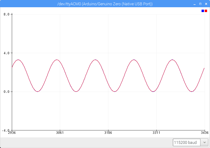
Example output of the SAMD21 analog-to-digital converter (ADC) reading values outputted by the digital-to-analog converter (DAC). The red represents the ADC and the blue represents the DAC.
The SAMD21 M0 Mini board is a great upgrade to the classic 8-bit Arduino boards and an inexpensive update to the DIY microcontroller world. The SAMD21, as was demonstrated in this tutorial, is compatible with the Arduino platform and capable of carrying out many of the same tasks as the traditional Arduino boards, and with only minor variations in programming. This tutorial was intended as an introduction to the SAMD21 M0 Mini board and an easy cross-over from ATmega 8-bit boards to a faster and higher performing SAMD21 chip. The SAMD21 is able to write to the serial port without any external USB adapter (in contrast to the ATmega boards), it boasts a 12-bit ADC, 10-bit DAC, and runs at 3.3V. This is only the first piece of a series dedicated to the introduction of the SAMD21 board, and serves as an easing from ATmega to SAMD21. For the next entry, I will focus on I2C communication and interfacing with several sensors. There will likely be a tutorial dedicated to the comparisons between ATmega328 and the SAMD21 chip to benchmark efficiency, compatibility, and function.

See More in Arduino and Microcontrollers: