

“As an Amazon Associates Program member, clicking on links may result in Maker Portal receiving a small commission that helps support future projects.”
This is a quick and fun tutorial on how to create an inexpensive laser pointer cat toy using DIY parts either found around the maker space or bought for other projects. It is an inexpensive and fun project that almost any maker or engineer could put together in a matter of minutes. It uses a cheap laser that can be found in many electronics kits (I’m using a red, 650 nm), a small button, and a 3.7V LiPo battery.
The primary parts needed for this project can be found on Amazon and, of course, in many labs and maker spaces in the form of spare parts or harvested components. I have listed some parts on Amazon that will work nicely with the project:
The simplest design of the laser toy is to press a button and the laser turns on. This will allow the owner to press the button to turn on the laser and, with the LiPo batteries above, recharge the battery once the battery dies after some time. This flexibility prevents the owner from having to buy new batteries for the pointer all the time, and also allows the owner to tweak the device to their own liking (interchange different laser colors, use smaller batteries, attach the laser to a motor, etc.). The wiring for this project is shown below.
Wiring the Push Button to Control the Laser
All we are doing above is cutting off the hot connection to the laser diode and wiring it to the push button. Make sure to wire the push button such that when the button is not pressed, the laser is off. When the button is pushed, the circuit will be completed and the laser will be active.
Below is an image of the soldered laser to the push button, with the appropriate wires plugged into the LiPo battery:

Below is a photo of the button being pushed and the laser shining:

It’s not the prettiest setup, but it’s easy and modular! Also, any maker with experience in 3D printing could build a case for the laser pointer/Lipo/push button and really make a realizable product.
With the press of a button the laser should work! It’s quite bright, so be sure not to point it directly at any living thing’s eyes.
This is a simple and fun project that anyone can carry-out with the proper tools and minimal knowledge of electronics. It teaches the user how to take parts and build a real-world technology (human-controlled laser). It also utilizes soldering skills, wiring skills, the basics of buttons in electronics, and how to use LiPo batteries to create a rechargeable product. Most importantly, it produces an end product that someone (a cat or other animal) can enjoy.

See More in DIY:

The MakerBLE is introduced as a miniature breakout board variation of the nRF52840 Bluetooth Low Energy (BLE) Arduino board, which is capable of communicating with smartphnoes and carrying out many of the capabilities of other wirelessly-enabled microcontrollers. The MakerBLE is also compatible with our iOS app, BLExAR, and allows users to collect data, send commands, and control pins remotely from a smartphone. In this tutorial, the MakerBLE will be introduced and its capabilities will be explored from the perspective of the Arduino. This will also be the first in a series of entries geared toward low-power, BLE-enabled, tiny microcontroller projects; whether they involve remote control, data collection from sensors (I2C, SPI, UART), message transfers, BLE peripheral/central communication, or general electronics testing.
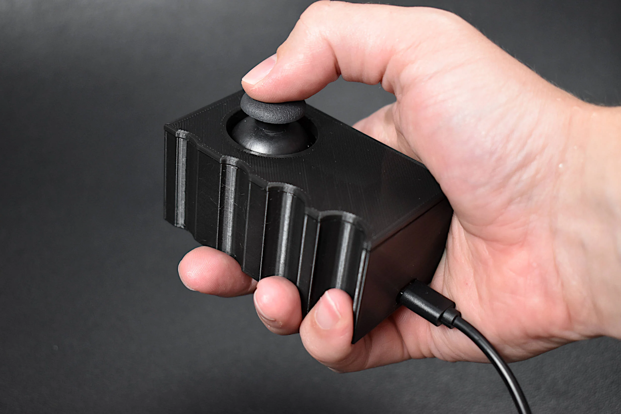
A vibration motor and joystick are used to create a haptic feedback device using the Arduino platform. As a response to specific changes in joystick position, we prescribe vibration motor actions corresponding to the movement of the joystick. This allows for creation of vibrational feedback similar to that used in video games and virtual reality systems. The goal of this tutorial is to introduce users to haptic technology that can immerse users into the digital world using physical feedback mechanisms, such as vibration. Different tunings of the vibration motor can provide users with instructions based on their input, which makes this type of application useful for enhancing digital media, as referenced above, or situations such as visually impaired navigation, feedback in auditory-restricted environments, and delivering quiet notifications to users. Haptics can be incredibly useful in emulating the real world and immersing users into scenarios that may otherwise be dangerous or difficult to experience. Vibrational haptic feedback is just one of a series of haptic mechanisms, and this tutorial was just a simple entry into a wide ranging and evolving field of human computer interaction.
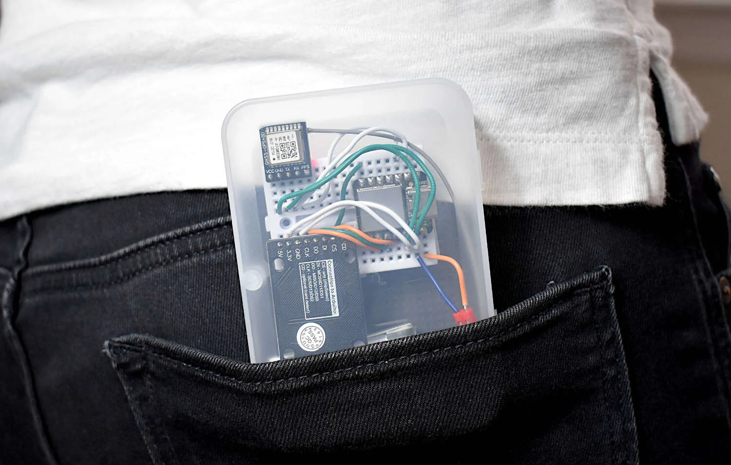
In the past, we explored the NEO-6M GPS module with Arduino through a few of our tutorials (see: "Comparing iPhone GPS Against NEO-6M with Arduino" and "Arduino GPS Tracker"). In this tutorial, we wanted to push the size limits of the portable GPS tracker by using a mini GPS module called the ATGM336H. The result is a pocket-sized GPS tracker with the low-profile by pairing the ATGM336H module with an Arduino Xiao microcontroller, SD Card Module, and 3.7V LiPo Battery. The prototype developed here will be an autonomous tracker that will record latitude/longitude at roughly 1-10 points per second (1Hz - 10Hz) and needs no external components to track geolocation. The prototype can fit in a users pocket and can track for several hours. We will also present a Python program that will plot the geolocation data points that the user can use to view the route tracked by the Arduino GPS datalogger system. The Python analysis demonstrates how well the ATGM336H GPS module and antenna are able to replicate the walking path of a human with great resolution and accuracy.

In this tutorial, a 1.54 inch e-Paper module is wired to a BLE-Nano Arduino board to communicates via SPI and display text in real time over Bluetooth. The e-Paper module here can be powered via 3.3V or 5.0V, requires very low power when refreshing (2mA-8mA), and can be completely powered off while retaining its text. An Android smartphone and the BLExAR app will be used to print text on the e-Paper display in real time, demonstrating the capabilities of electronic paper technology.
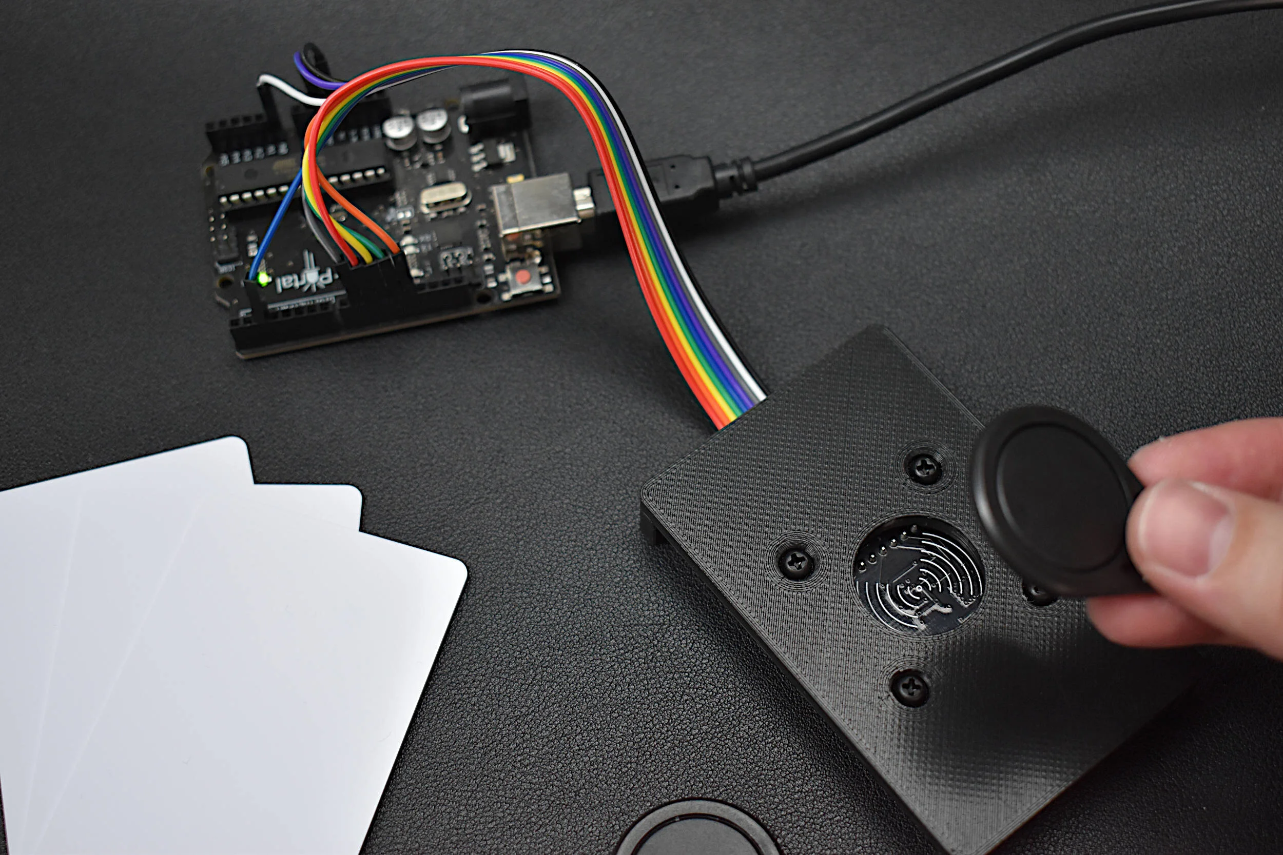
Radio Frequency Identification, or RFID, is a widely used technology developed for storing and retriving information in radio frequency-enabled devices. Most often, RFID systems consist of one or multiple RF tags, an RF reader, and a database. In this tutorial series, passive, high frequency (13.56 MHz) RFID tags are the focus, as they are very compact, inexpensive, and require no external battery power. Using an Arduino board, a common RFID reader (MFRC522), and a few RFID tags/cards, we will be exploring methods for reading and writing RFID information in an attempt to understand the how RFID communication works and the limits of the technology.
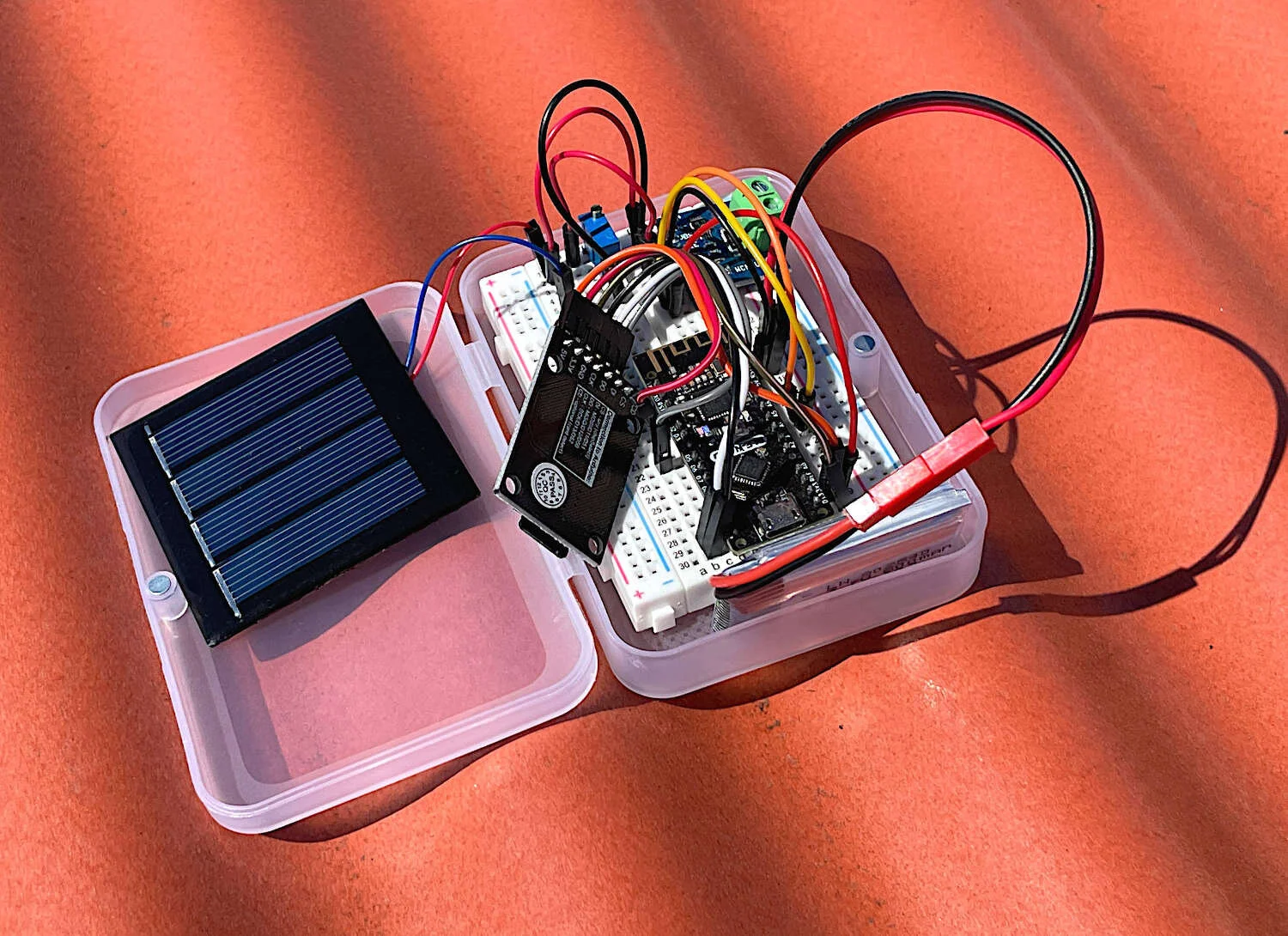
In this tutorial, the aim is to characterize a solar panel by varying the load at (near) peak solar insolation to identify the panel's nominal values such as open-circuit voltage, short-circuit current, max power voltage and current, and max power output. These values help users understand the expectations from a photovoltaic array and how their power needs may be met with a given PV system. An Arduino board will be used to log the current and voltage values outputted from a small solar panel. The current and voltage are measured using a 16-bit analog-to-digital converter power module, the INA226, which will allow us to track the power outputted from the photovoltaic panel. A potentiometer acting as a rheostat will serve as the varying load on the system, which will be used to identify the peak power points of the system. Finally, analyses will be conducted in Python 3, which will allow us to identify the peak power region and also the total power outputted over a duration of 24 hours.
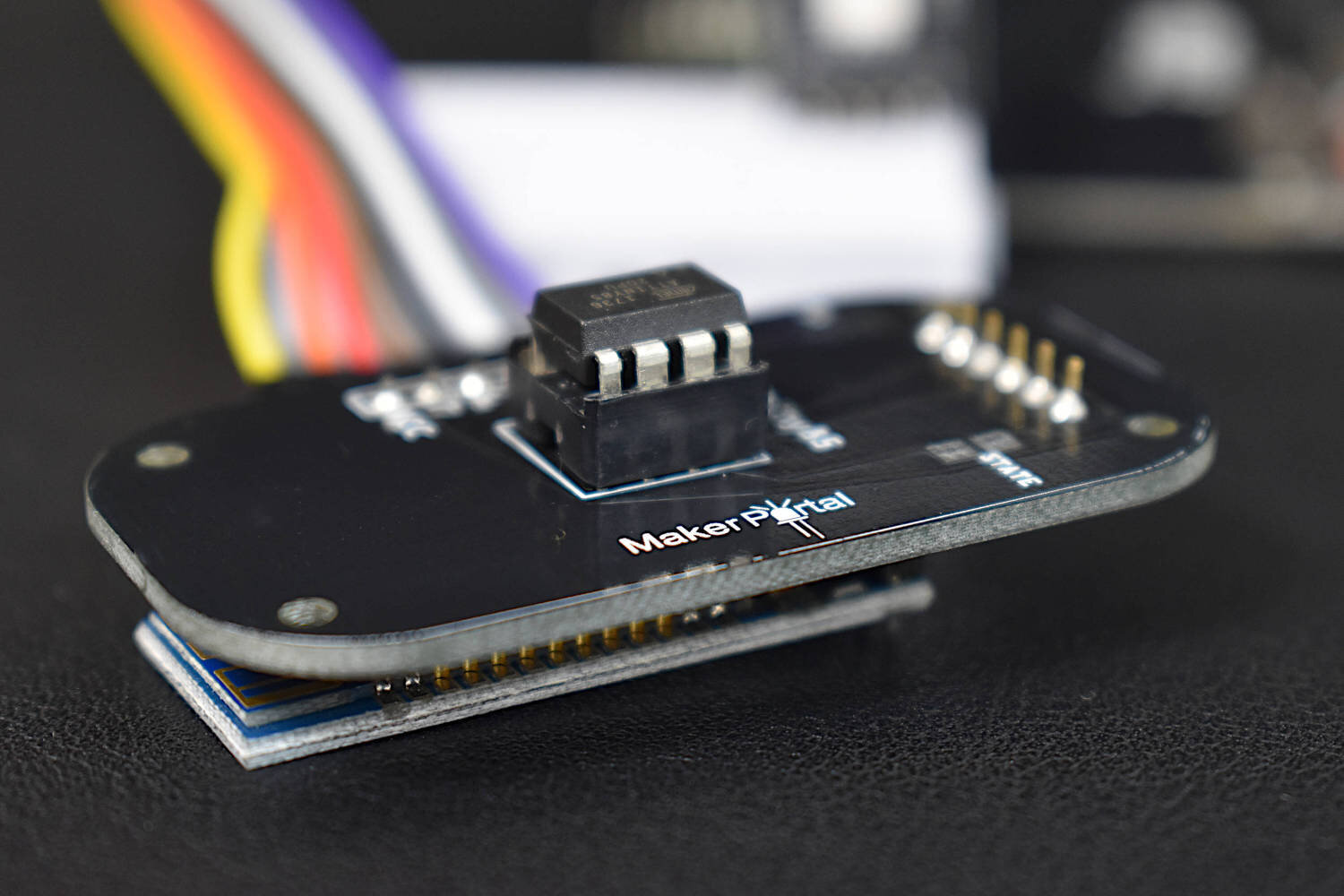
The TinyBlueX is a Bluetooth Low Energy-enabled microcontroller module that combines an ATtiny85 microcontroller and CC254x Bluetooth Low Energy chip. The TinyBlueX is compatible with the Arduino platform (IDE) and the BLExAR iOS Arduino app. The TinyBlueX is very low power and has a low profile, which makes it great for very low power internet of things (IoT) applications with analog and digital sensors. The TinyBlueX can read sensors and transmit the data back to an iOS device, while also being able to read iOS commands and control LEDs, indicators, and motors. Pins 2,3,7 are available on the ATtiny85 aboard the TinyBlueX, allowing users to control/read up to 3 different devices or sensors. In this tutorial series, the TinyBlueX will be explored by instructing users on how to upload code to the module, how to control LEDs, and how to send data back to an iOS device using the BLExAR app.
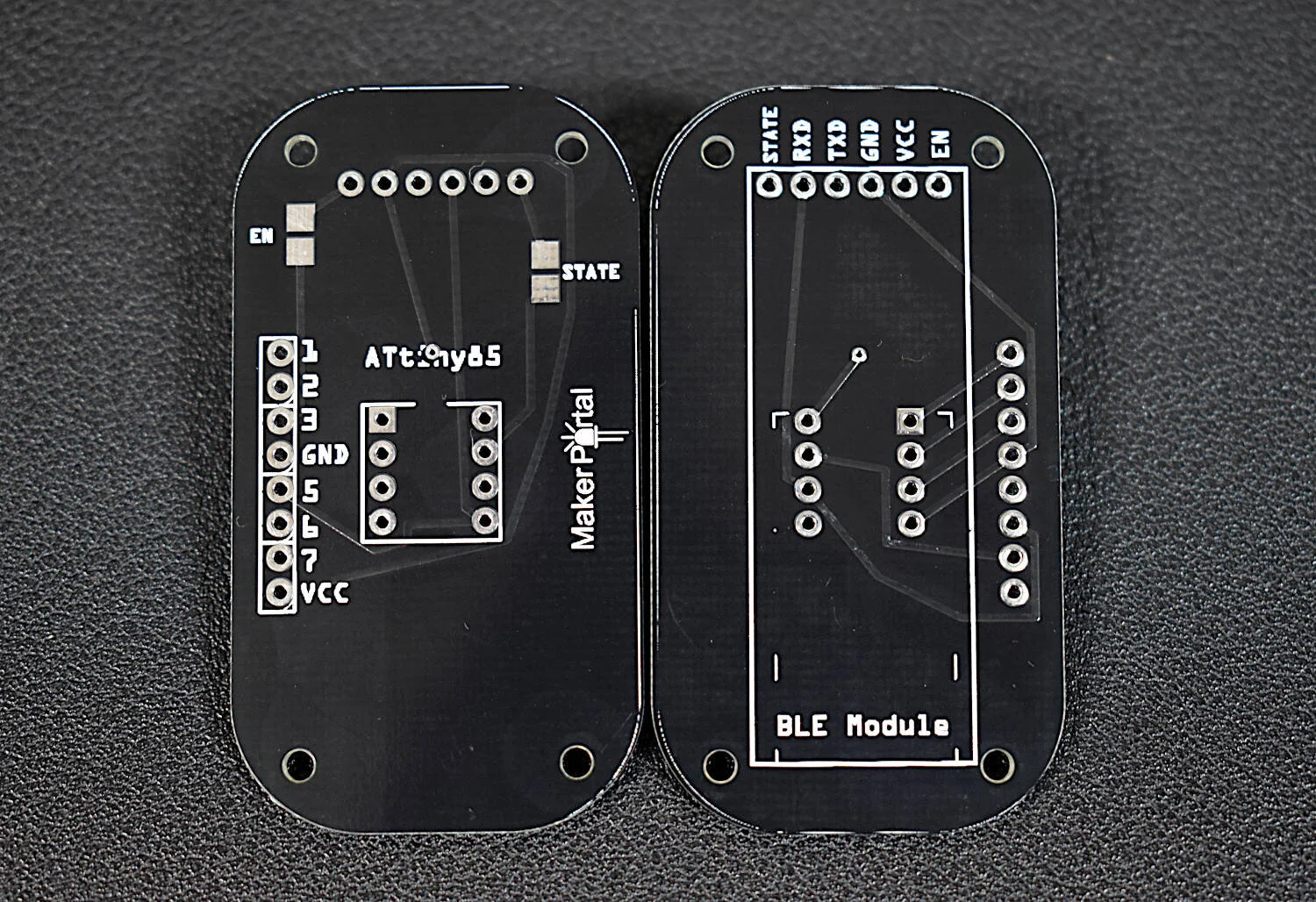
The printed circuit board (PCB) is at the center of nearly all electronics products in the 20th century. PCBs originally consisted of wires placed along paths connecting a series of components on a rigid board — these were deemed printed wiring boards. Eventually, the printed wiring board morphed into the circuit boards with conducting strips etched into multi-layer boards that we see on PCBs today. The PCB industry is associated with nearly $1 trillion in sales of electronics each year [read more at: "Printed circuit board industry"]. Thus, it is important for engineers to know at least the basics of PCB design, even if the manufacturing is outsourced to companies. In this tutorial, we will introduce the design of a simple PCB and the process required to get the PCB manufactured by a company called NextPCB. Their process is simple and easy, and even allows the engineer to view their design on their online gerber file viewer.

For this project, we will be comparing the WaWiCo sensor with a conventional hall-effect mechanical flow meter. The WaWiCo sensor introduces a novel method for water metering, with non-invasive acoustic analysis. The benefit of the WaWiCo method is evident during the mechanical flow meter analysis, where we need to match pipe diameters and fittings and ensure that the flow terminates at a point. Otherwise, mechanical meters require cutting in piping — which is not an option for many users. Using a Raspberry Pi computer and a WaWiCo USB water meter kit, the frequency content of water flow for a given pipe is analyzed. Additionally, this frequency response will be used to correlate to the flow rate (in L/s) approximated by the mechanical flow meter. This brings us one step closer to being able to non-invasively measure water flow using the WaWiCo method.

The Raspberry Pi Pico is a microcontroller designed by the Raspberry Pi foundation. The Pico is a groundbreaking board that is meant to use MicroPython in its native micro USB port. The RP2040 is the microcontroller chip at the center of the Pico, which has a dual-core Arm Cortex M0+ processor, capable of clocking at 133 MHz, which is much faster than many of the Arduino boards currently on the market. The Pico has GPIO pins and interfaces such as: SPI, UART, I2C, PWM, and a 12-bit analog-to-digital converter (ADC). This Raspberry Pi Pico comes with the Pico microcontroller, 2x 20-pin solder header, and a micro-USB cable.
Included with the Raspberry Pi Pico Microcontroller:
1x Raspberry Pi Pico Board
2x 20-pin Headers
1x Black 0.5m Micro USB Cable
Features of the Raspberry Pi Pico:
1.8V - 5.5V Input Voltage
21 mm × 51 mm Board Geometry
RP2040 microcontroller
Dual-core Arm Cortex-M0+ processor (Clock Speed up to 133 MHz)
264KB on-chip SRAM, 2MB on-board QSPI Flash
26x GPIO pins (3x 12-bit Analog Inputs)
2x UART, 2x SPI, 2x I2C, 16x PWM
1x USB 1.1 controller and PHY, with host and device support
8x Programmable I/O (PIO) state machines for custom peripheral support
Operating temperature -20°C to +85°C
Low-power sleep and dormant modes
Onboard Temperature sensor
Accelerated integer and floating-point libraries on-chip

The MLX90640 is a 768-pixel (32 x 24), low-cost thermal camera. It uses an array of infrared detectors (and filters) to detect the radiation given off by nearby objects by taking advantage of Planck’s radiation law. The MLX90640 is most notable because of its easy-to-use Python libraries that allow it to be read by Raspberry Pi computers. The MLX90640 can be used to map and record high-resolution temperature maps at refresh rates of up to 64 times per second (64Hz).
NOTE: There are two versions here, 1. an unsoldered board that needs to be soldered to be wired properly; and 2. a version that has a breakout connector that can be connected directly to a Raspberry Pi via the JST Dupont connector.
Included in the MLX90640 Thermal Camera Sensor Package:
1x MLX90640 Thermal Camera (32 x 24 Pixels, 55° x 35°)
Pin Header
5x Male-to-Female Jumper Wires (or JST Dupont connector for breakout version)
Features of the MLX90640 Thermal Camera:
Object Detection Temperatures: -40°C to +300°C
3V-6V Supply Voltage
20mA Average Current Consumption
32 x 24 Resolution, 768 Pixels in Total
55° x 35° Field of View
I²C Communication (Address: 0x33)
Ambient Temperature Operating Range: -40°C to +85°C
Raspberry Pi and Arduino Compatible
JST Dupont Breakout Pinouts:
Black for GND
Red for V+
Blue for SDA
Yellow for SCL
MLX90640 Datasheet
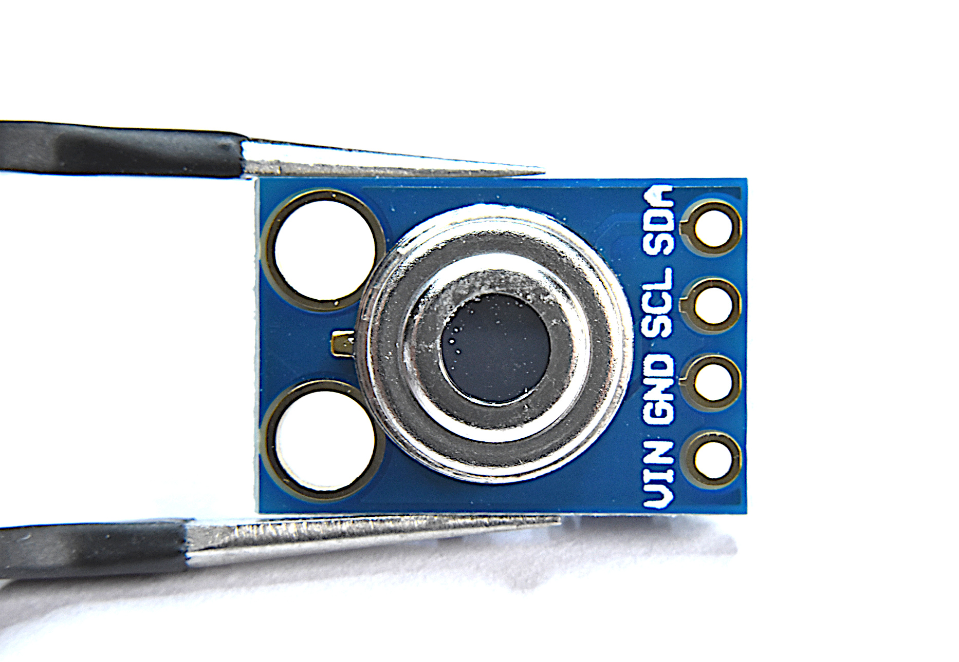
What comes in this package:
MLX90614 IR sensor
MLX90614 Specs:
3-5V Operating Voltage
-70 °C to 380 °C Object Temperature Measurement Range
0.5 °C Accuracy (0-50 °C)
0.02 °C Measurement Resolution’
At 35° Viewing Angle, Temperature is half the 0° Angle Value
I2C Wiring works with Arduino and Raspberry Pi
Full Datasheet download here

Included in Package:
1x NEO-6M GPS Module (GY-GPS6MV2)
1x Ceramic Antenna
1x 4-Pin Solder Pin Header
Module Description:
Power Supply: 3V-5V
EEPROM
LED Indicator
Backup battery
Baud Rate: 9600
Mounting Holes: 3mm
Module Dimensions: 23mm x 30mm
Antenna Dimensions: 25mm x 25mm
Antenna Cable Length: 50mm
Arduino UART Compatible
The MakerBLE is introduced as a miniature breakout board variation of the nRF52840 Bluetooth Low Energy (BLE) Arduino board, which is capable of communicating with smartphnoes and carrying out many of the capabilities of other wirelessly-enabled microcontrollers. The MakerBLE is also compatible with our iOS app, BLExAR, and allows users to collect data, send commands, and control pins remotely from a smartphone. In this tutorial, the MakerBLE will be introduced and its capabilities will be explored from the perspective of the Arduino. This will also be the first in a series of entries geared toward low-power, BLE-enabled, tiny microcontroller projects; whether they involve remote control, data collection from sensors (I2C, SPI, UART), message transfers, BLE peripheral/central communication, or general electronics testing.
A vibration motor and joystick are used to create a haptic feedback device using the Arduino platform. As a response to specific changes in joystick position, we prescribe vibration motor actions corresponding to the movement of the joystick. This allows for creation of vibrational feedback similar to that used in video games and virtual reality systems. The goal of this tutorial is to introduce users to haptic technology that can immerse users into the digital world using physical feedback mechanisms, such as vibration. Different tunings of the vibration motor can provide users with instructions based on their input, which makes this type of application useful for enhancing digital media, as referenced above, or situations such as visually impaired navigation, feedback in auditory-restricted environments, and delivering quiet notifications to users. Haptics can be incredibly useful in emulating the real world and immersing users into scenarios that may otherwise be dangerous or difficult to experience. Vibrational haptic feedback is just one of a series of haptic mechanisms, and this tutorial was just a simple entry into a wide ranging and evolving field of human computer interaction.
In this tutorial, a 1.54 inch e-Paper module is wired to a BLE-Nano Arduino board to communicates via SPI and display text in real time over Bluetooth. The e-Paper module here can be powered via 3.3V or 5.0V, requires very low power when refreshing (2mA-8mA), and can be completely powered off while retaining its text. An Android smartphone and the BLExAR app will be used to print text on the e-Paper display in real time, demonstrating the capabilities of electronic paper technology.

This is the second entry into the tutorial series centered around the MakerBLE Arduino board. Using the BLExAR iOS app again, we are able to monitor the incoming data from the MakerBLE board, plot the values, and save them to a comma-separated value (CSV) file. The data being sent is read from a BMP280 sensor over the I2C port by the MakerBLE board. Temperature, atmospheric pressure, and approximate altitude were all sent over the BLE connection with an iPhone.