Arduino Interrupts with PIR Motion Sensor

“As an Amazon Associates Program member, clicking on links may result in Maker Portal receiving a small commission that helps support future projects.”

Included in the Mini PIR Motion Sensor Package:
1x PIR mini motion sensor
Features of PIR mini motion sensor:
detects infrared radiation, which is often used to monitor human motion for home automation purposes.
Features of the Mini PIR Motion Sensor:
Voltage input: 2.7-5V
Time between successive trips: 2s
Physical Detection Range:
-45 to +45 degrees from central point
3m - 5m
Miniature Profile: 12mm x 25 mm
In this tutorial, the basics of Arduino’s hardware interrupt will be explored through the use of a passive infrared (PIR) sensor. The passive infrared sensors used here operate at voltages from 2.7V - 5V and use very little energy when operating in the non-tripped state. The PIR sensor is ultimately tripped by an infrared source, typically human body heat (or another animal with similar radiative emission). When the PIR sensor is tripped it sends a HIGH signal to its OUT pin, which will be read by the Arduino’s interrupt pin (pin 2 or 3 on the Uno board). This process seems trivial, but when done correctly can save massive amounts of energy when dealing with battery-powered systems, as in home automation.
This is a fairly simple demonstration of a crucial concept using Arduino, therefore, few parts will be needed. Of course, the concepts used here can be extrapolated onto more complex problems such as home automation, low energy sensors, and much more. The three main components needed for demonstrating interrupts in Arduino are:
PIR Mini Motion Sensor - $5.00 [Our Store]
Arduino Uno board - $11.00 [Our Store]
LED - $12.999 (450 pcs) [Amazon]
1 kOhm Resistor - $10.99 (1280 pcs) [Amazon]
The wiring diagram for the PIR sensor and LED to the Arduino board is shown below:

It may not be clear, but the PIR sensor pins are (from left to right):

1. VCC
2. OUT
3. GND
A full-length overview of the Arduino interrupt library can be found at this link. The interrupt library has many features and works on different pins and even has subtle differences in functionality, depending on the board being used (Uno, Due, Mega, etc.). This tutorial focuses on the ATmega328P boards, particularly the Uno board. The methods introduced should work on any ATmega328-based board, but have not been tested at length on each.
When handling interrupts on Arduino, there are three important things to that define the interrupt:
The pin used for interrupting
The function used when interrupted
The mode used for interruption
This is even clearer when we look at the functional call of an interrupt, called: “attachInterrupt()”:
attachInterrupt(interrupt_pin, interrupt_routine, interrupt_mode)
The “interrupt_pin” is not to be confused with the actual pin being used. For the Uno board (ATmega328P) there are two interrupts: one on pin 2 and one on pin 3. However, in the “attachInterrupt()” routine, since there are only two interrupts, the “interrupt_pin” must be either 0 (pin 2) or 1 (pin 3). Another way to more easily write this is:
attachInterrupt(digitalPinToInterrupt(pir_pin), interrupt_routine, interrupt_mode)
where Arduino has created a function which handles the PIR input pin and converts it to the board’s respective interrupt number.
Next, we can analyze the “interrupt_routine” and what it means in the context of our PIR sensor. If we write our full Arduino code out in the simplest form we have the following:
const byte led_pin = 8;
const byte interrupt_pin = 2;
volatile byte state = LOW;

void setup() {
  Serial.begin(9600);
  pinMode(led_pin,OUTPUT);
  attachInterrupt(digitalPinToInterrupt(interrupt_pin),interrupt_routine,RISING);
}

void loop() {
  if (state==HIGH){
    digitalWrite(led_pin,HIGH);
    delay(500);

  }
  if (state==HIGH) {
    Serial.println("low");
    state = LOW;
    digitalWrite(led_pin,LOW);
  }
}

void interrupt_routine(){
  state = HIGH;
  Serial.println("interrupt");
}
Upon inspection of the code above, we can see that not much changes between a standard PIR tripping code, except we don’t read the digital pin each loop, instead, we are waiting for the interrupt to occur, which lets the loop know to turn on the LED.
The “interrupt_routine” is a special function that is carried out each time the pin is interrupted. The function requires global variables if they are to be changed each loop. For example, in the code above, the interrupt routine simply changes the value of the variable “state” to HIGH, and prints out the word “interrupt.” This change of state is used to turn on the LED in the repeating loop in the Arduino program. Then, after raising the LED, it is subsequently turned off after some amount of time.
Note: the function "interrupt_routine" must only be used to change state variables or complete short tasks. The main loop should handle any timing tasks or longer processing tasks.
The last variable in the interrupt is the “interrupt_mode” which controls how the interrupt is tripped. There are four types of modes for interrupts on the Uno board:
RISING: when the pin goes from LOW to HIGH, the interrupt is triggered
FALLING: when the pin goes from HIGH to low, the interrupt is triggered
LOW: when the pin is LOW, the interrupt is triggered
CHANGE: when the pin changes from either LOW to HIGH or HIGH to LOW, the interrupt is triggered
For the PIR sensor, it registers LOW when no motion is detected, which is why we are interested in LOW to HIGH changes, namely RISING. This is why in the code above, RISING has been chosen as the interrupt mode.
Perhaps the most useful advantage of the interrupt is its ability to function with very little needed from the processor. The interrupt is based on an external, hardware-based process, which takes a lot of the load off the Arduino processor. This has huge implications on the power consumption side of using microcontrollers. This method is also a huge advantage for wireless applications that need to conserve power. As such, using an Arduino low power library with an interrupt can save a huge amount of power. Just how much power? That will be explored in this section.
The RocketScream low power library (download here and place it in your Arduino Libraries folder) will be used to lower the consumption on the Arduino board to milli-amps. The library is compatible with Arduino’s interrupt methods, so we will be able to run the low power mode to sleep forever until the external PIR sensor interrupts the sleep. Then, we can carry out tasks like logging the time of the motion, and finally go back to sleep and prepare for the next PIR tripping.
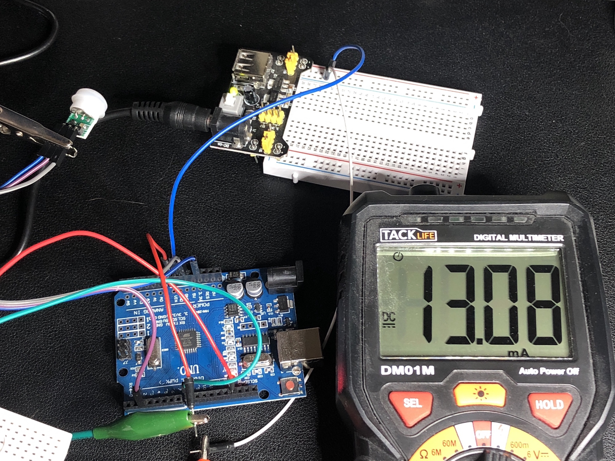
Without low power libraries, the current consumption of the code above is roughly 13 mA during the idle period and 15 mA during the interrupted routine. Upon implementation of the LowPower library, the current consumption is minimized down to 4 mA, which is a 70% reduction in power consumption. Snapshots of both of these are shown below:
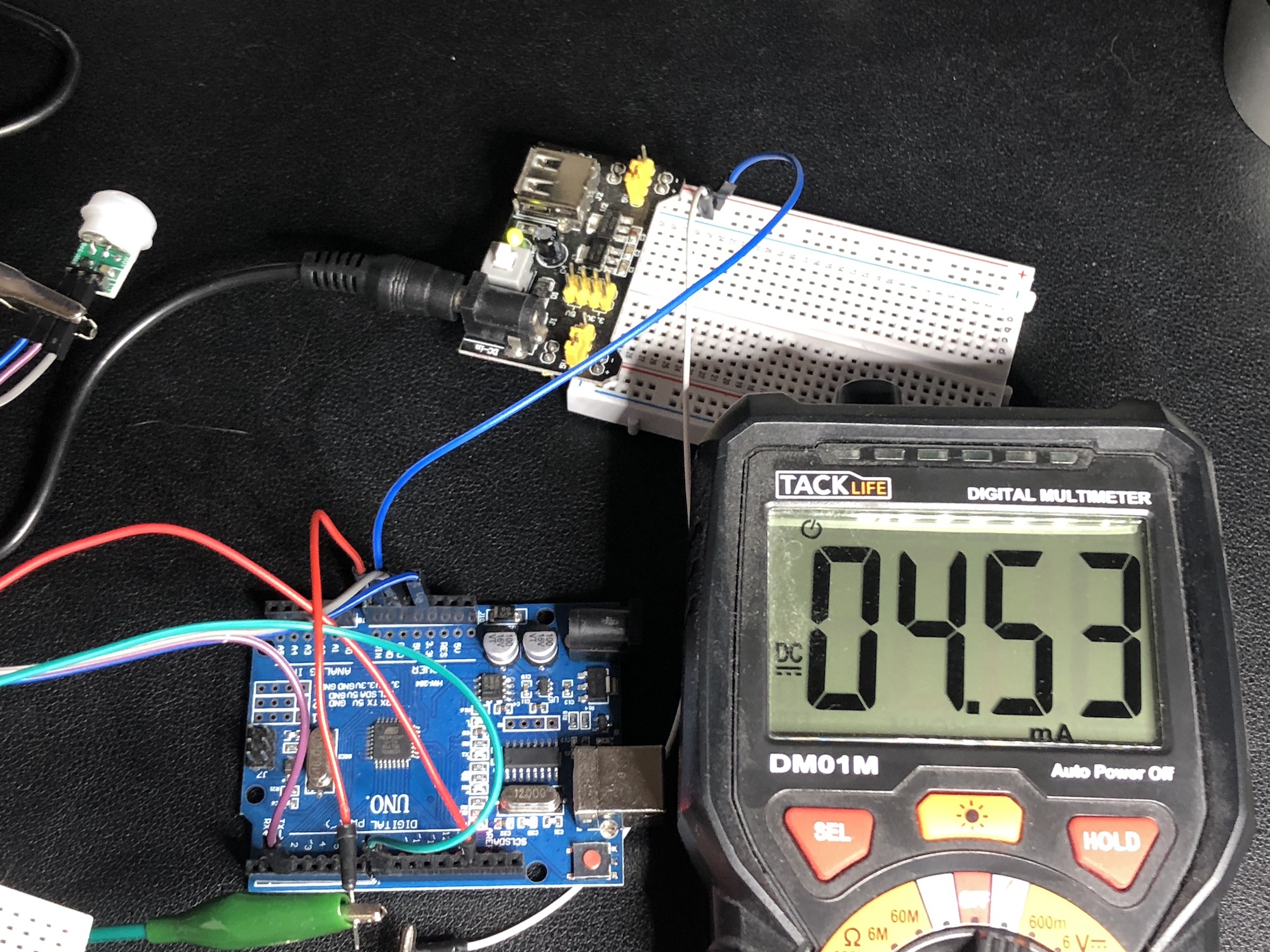
The ability to keep the Arduino asleep at 4 mA means that we can run the program for 3-4 times longer than without the library, and it’s even more efficient if we think about the consumption without interrupts. The code for the interrupt with the LowPower library is given below:
#include <LowPower.h>

const byte led_pin = 8;
const byte interrupt_pin = 2;
volatile byte state = LOW;

void setup() {
  Serial.begin(9600);
  pinMode(led_pin,OUTPUT);
}

void loop() {
  // the interrupt must be attached each loop
  attachInterrupt(digitalPinToInterrupt(interrupt_pin),interrupt_routine,RISING);
  LowPower.powerDown(SLEEP_FOREVER,ADC_OFF,BOD_OFF); // sleep until interrupt
  detachInterrupt(digitalPinToInterrupt(interrupt_pin)); // remove interrupt
  // the usual wake routine that turns on the LED
  if (state==HIGH){
    digitalWrite(led_pin,HIGH);
    delay(500);
  }
  if (state==HIGH){
    state = LOW;
    digitalWrite(led_pin,LOW);
  }
}

void interrupt_routine(){
  state = HIGH;
}
If one were to remove some of the bulky and unnecessary components on the Arduino board, or even just start with the ATmega328P board and build a bare bones Arduino board, this current consumption value can be minimized down to the micro-amps region, which can last for months on the right LiPo battery setup.
Interrupts are incredibly important for performing quick tasks where constant monitoring of digital pins may be unnecessary. Interrupts are also essential for saving power and minimizing the role of the microcontroller. Interrupts can be found in home automation applications, especially in motion detection, as introduced above (with passive infrared detectors). A low power library was also introduced for minimizing the power consumed between trips of the PIR sensor - this helps to minimize the role of the Arduino chip and allow the sensor to determine when the Arduino board is active, ultimately saving 70% on power consumption.
See More in Arduino: