Calibration of an Inertial Measurement Unit (IMU) with Raspberry Pi - Part I
Inertial measurement units (IMUs) can consist of a single sensor or collection of sensors that capture data meant to measure inertial movements in a given reference frame. Acceleration, speed of rotation, and magnetic field strength are examples of sensors contained in an IMU. IMUs can be found in applications ranging smart devices, medical rehabilitation, general robotics, manufacturing control, aviation and navigation, sports learning, and augmented and virtual reality systems (more examples here). Inertial measurement units have become increasingly popular as their form factors shrink and computational power increases. The ability to use IMUs for indoor/outdoor tracking, motion detection, force estimation, orientation detection, among others has caused the use and availability of inertial sensors to become nearly widespread in smart phones, smart watches, drones, and other common electronic devices. The internet is full of projects involving accelerometers, gyroscopes, and magnetometers, but few cover the full calibration of all three sensors. In this project, the manual calibration of a nine degree-of-freedom (9-DoF) IMU is explored. A common MPU9250 IMU is attached to a cube to manually find the calibration coefficients of the three sensors contained within the IMU: accelerometer, gyroscope, and magnetometer. The IMU is wired to a Raspberry Pi - which will allow for high-speed data acquisition rates of all nine components of the IMU.

Raspberry Pi 4 Computer - $56.50 - $89.99 [2GB, 4GB, 8GB on Amazon], $55.00 [2GB from Our Store]
MPU9250 9-DoF IMU - $15.00 [Our Store]
We also have a block calibration kit that makes calibration easy by assembling all of the required components used in the tutorial:
MPU9250 Calibration Block Kit - $30.00 [Our Store]
1x MPU9250 9-DoF IMU
1x Calibration Block
1x Set of Screws and Nuts
1x Set of Flexible Wires
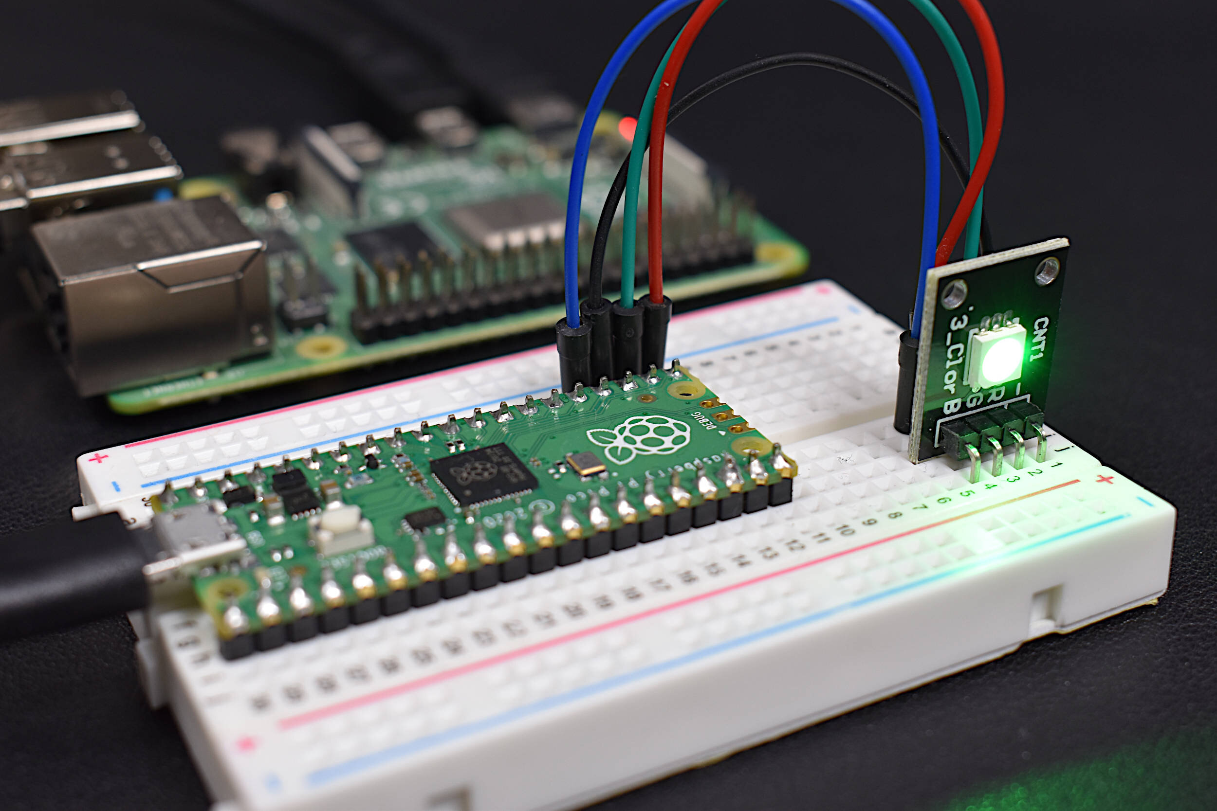
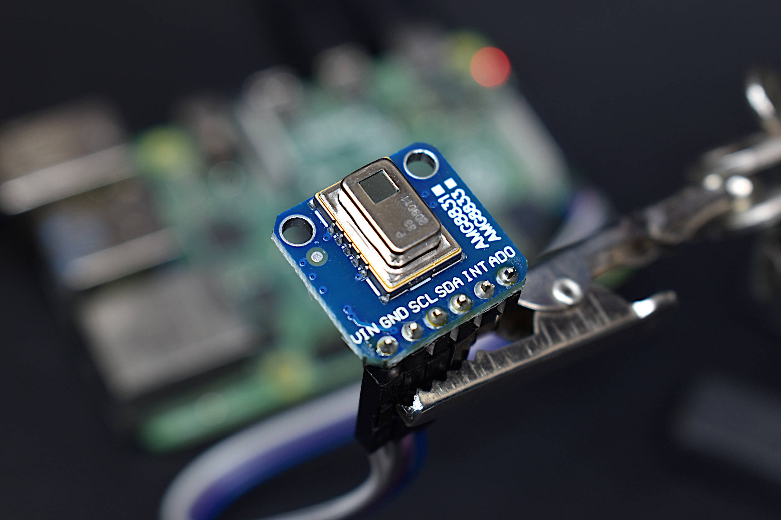
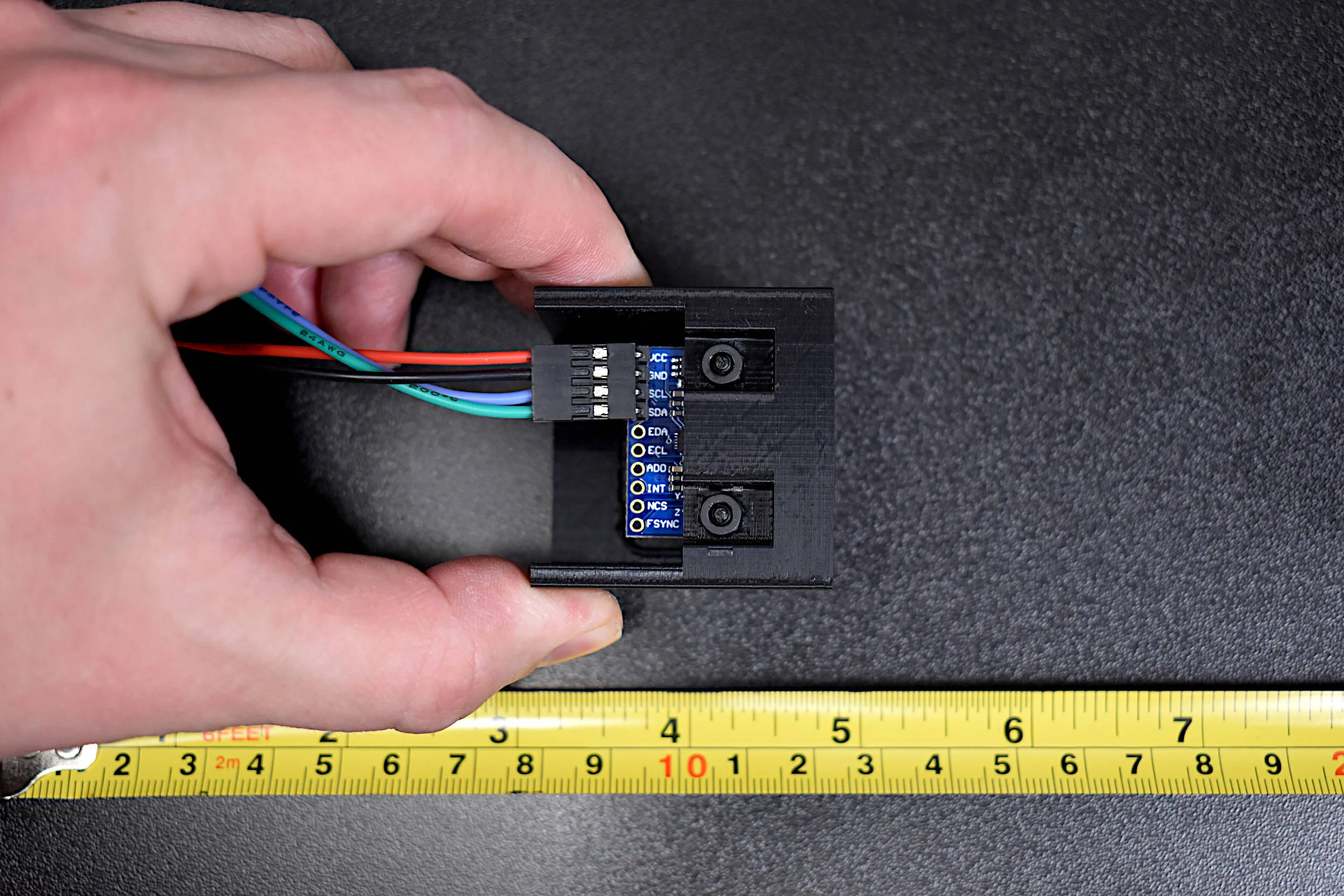
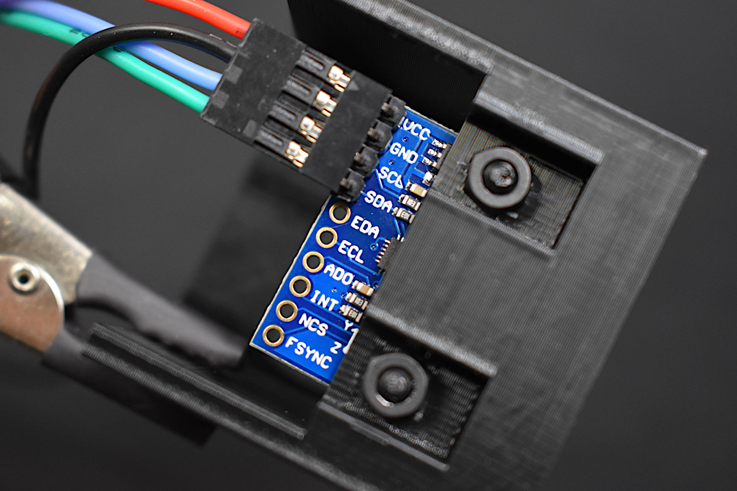
The wiring between the MPU9250 and the Raspberry Pi is given below:

The MPU9250 is powered via the 3.3V pin of the RPi, while the I2C pins on the IMU are wired to their corresponding SDA/SCL data pins on the RPi. In the next section, steps to prepare the Raspberry Pi for I2C communication will be introduced, which includes enabling the I2C bus and verifying the connection of the MPU9250 to the RPi using the i2c_detect command.
The following set of commands enables the I2C port on the RPi and ensures that the MPU9250 is properly wired to the RPi. The commands are also a near identical copy of our previous tutorial: https://makersportal.com/blog/2019/11/11/raspberry-pi-python-accelerometer-gyroscope-magnetometer#rpi-i2c
The MPU9250 will communicate with the Raspberry Pi using the I2C protocol. In order to read and write data via I2C, we must first enable the I2C ports on the RPi. The way we do this is either using the command line or by navigating to the Preferences → Raspberry Pi Configuration. Adafruit has a great tutorial outlining this process, but an abridged version will be given below using screenshots of the RPi configuration window.

1. Preferences → Raspberry Pi Configuration

2. Interfaces → Enable I2C
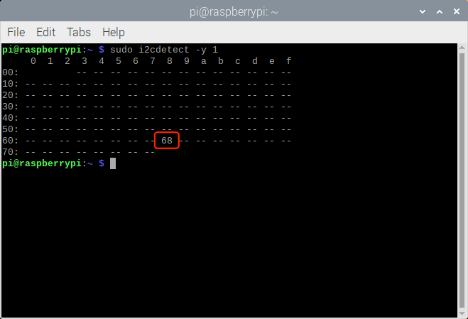
3. Open Command Window and type “sudo i2cdetect -y 1”
Verify 0x68 as the I2C available address
The 0x68 device is actually just the MPU6050 device, which houses only the accelerometer and gyroscope sensors. The magnetometer sensor, called AK8963 with device address: 0x0C, will be turned on once the RPi begins communicating with the MPU9250 (more on this later). In this tutorial, Python will be used to send and receive data from the MPU6050 and AK8963 sensors. We know at this point that the MPU6050 (accel/gyro) is functioning based on the listing of its I2C address (0x68), which we can verify from its datasheet. Similarly, we know we need to expect 0x0C from the AK8963 datasheet. More on the addresses and how the pass-through method of only requiring the 0x68 address works on the I2C bus can be found in the MPU9250 datasheet.
Going forward, it is assumed that the MPU9250 has been correctly wired to the RPi and that the MPU6050 device address (0x68) is showing up in the call to i2cdetect.
The last change to be made on the Raspberry Pi is the need to increase the speed of the I2C baud rate in order to get the fastest response from the MPU9250, which we can do by entering the following into the terminal’s command line:
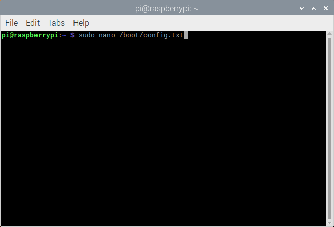
1. sudo nano /boot/config.txt

2. Add Configuration Next to I2C Setting
i2c_arm_baudrate=1000000
When finished changing the baud rate to 1Mbps, enter CTRL+X, Y, and then ENTER. This will save the new I2C baud rate. When finished, restart the RPi. All we are doing here is setting the baud rate to 1 Mbps - higher than the default of 100kbps. This should give us a sample rate of about 400Hz - 500Hz (after conversion to real-world units). We can achieve a much higher sample rate for the gyroscope and a slightly higher sample rate for the accelerometer, but that will not be explored in this series.
The GitHub page for this project contains all of the scripts and library codes used in this tutorial:
A few libraries need to be installed onto the Raspberry Pi before continuing with the calibration codes. The first is ‘scipy’ which we will use for fitting the calibration coefficients for each sensor. Assuming the user has Python 3.x installed with ‘pip’ - the following installs the scipy, matplotlib, and numpy packages, all of which are used in the calibration procedure:
pi@raspberrypi:~ $ sudo pip3 install scipy matplotlib numpy
The following may also be required for some Python 3.x versions and Raspberry Pi distributions:
pi@raspberrypi:~ $ sudo apt-get install libatlas-base-dev
Next, the I2C library and IMU test scripts (links below) need to be downloaded to the same local folder on the RPi, both of which can be found on the GitHub page for this project:
MPU9250 LIBRARY - https://raw.githubusercontent.com/makerportal/mpu92-calibration/main/mpu9250_i2c.py
TEST SCRIPT - https://raw.githubusercontent.com/makerportal/mpu92-calibration/main/imu_test.py
The ‘imu_test.py’ code is also listed below for reference:
######################################################
# Copyright (c) 2020 Maker Portal LLC
# Author: Joshua Hrisko
######################################################
#
# This code reads data from the MPU9250/MPU9265 board
# (MPU6050 - accel/gyro, AK8963 - mag) to verify its
# correct wiring to a Raspberry Pi and the functionality
# of the MPU9250_i2c.py library
#
#
######################################################
#
import time
t0 = time.time()
start_bool = False # boolean for connection
while (time.time()-t0)<5: # wait for 5-sec to connect to IMU
    try:
        from mpu9250_i2c import *
        start_bool = True # True for forthcoming loop
        break
    except:
        continue
#
#############################
# Strings for Units/Labs
#############################
#
imu_devs   = ["ACCELEROMETER","GYROSCOPE","MAGNETOMETER"]
imu_labels = ["x-dir","y-dir","z-dir"]
imu_units  = ["g","g","g","dps","dps","dps","uT","uT","uT"]
#
#############################
# Main Loop to Test IMU
#############################
#
while True:
    if start_bool==False: # make sure the IMU was started
        print("IMU not Started, Check Wiring") # check wiring if error
        break
    ##################################
    # Reading and Printing IMU values
    ##################################
    #
    try:
        ax,ay,az,wx,wy,wz = mpu6050_conv() # read and convert mpu6050 data
        mx,my,mz = AK8963_conv() # read and convert AK8963 magnetometer data
    except:
        continue
    #
    ##################################
    # Reading and Printing IMU values
    ##################################
    #
    print(50*"-")
    for imu_ii,imu_val in enumerate([ax,ay,az,wx,wy,wz,mx,my,mz]):
        if imu_ii%3==0:
            print(20*"_"+"\n"+imu_devs[int(imu_ii/3)]) # print sensor header
        #
        ###############
        # Print Data
        ###############
        #
        print("{0}: {1:3.2f} {2}".format(imu_labels[imu_ii%3],imu_val,imu_units[imu_ii]))

    time.sleep(1) # wait between prints
Upon successful run of the code above, the output should appear similar to the output shown in the screenshot below:

Example Printout from IMU Test Script
The above was printed out with the MPU9250 attached to the calibration block with the force due to gravity acting in the IMU’s z-direction. This is why we see a near 1g value in the z-dir, and almost 0g in the x- and y-directions. The accelerometer spans 0g-2g in its current configuration, but can be programmed to span up to 0g-16g.
For the gyroscope, we expect it to register near zero angular velocity, which we approximately see for all three directions. This, of course, is only true if the IMU is under stable conditions (not moving). The gyroscope spans 0-250 dps (degrees-per-second) in its current configuration, so we can make the assumption that the small values observed above are noise, small vibrations, or offsets to be calibrated out.
Lastly, the magnetometer shows the strength of Earth’s magnetic field to be approximately 17μT and 12μT. The magnetometer values are slightly more difficult to verify:
First, visiting the National Centers for Environmental Information’s (NCEI) magnetic field calculator: https://www.ngdc.noaa.gov/geomag/calculators/magcalc.shtml
Select the tab entitled: “Magnetic Field”
Next, input the IMU’s current geolocation coordinates (New York City, for our office: 40.7128° N, 74.0060° W)
Look for the component entitled: “Horizontal Intensity” - in our case it is 20,798 nT (20.8μT)

Next, square the x- and y-direction output values from the IMU:
For our case we get the following:
Thus, we can again verify that the IMU is behaving as expected in reference to the Earth’s magnetic field, since our measured horizontal declination is almost identical to the expected value according to the NCEI’s calculation. At this point, the user can verify that the IMU is functioning as expected for stationary conditions. This concludes the first portion of the calibration procedure for the MPU9250. In Part II of the tutorial, the actual calibration coefficients and methods for the accelerometer, gyroscope, and magnetometer will be explored in great depth.
In this first entry into the calibration of an inertial measurement unit (IMU), the MPU9250 was introduced along with the wiring of one specific IMU, the MPU9250, to a Raspberry Pi computer. The introductory testing of the MPU9250 was also introduced as a way of verifying both the communication between the Raspberry Pi and MPU9250 and the validity of each sensor aboard the MPU9250. Using the steady values recorded and printed out by Python, the IMU was verified as functioning properly and communicating appropriately with the RPi. The Earth’s gravitational field was registered as approximately 1g on each axis when perpendicular with gravity. Second, the gyroscope was confirmed as near zero when steady. Lastly, using the National Centers for Environmental Information’s magnetic field calculator for Earth, the horizontal components of the magnetometer were validated when compared with expected values for the IMU’s geographic coordinates.
In Part II of this series, the calibration coefficients for the gyroscope and accelerometer on the IMU will be explored, with specific calibrations for each sensor. The goal of this tutorial series is to improve the accuracy of the IMU for orientation mapping, heading navigation, dead reckoning, sports learning, vibration analyses, crash testing, among other application fields in inertial sensing. In Part II, there will be visualizations, animations, and examples of how proper calibration of the MPU9250 are useful for increasing the accuracy and implementation of the IMU. In Part III, the magnetometer calibration is introduced, along with the fusion of all three sensors and nine degrees-of-freedom.

See More in Raspberry Pi and Sensors: