Raspberry Pi Pico OLED Display (SSD1306)
“As an Amazon Associates Program member, clicking on links may result in Maker Portal receiving a small commission that helps support future projects.”
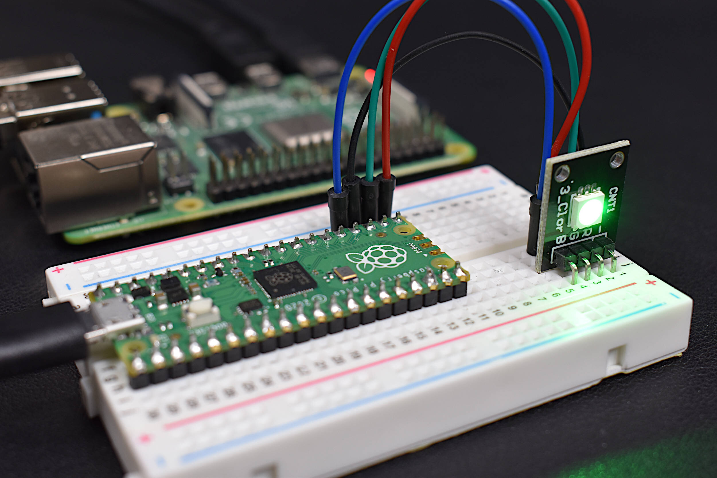
This is the third tutorial in a series dedicated to exploring the Raspberry Pi Foundation's groundbreaking new microcontroller: the Raspberry Pi Pico. The first entry centered on the basic principles of interfacing with the Pico and programming with Thonny and MicroPython, while the second entry focused on emulating the Google Home and Amazon Alexa LED animations with a WS2812 RGB LED array. In this tutorial, an SSD1306 organic light emitting diode (OLED) display will be controlled using the Pico microcontroller. A MicroPython library will be used as the base class for interfacing with the SSD1306, while custom algorithms are introduced to create data displays. Additionally, a custom Python3 algorithm will be given that allows users to show a custom image on the display. Lastly, a real-time plot will be created that shows an audio signal outputted by a MEMS microphone, emulating a real-time graph display. The SSD1306 is a useful tool for smaller scale projects that require real-time data displays, control feedback, and IoT testing. The power of the Pico microcontroller makes interfacing with the SSD1306 fast and easy, which will be evident when working with the Pico and SSD1306.
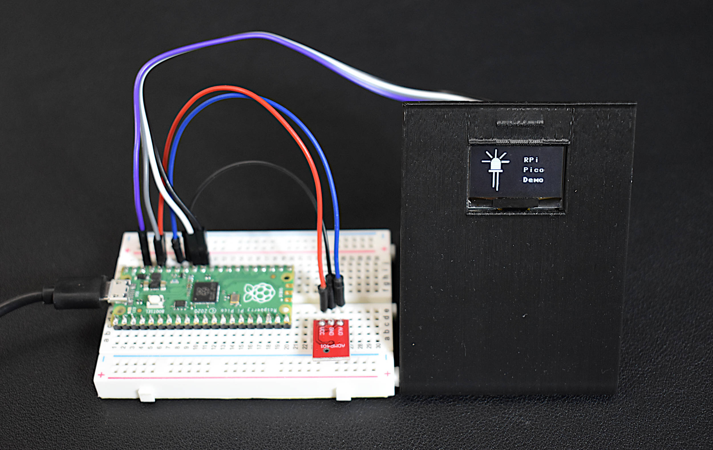
The Raspberry Pi Pico microcontroller and SSD1306 OLED display are the central components used in this tutorial, while a Raspberry Pi 4 computer is recommended for interfacing and programming on the Pico. A breadboard and some jumper wires will be helpful as well, and any sensor or motor that may be used in parallel with the SSD1306. The full parts list used to follow along with this tutorial is given below, with links:

The wiring diagram between the Pico (see the Pico pinout for reference) and SSD1306 display is given below:


The SSD1306 is wired to one of the Raspberry Pi Pico’s I2C port. On the Pico, there are two different I2C ports: I2C0, I2C1. We are wiring to the I2C1 port via GPIO pins 26/27 (physical pins 31/32). Any of the I2C-compatible pins can be used with the SSD1306. We are using GPIO26/27 due to their proximity to the power and ground pins being used. In the next section, the SSD1306 MicroPython library will be introduced and used to create a simple Raspberry Pi logo and text, based on the Pico’s MicroPython SDK document.
All of the codes used in this tutorial can be found at the project’s GitHub page:

Under the ‘micropython’ folder at the repository above there is a series of subfolders that contain examples that use the I2C MicroPython library that interfaces with the SSD1306. The file called sssd1306.py is the actual SSD1306 library, which must be uploaded to the Pico upon running each example file. The ssd1306.py library is given below for reference:
# MicroPython SSD1306 OLED driver using I2C interface
#
# library taken from repository at:
# https://github.com/micropython/micropython/blob/master/drivers/display/ssd1306.py
#
from micropython import const
import framebuf

# register definitions
SET_CONTRAST = const(0x81)
SET_ENTIRE_ON = const(0xA4)
SET_NORM_INV = const(0xA6)
SET_DISP = const(0xAE)
SET_MEM_ADDR = const(0x20)
SET_COL_ADDR = const(0x21)
SET_PAGE_ADDR = const(0x22)
SET_DISP_START_LINE = const(0x40)
SET_SEG_REMAP = const(0xA0)
SET_MUX_RATIO = const(0xA8)
SET_COM_OUT_DIR = const(0xC0)
SET_DISP_OFFSET = const(0xD3)
SET_COM_PIN_CFG = const(0xDA)
SET_DISP_CLK_DIV = const(0xD5)
SET_PRECHARGE = const(0xD9)
SET_VCOM_DESEL = const(0xDB)
SET_CHARGE_PUMP = const(0x8D)

# Subclassing FrameBuffer provides support for graphics primitives
# http://docs.micropython.org/en/latest/pyboard/library/framebuf.html
class SSD1306(framebuf.FrameBuffer):
    def __init__(self, width, height, external_vcc):
        self.width = width
        self.height = height
        self.external_vcc = external_vcc
        self.pages = self.height // 8
        self.buffer = bytearray(self.pages * self.width)
        super().__init__(self.buffer, self.width, self.height, framebuf.MONO_VLSB)
        self.init_display()

    def init_display(self):
        for cmd in (
            SET_DISP | 0x00,  # off
            # address setting
            SET_MEM_ADDR,
            0x00,  # horizontal
            # resolution and layout
            SET_DISP_START_LINE | 0x00,
            SET_SEG_REMAP | 0x01,  # column addr 127 mapped to SEG0
            SET_MUX_RATIO,
            self.height - 1,
            SET_COM_OUT_DIR | 0x08,  # scan from COM[N] to COM0
            SET_DISP_OFFSET,
            0x00,
            SET_COM_PIN_CFG,
            0x02 if self.width > 2 * self.height else 0x12,
            # timing and driving scheme
            SET_DISP_CLK_DIV,
            0x80,
            SET_PRECHARGE,
            0x22 if self.external_vcc else 0xF1,
            SET_VCOM_DESEL,
            0x30,  # 0.83*Vcc
            # display
            SET_CONTRAST,
            0xFF,  # maximum
            SET_ENTIRE_ON,  # output follows RAM contents
            SET_NORM_INV,  # not inverted
            # charge pump
            SET_CHARGE_PUMP,
            0x10 if self.external_vcc else 0x14,
            SET_DISP | 0x01,
        ):  # on
            self.write_cmd(cmd)
        self.fill(0)
        self.show()

    def poweroff(self):
        self.write_cmd(SET_DISP | 0x00)

    def poweron(self):
        self.write_cmd(SET_DISP | 0x01)

    def contrast(self, contrast):
        self.write_cmd(SET_CONTRAST)
        self.write_cmd(contrast)

    def invert(self, invert):
        self.write_cmd(SET_NORM_INV | (invert & 1))

    def show(self):
        x0 = 0
        x1 = self.width - 1
        if self.width == 64:
            # displays with width of 64 pixels are shifted by 32
            x0 += 32
            x1 += 32
        self.write_cmd(SET_COL_ADDR)
        self.write_cmd(x0)
        self.write_cmd(x1)
        self.write_cmd(SET_PAGE_ADDR)
        self.write_cmd(0)
        self.write_cmd(self.pages - 1)
        self.write_data(self.buffer)


class SSD1306_I2C(SSD1306):
    def __init__(self, width, height, i2c, addr=0x3C, external_vcc=False):
        self.i2c = i2c
        self.addr = addr
        self.temp = bytearray(2)
        self.write_list = [b"\x40", None]  # Co=0, D/C#=1
        super().__init__(width, height, external_vcc)

    def write_cmd(self, cmd):
        self.temp[0] = 0x80  # Co=1, D/C#=0
        self.temp[1] = cmd
        self.i2c.writeto(self.addr, self.temp)

    def write_data(self, buf):
        self.write_list[1] = buf
        self.i2c.writevto(self.addr, self.write_list)
The library above is taken directly from the MicroPython GitHub page. The set of registers given at the top of the code above outline many of the commands used to control and interact with the SSD1306. The I2C port on the Pico carries out the commands that set the parameters relevant to the SSD1306, for example, the width, height, frequency, color mapping, etc. Going forward, the library will be used for each example but will not be referenced further. Instead, the examples will focus on applications of the library, such as displaying images, writing and coordinating text, inverting the display, among others.
NOTE: The ssd1306.py and main.py are both required when controlling the SSD1306 OLED Display with the RPi Pico

Minimum Requirements When Interfacing with the SSD1306 Display
This section focuses on displaying an image and writing text next to the image at the same time. Two examples are given on the GitHub page, as follows:
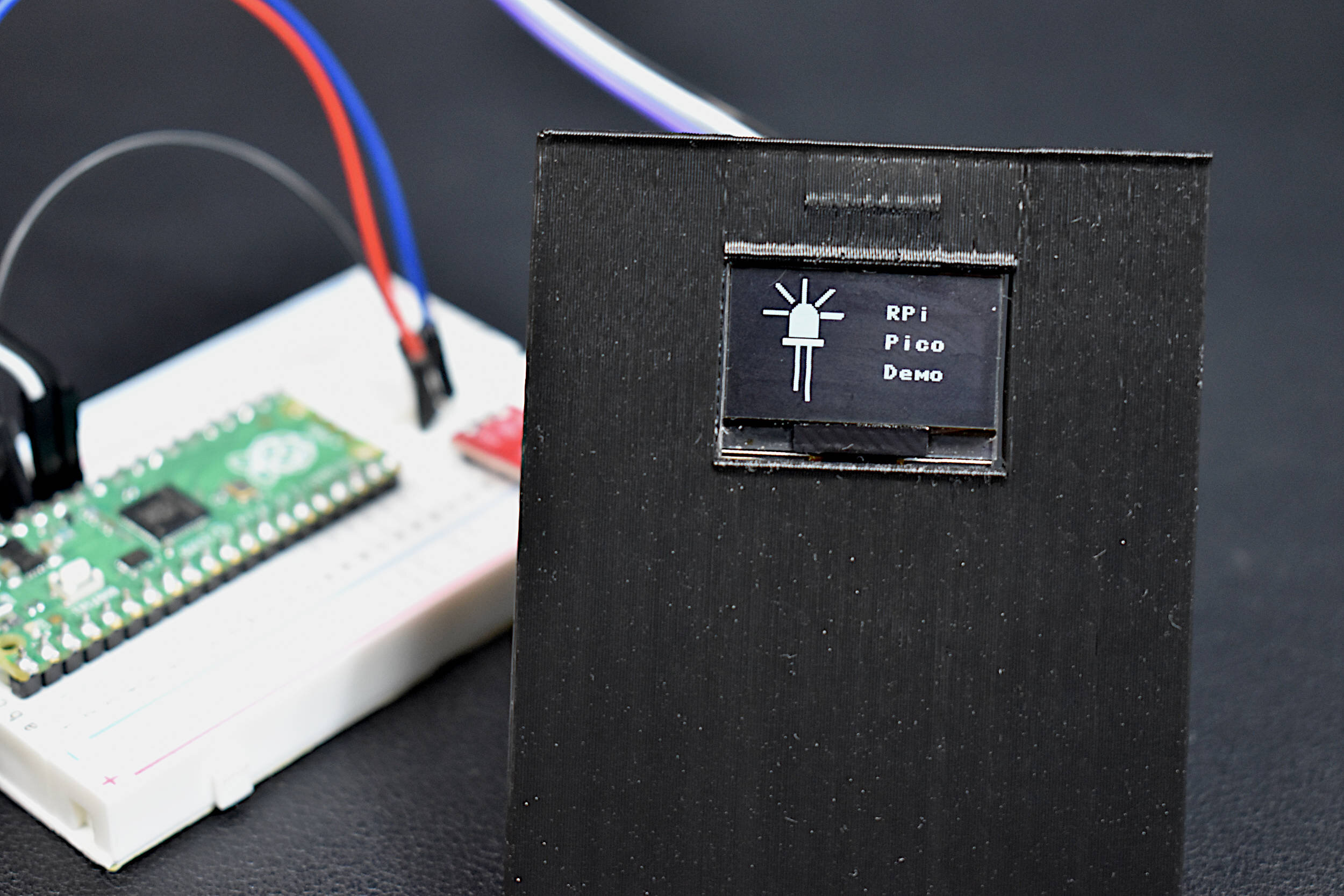
Raspberry Pi Logo Display - This is the Raspberry Pi Pico demonstration for the SSD1306. It displays the Raspberry Pi logo with the text ‘Raspberry Pi Pico’ displayed next to it
Custom Logo Display - This code displays a custom logo uploaded to ‘imgfile.py’ created by the custom Python3 script. Using an image, a Python3 script converts an image to a byte array. This byte array needs to be uploaded to the imgfile.py in bytearray() form. Then, the main script displays this image on the SSD1306.
In this section, we focus on the custom logo display. Users can easily copy and paste and try the Raspberry Pi logo display. It is similar to the custom logo display, but uses the RPi logo.
Preparing the Custom Logo for Display
A custom .png image file should be placed in the ‘python3’ folder. Then, on a Raspberry Pi or other computer, the ‘png_to_bytearray.py’ script should be run. It will print out a custom bytearray():

This is the image format that needs to be copied and pasted into the /micropython/logo_display/imgfile.py file:

Insert the bytearray() printed above into the imgfile.py on the Pico
The script also prints out the image resolution, which in our case is 64x64 pixels, which should also be updated into the main.py file. After copying the byte array above into the imgfile.py, run the main.py file and observe the newly printed logo on the SSD1306 display!
The text display has also been built out from the original Pico demonstration on the MicroPython SDK. The text display snippet is given below as an example (code can be found at the GitHub Page):
start_x = 75 # start point for text in x-dir
start_y = 12 # start point for text in y-dir
lineskip = 15 # space between text in y-dir
txt_array = ['RPi','Pico','Demo']
for iter_ii,txt in enumerate(txt_array):
    oled.text(txt,start_x,start_y+(iter_ii*lineskip)) # add text at (start_x,start_y)

oled.show() # show the new text and image
The snippet above takes a text array and places the text vertically in the display window. Depending on the starting x,y values and the skip between lines, the text will appear a certain way within the window. It’s a very simple placement of text, without any control over overflow (text past the window extents), text size, or vertical or horizontal centering.
An example output displaying one of our logos on the SSD1306 is given below:
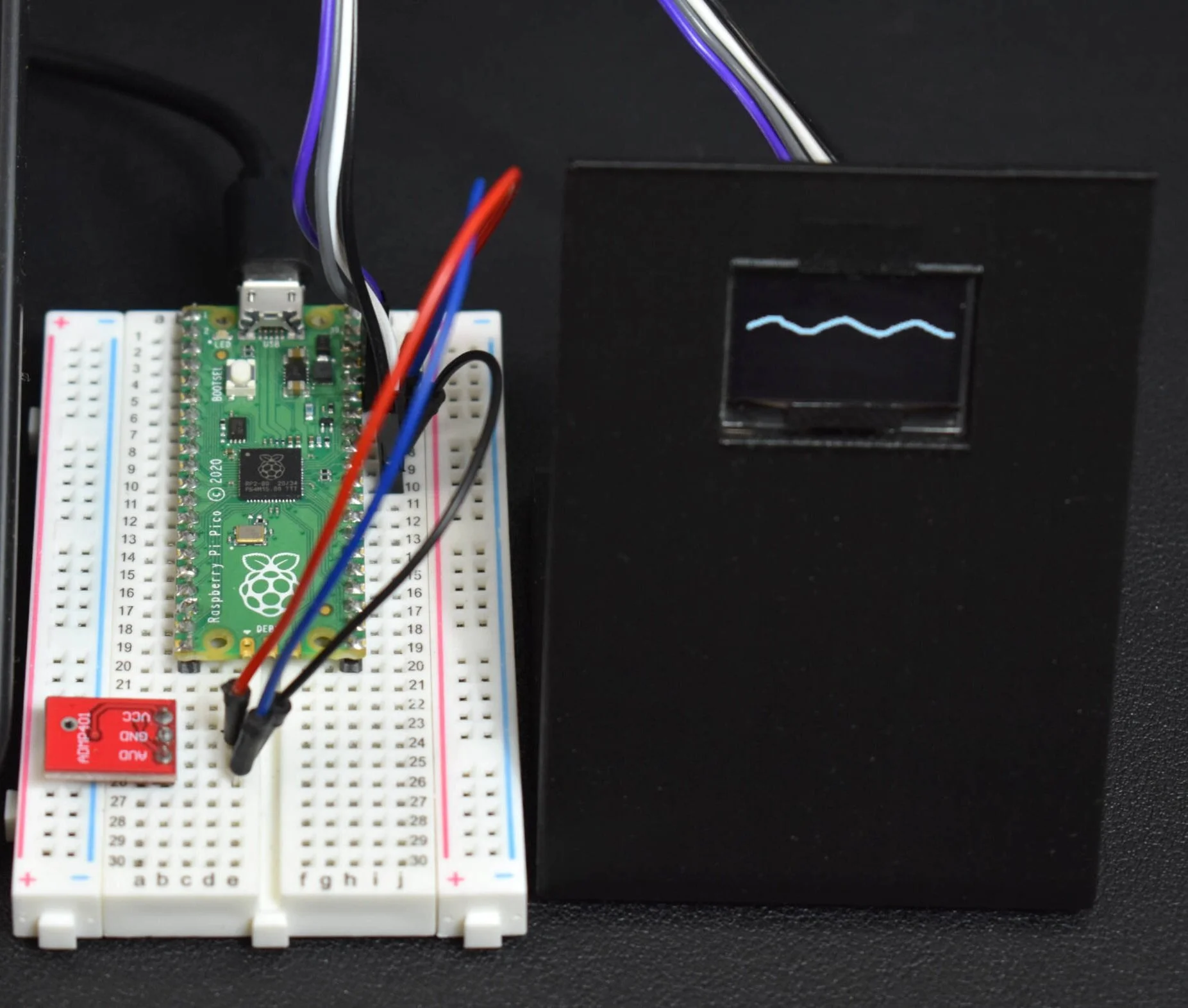
In this section, the limits of the SSD1306 were pushed by testing the display with a real-time signal. A MEMS microphone with analog output was selected as the time-varying signal to be read by the Pico microcontroller. Then, the signal will be plotted on the OLED display in dot format. This emulates an audio signal and is capable of replicating the wave form of a signal in pseudo real-time. The speed of the ADC is fast enough for audio, which is read at high speed, then plotted when the OLED becomes available for refresh again. We were able to get update rates of roughly 15 Hz, or 15 refreshes per second.
For the data display in real time, we must first use the analog-to-digital converter to read a sensor. As stated above, a MEMS microphone was being used, however, any sensor that produces data in real time can be used. The data will be read using the follow snippet of code (full code here):
adc_2 = machine.ADC(2) # ADC channel 2 for input
while True:
    oled.fill(0) # clear the display
    for jj in range(pix_res_x): # loop through horizontal display resolution
        adc_pt = adc_2.read_u16() # read adc and get 16-bit data point
        plot_pt = (adc_pt/((2**16)-1))*(pix_res_y-1) # convert to OLED pixels
        oled.text('.',jj,int(plot_pt)) # update x=jj with data point
    oled.show() # show the new text and image
We are using the analog input pin #2, which correlates to physical pin #34 and GPIO28. Also, the snippet above loops through all 128 pixels on the horizontal display dimension and places a new data point from the ADC onto that point, thus, giving a real-time plot emulator. Of course, there will be a significant delay between each plot update, which is noticeable when using a high-speed input such as a microphone.
Below is a clip of the SSD1306 displaying a real-time wave of 250Hz outputted by a smartphone and being read by a MEMS microphone:
The demonstration above really shows the capabilities of the Raspberry Pi Pico and its ability to capture waveforms of a specific audio signal. Of course, users may want to add axes and labels to the plot for real-time analysis, however, the demonstration proves that the SSD1306 is a highly capable device and able to be integrated with the Pico microcontroller via MicroPython.
In this third entry to the the Raspberry Pi Pico microcontroller tutorial series, an SSD1306 OLED display was interfaced via the I2C port of the Pico. A MicroPython library was introduced to control the SSD1306 display, along with a few scripts that display custom logos and real-time data plots. A separate Python3 program is given that allows users to create their own custom image to be displayed on the OLED. The real-time data display was able to refresh 128 data points at a rate of 15Hz (15 refreshes per second), which was capable of showing waveforms produced by an analog MEMS microphone. The SSD1306 is a useful tool for visualizations and printing out information related to sensors and modules — specifically when developing internet of things (IoT) nodes that wirelessly send and receive data or control motors and actuators. This tutorial was meant as a further exploration into the Raspberry Pi Pico microcontroller, with a focus on I2C communication. In the future of this series, more peripherals will be tested, such as SPI, UART, analog-to-digital conversion specifics, and even the capabilities of the dual-processor!
See More in Raspberry Pi and Pico:


