Arduino Internet of Things Part 4: Connecting Bluetooth Nodes to the Raspberry Pi Using Python's Bluepy Library
In the previous three installments of the Arduino Internet of Things series, I walked through building an inexpensive, $3, breadboard Arduino (Part 1); I demonstrated how to record temperature and send the data via Bluetooth using the Arduino (Part 2); and I instructed how to use interrupt techniques with a motion sensor to create a Bluetooth node that will last for months on a single LiPo battery charge (Part 3). In this tutorial I explain how to connect all of these devices via Bluetooth Low Energy (BLE) and communicate with a Raspberry Pi to prepare the system for integration into the Internet of Things (IoT). At the end of this tutorial, the user's Raspberry Pi will be able to listen for multiple Bluetooth devices and record the data transmitted by each node. I will start by implementing the Python-enabled Bluetooth library, Bluepy, and showing the user how to scan for BLE devices.
Downloading and Testing Bluepy for Python on Raspberry Pi
Bluepy is a Bluetooth Low Energy interface built on Raspberry Pi for Python. The GitHub page can be found here. I have used Bluepy for many different Bluetooth LE projects ranging from iBeacons to multi-node IoT frameworks. It's great for IoT applications because of its integration with Raspberry Pi and Python. Below is the outline of the install process for Python 3.xx via the command window. As of writing, this method worked for the Raspberry Pi 3 Model B+.
sudo apt-get install python3-pip libglib2.0-dev
sudo pip3 install bluepy
Once the Pi is restarted and a text editor is opened, copy the following code from the Bluepy documentation (docs here) into the file and save it as 'ble_scanner.py'
from bluepy.btle import Scanner, DefaultDelegate

class ScanDelegate(DefaultDelegate):
    def __init__(self):
        DefaultDelegate.__init__(self)

    def handleDiscovery(self, dev, isNewDev, isNewData):
        if isNewDev:
            print "Discovered device", dev.addr
        elif isNewData:
            print "Received new data from", dev.addr

scanner = Scanner().withDelegate(ScanDelegate())
devices = scanner.scan(10.0)

for dev in devices:
    print "Device %s (%s), RSSI=%d dB" % (dev.addr, dev.addrType, dev.rssi)
    for (adtype, desc, value) in dev.getScanData():
        print "  %s = %s" % (desc, value)
After saving the code above, open the command window and navigate to the file's directory. Then, start the file in the command window. The command window needs to be user for permissions reasons.
sudo python3 ble_scanner.py
You should be seeing results that look something like this:

The printout above shows the Each Bluetooth Low Energy device address that the Raspberry Pi was able to read during its scan. The six hex values in 'Device xx:xx:xx:xx:xx:xx' is the unique address for each BLE device. You can also see information about received signal strength (RSSI) and other BLE information. This step is only to test that Bluepy is working correctly on your RPi. In the next step, we will investigate how to read data from specific devices.
Finding BLE Addresses with Arduino Uno
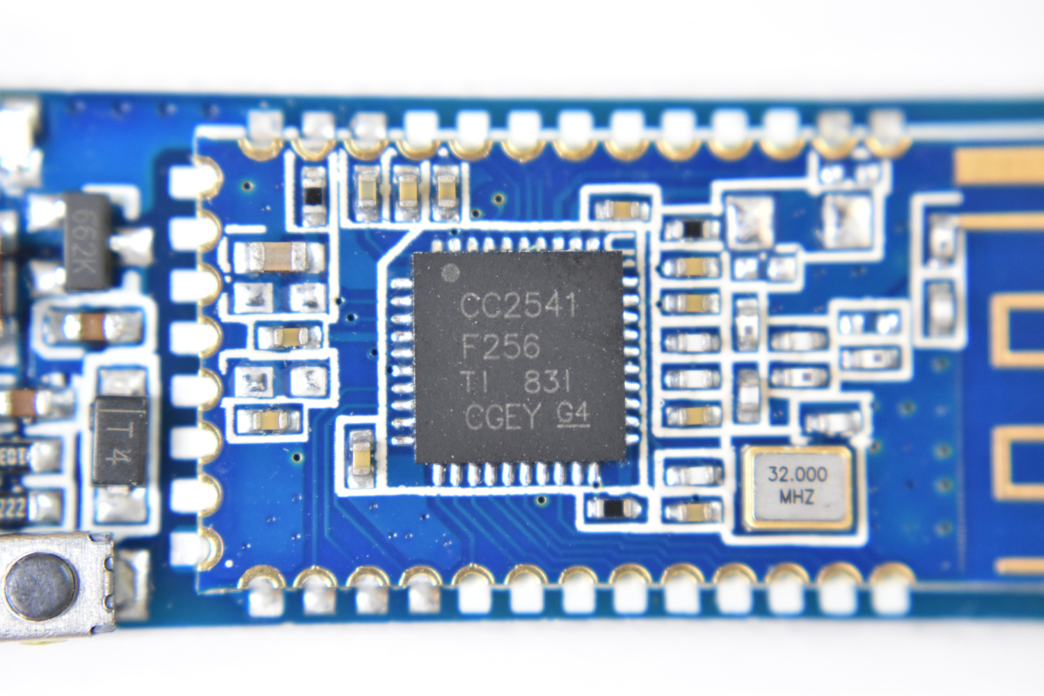
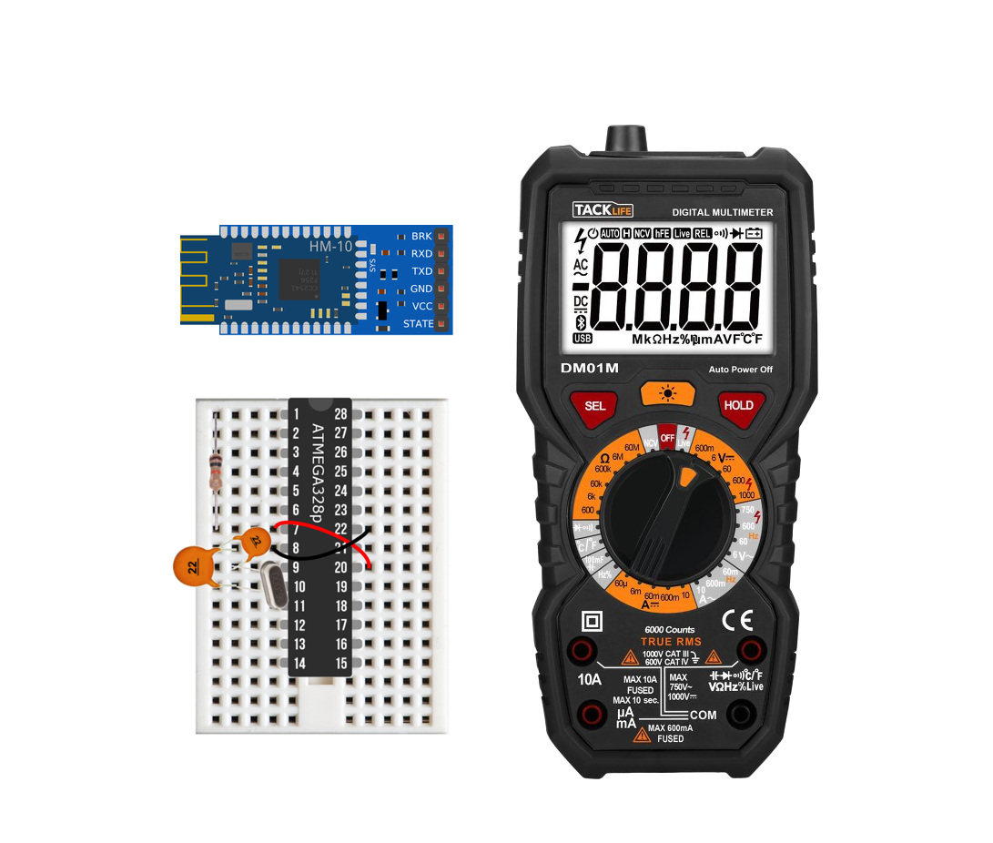
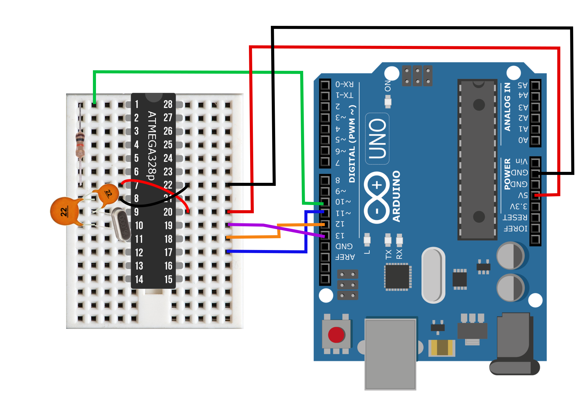
In order to connect the BLE nodes to the Raspberry Pi, we need to ensure that we have the BLE addresses for each node. Another alternative would be to name each device and then conduct a scan for specific keywords, but that is a much more complicated problem that can be explored once the user has a basic understanding of the Bluepy protocol and BLE behavior. To acquire the Bluetooth address of each BLE device, you will need to connect the TX/RX pins of the HM-10 to the TX/RX of the Arduino Uno board (as shown in Figure 1 below, taken from my HM-10 iBeacon tutorial).
Figure 1: Wiring for obtaining Bluetooth address from CC25xx/HM-10 modules.
In order to communicate with the HM-10 the user will need to utilize the AT command set. AT commands are a specific protocol for instructing the BLE module. First, the letters AT are used, then a + sign, then the specific command. For example, to instruct the module to print its Bluetooth address, you would type into the Arduino Serial window: 'AT+ADDR?' and the response should be 'AT+ADDR:XXXXXXXXXXXX' where the Xs are 12 unique numbers and letters that designate the Bluetooth address of the HM-10 (six hex values).
To start, it's always a good idea to type in 'AT' to which you should receive 'OK' as a response. This tells you that the communication line is established between the Arduino and the HM-10. If you receive nothing, try switching the TX/RX wires. If there's still nothing, then try going to the bottom of the window and clicking where it says 'No line ending' and select 'Both NL & CR' - this will put a newline and carriage return at the end of each command. This function works for some CC254x modules that do not have the full HM-10 firmware installed (with the crystal). The 'Both NL & CR' is selected in my example in Figure 2.

Figure 2: Screenshot showing the result of 'AT+ADDR?' in the Arduino serial monitor. You should do this for each Bluetooth module and store the values in a list either in a Python code or elsewhere.
Listening for and Reading from A Specific BLE Module
Now that we have installed Bluepy and acquired the address of each BLE module, we can create a script in Python to read data from any node. Bluepy's official documentation is great for getting started (find it here). Essentially, Bluepy handles a lot of the Bluetooth protocols, but we still need to tell it what to listen for and how to handle the data. Below is a (slightly) modified version from Bluepy's documentation:
from bluepy import btle
import struct

class MyDelegate(btle.DefaultDelegate):
    def __init__(self,params):
        btle.DefaultDelegate.__init__(self)

    def handleNotification(self,cHandle,data):
        print("handling notification...")
##        print(self)
##        print(cHandle)
        print(struct.unpack("b",data))

p = btle.Peripheral('00:15:87:00:4e:d4')
p.setDelegate(MyDelegate(0))

while True:
    if p.waitForNotifications(1.0):
        continue
    print("waiting...")
The code above tells Python to look for the device at address '00:15:87:00:4E:D4' and wait for intervals of 1 second for data to be received. When the BLE device wakes, the Python program should print 'waiting...' until data is received. The program will also exit with an error stating that the 'Device disconnected.' This is okay in our case because we actually ARE disconnecting the device on the Arduino end. But for testing purposes, this code functions just fine. You should receive data (assuming you're using temperature data from the Arduino IoT node) that looks like the following:
waiting...
waiting...
waiting...
waiting...
waiting...
handling notification...
(23,)
handling notification...
(50,)
waiting...
waiting...
waiting...
In the results above, the temperature data can be read as '23.50 degrees Celsius.' If you decide to program the data in a different way (on the Arduino side), your 'struct.unpack("b",data) will look a bit different. More on the 'struct' class in Python can be found here.
Looping and Listening for Multiple Devices
The full coop code can be found here. In short, it uses the 'concurrent futures' Python library (see here) to parallel-ize listening and reading for multiple Bluetooth Low Energy devices that are transmitting data. The loop also sends a byte of data back to the BLE module to be read on the device's end. The BLE devices can be programmed to read on the Arduino end and react accordingly. If you're using the Arduino IDE serial port, you can also listen for the transmitted data and verify the two-way communication using only an HM-10/CC2541 module (this is the only one I tested).

Conclusion
At this point, the Raspberry Pi can read multiple BLE nodes and record data. This means that within the loop, the data can be stored or uploaded to the internet to complete the integration into the Internet of Things. In the final installation of this tutorial series, I will cover one method of connecting to the internet using Python and Google Drive. This will allow the user to send data to the Raspberry Pi via several IoT nodes and then upload the data to the internet.
Products from our Shop relevant to this tutorial:

The Raspberry Pi 4 Computer, Model B is the latest in the series of single-board computers (SBC) produced by the Raspberry Pi Foundation. The RPi 4 increased its processor speed, its GPU performance, memory (1GB, 2GB, 4B, 8GB options), and connectivity. The Raspberry Pi 4 computer continues to be an essential tool in the maker, programmer, and engineer communities. The Raspberry Pi 4 is capable of interfacing with a wide range of sensors, motors, actuators, and devices. The RPi 4 has the standard 40-pin header with general purpose input/outputs (GPIOs), Bluetooth and WiFi capabilities, HDMI output display abilities, and much more! Our site contains a variety of different tutorials in the categories of Python programming, data acquisition and analysis, motor control, internet of things (IoT), engineering, among others.
Included with the Raspberry Pi 4 Model B Computer:
1x Raspberry Pi 4 Model B Computer
Features of the Raspberry Pi 4 Model B Computer:
Broadcom BCM2711, Quad core Cortex-A72 (ARM v8) 64-bit SoC @ 1.5GHz
LPDDR4-3200 SDRAM (2GB, 4GB, 8GB depending on the model)
2.4 GHz and 5.0 GHz WiFi, Bluetooth 5.0, Bluetooth Low Energy (BLE)
Gigabit Ethernet
2x USB 3.0 ports; 2x USB 2.0 ports
Raspberry Pi standard 40-pin GPIO header (fully backwards compatible with previous boards)
2x micro-HDMI ports (up to 4K @60fps supported)
2-lane MIPI DSI display port, 2-lane MIPI CSI camera port
4-pole stereo audio and composite video port
H.265 (4kp60 decode), H264 (1080p60 decode, 1080p30 encode)
Micro-SD card slot for loading operating system and data storage
5V DC via USB-C connector, 5V DC via GPIO header (3A Recommended Supply)
Operating Temperature (Ambient): 0°C – 50°C
Raspberry Pi Peripherals:
6x UART, 6x I2C, 5x SPI, 1x SDIO, 1x DPI, 1x PCM, 2x PWM Channels, 3x GPCLK
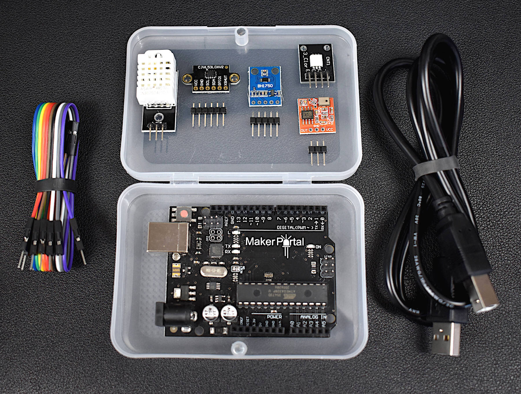
This Arduino starter kit has been tailored directly to engineers interested in real-world applications involving sensors. We avoided many of the out-of-date sensors that often accompany Arduino kits and targeted several relevant and interesting areas of engineering: temperature and humidity sensing, infrared time-of-flight distance sensing, and visible spectrum light intensity detection, and MEMS microphone audio sensing. In conjunction with these sensors, the kit also comes with an Arduino Uno microcontroller, jumper wires for connecting the sensors, an RGB LED indicator, and plastic component enclosure.
Included in the Arduino Starter Kit for Engineers (Sensor Suite):
1x Maker Portal Arduino Uno Board
1x BH1750 Light Sensor
1x DHT22 Temperature and Humidity Sensor
1x VL53L0X Time-of-Flight Distance Sensor
1x MEMS Microphone
1x RGB LED
10x Male-to-Female Jumper Wires
1x Plastic Component Box
1x USB 2.0 Cable for Arduino
Features of the Arduino Starter Kit for Engineers (Sensor Suite):
Detect light, temperature, humidity, distance, and sound
All sensors have easy-to-use Arduino-compatible libraries
The kit fits snugly into the component box, excluding the USB cable
Each sensor has a real-world application for prototyping in topics ranging from: environmental monitoring, industrial engineering, obstacle avoidance in robotics, home automation, and more!
Component Specifications:
-Specifications for the Arduino Uno Board:
ATmega328P chip with Arduino Bootloader
14 digital pins, 6 analog pins
10-bit analog-to-digital converter (ADC)
5V-12V Supply Tolerance
3.3V and 5.0V output pins
16 MHz clock
5 PWM pins, I2C support, SPI support , UART support
ATmega16U2 USB TTL, compatible with Linux, Windows, and Mac
Black Stylish Finish
Fully Integrated with Arduino IDE software
-Features of the BH1750 Light Sensor:
3.3V - 5.0V Input Voltage
16-bit ADC: 1 - 65535 lx Range
8-60Hz Sample Rate
I2C 2-Wire Communication Protocol
Supply Current - 120 µA, Power-down Current 0.01 µA
Peak Current - 7mA
400nm - 700nm Wavelength Response
-Features of the DHT22 Temperature Sensor:
3.3-6V Supply Voltage
Operating ranges:
Relative Humidity: 0-100 %
Temperature -40 °C to 80 °C
Sample Rate ~ 2 seconds
Sensitivity:
Relative Humidity: ± 0.1 %
Temperature: ± 0.1 °C
Accuracy (Drift and calibration errors):
Relative Humidity: ± 2-5 %
Temperature: ±0.5 °C
-Features of the VL53L0X ToF Sensor:
3.3V Supply Voltage
<20 mA consumption
50mm - 1.2m range (default mode), 50mm - 2.2m range (long range mode)
5 Hz - 33 Hz Sample Rate
I2C Compatible with Arduino, Raspberry Pi
Class I Infrared Laser (safe under all conditions)
-Features of the Analog MEMS Microphone:
3.0V-7.0V Supply Range
-42dBV/Pa Sensitivity
59dBA Signal-to-Noise Ratio (SNR) @ 1kHz
16mm x 15mm x 3.1mm Module Dimensions
4.72mm x 3.76mm MEMS Microphone Dimensions
100Hz - 10kHz Frequency Range (within 4dB)
3mA - 10mA Average Consumption
SPM0404HD5-PB MEMS Microphone Datasheet

The DHT22 temperature and humidity sensor is used in many projects involving smart home automation, weather monitoring, and horticulture management. It is a great sensor for getting started with Arduino and Raspberry Pi datalogging and data analysis using real-world data, i.e. temperature and humidity.
Included in the DHT22 Temperature Sensor Breakout Package:
DHT22 temperature and humidity sensor
Jumper wires
Features of the DHT22 Temperature Sensor:
3.3-6V Supply Voltage
Operating ranges:
Relative Humidity: 0-100 %
Temperature -40 °C to 80 °C
Sample Rate ~ 2 seconds
Sensitivity:
Relative Humidity: ± 0.1 %
Temperature: ± 0.1 °C
Accuracy (Drift and calibration errors):
Relative Humidity: ± 2-5 %
Temperature: ±0.5 °C
Compatible with both Raspberry Pi and Arduino!
Read the datasheet here
See our Tutorials using the DHT22:

The NEMA 17 stepper motor (Model: 17HS4023) is a powerful motor capable of microstepping, high-speed rotation, and high-torque holding. The stepper motor kit also includes a DRV8825 stepper driver and motor bridge, which makes getting started with motor driving easy. With the stepper bridge, only a Raspberry Pi or Arduino, 12V supply, and five jumper wires are needed to control the NEMA 17 stepper motor. This stepper kit can be used in applications involving 3D printers, DIY CNC machines, precise camera movement, LiDAR rotation, among others!
Included in the NEMA 17 Stepper Motor Kit:
1x NEMA-17HS4023 Stepper Motor
1x DRV8825 Stepper Driver with Heat Sink
1x DRV8825 Driver Bridge
5x Female-to-Female Jumper Wires
1x Stepper-to-Bridge Connector Wire
Features of the NEMA-17HS4023 Motor:
42mm x 42mm x 23mm (LxWxH - Approximate Dimensions)
Micro-stepping down from 1.8° down to 0.05625°
Wide Voltage Supply Range: 5V - 24V
0.7A - 1.0A per phase (2-phases total)
130g Weight
13 N·cm Holding Torque
Clockwise and Counterclockwise Rotation
Rotation speeds at 1.8° Increments up to ~500RPM (12V, no load), ~1800RPM (24V, no load)
Controllable via Arduino or Raspberry Pi
Tutorial on the NEMA 17 Kit here