Arduino Internet of Things Part 2: Lowering The Power Consumption Of The ATmega328P Breadboard Arduino And The HM-10 Bluetooth Module

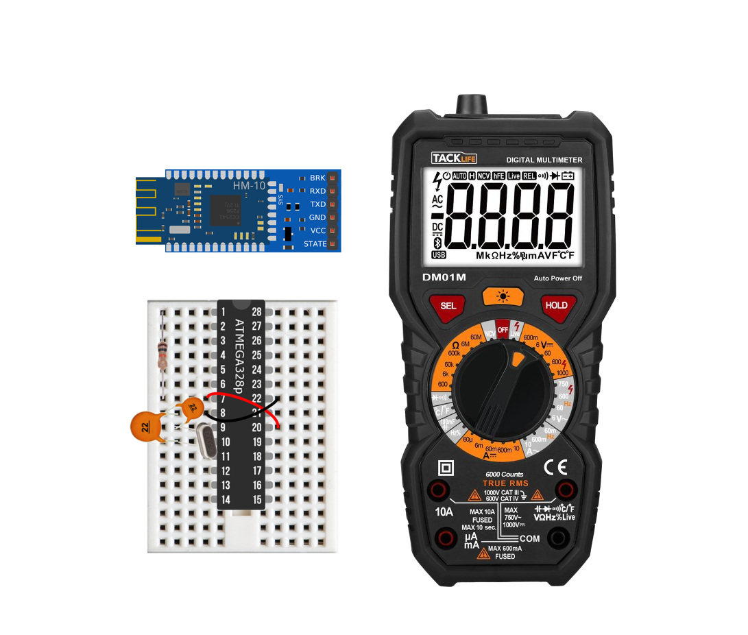
Tacklife DM01M Digital Multimeter For Measuring Low Currents
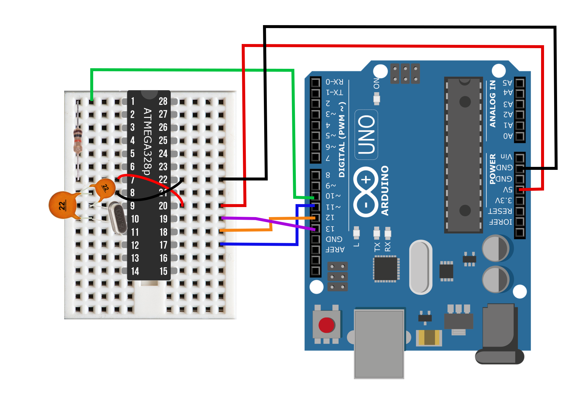
This is the second entry into the Arduino Internet of Things Series that explores the power consumption of the breadboard Arduino paired with the HM-10 Bluetooth module. Part 1 of this series covered wiring the Uno board for in-circuit serial programming, burning the Arduino bootloader onto a blank ATmega328P chip, and uploading sketches to the breadboard Arduino. If you missed the first entry, click here. If you're up to speed, continue reading for elucidation on: lowering power consumption via the frequency of the quartz crystal, the low-power library for Arduino, and the trade-off between low-power sleep modes and communication delays. The primary goal here is to extend the battery life of the Bluetooth-enabled breadboard Arduino for long-term integration into the Internet of Things (IoT).
A high-resolution multimeter will be necessary for this tutorial because we will be investigating currents in the µA range. I bought the Tacklife DM01M digital multimeter from Amazon ($14.19 at the time of writing). The DM01M is great because it has a resolution of 0.01 µA at its finest resolution and is capable of reading out the sleep currents - something that will be essential to our experiments here that will determine the best cycles for our IoT applications.
Quartz Crystal Influence on Power Consumption
Perhaps the most important and critical component in the breadboard Arduino is the quartz crystal oscillator. The oscillator's job is to keep accurate timing between the microcontroller (ATmega328P) and Bluetooth module to ensure that serial protocol is synchronized and information is not lost or mismatched. The oscillator is of utmost important to our case because it also draws a significant amount of power during operation. Therefore, the crystal oscillator is not only essential, but also a hindrance if poorly prescribed. For our breadboard Arduino, it is necessary to not only pick the most efficient crystal, but also to ensure that it functions with the HM-10 Bluetooth module.
I decreased the oscillator frequency until just before the critical point where the ATmega328P requires fuse switching - something I wanted to avoid for simplicity's sake. This minimal frequency was 3 MHz, but I chose 4 MHz, because it was the oscillator available to me at the time. Then I chose an 8 MHz oscillator for in-between the 16 MHz (traditional Arduino Uno crystal) and 4 MHz components. The table below outlines the consumption due to the three crystal oscillators at two different operating voltages.
| Crystal Frequency [MHz] | Active Current [mA] @ 3.3V |
Sleep Current [µA] @ 3.3V |
Active Current [mA] @ 3.7V | Sleep Current [µA] @ 3.7V |
|---|---|---|---|---|
| 16 | 6.5 | 4.41 | 9.3 | 5.1 |
| 8 | 3.8 | 4.41 | 5.5 | 5.1 |
| 4 | 2.3 | 4.41 | 3.7 | 5.1 |
The table above reveals several conditions of the component alterations:
Lowering the crystal frequency lowers the power consumption during normal operation.
The sleep current is unaffected by the crystal oscillator
Lowering the supply current lowers the power consumption
I also want to note that the low-power current results above are similar to others' findings on Arduino power consumption [Arduino Low Power - How To Run ATmega328P for a Year on Coin Cell Battery, Reducing Arduino Power Consumption].
NOTE: The reason why I compare 3.3V and 3.7V here is because the Arduino Uno is traditionally 3.3V and low voltage LiPo batteries are typically 3.7V and are quite cheap because of their ubiquity in drones. Unfortunately, we cannot use the traditional 3.3V because the HM-10 requires 3.6V to function, but I wanted to show the correlation between voltage and consumption for the ATmega board.
We can conclude from the table above that the 4 MHz crystal oscillator is the best low-power choice for integration into the breadboard Arduino. At 3.7 mA, we get a 60% reduction in power consumption just by switching form a 16 MHz oscillator to a 4 MHz oscillator. This will be huge in the long-term after months of operation. We have a fully functional Bluetooth-enabled breadboard Arduino that is functioning at its peak hardware efficiency, and now we can focus on the low-power library for Arduino.
Arduino Low-Power Library
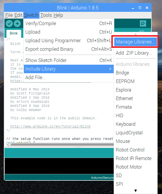
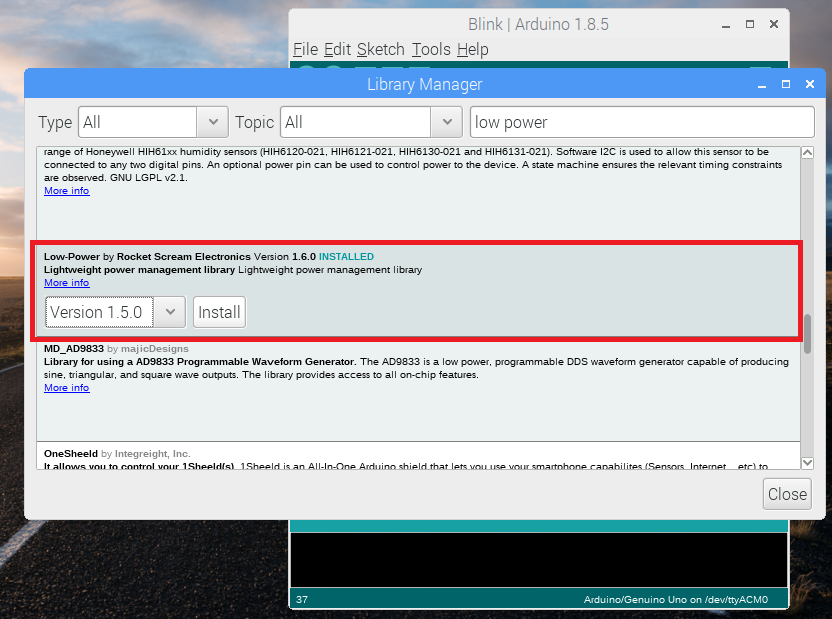
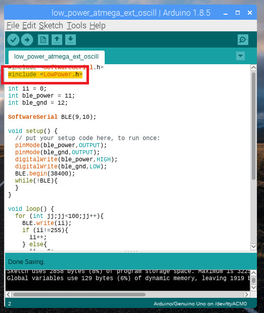
In order to take advantage of the Low Power library, you will need to install it either via the Library Manager or by downloading the library and moving it to your 'libraries' folder in your Arduino sketch folder. The Low Power library can be found here on GitHub. The library is by rocketscream and has a wide range of low-power applications tailored specifically to the ATmega boards. Below I took screenshots for downloading the library via the Library Manager.
If you're interested in learning about the specifics of the library, check out rocketscream's web article that breaks down the power consumption of each sleep cycle (here).
Sleep Routines that Prioritize IoT Efficiency
For our particular case, we are interested in power-down sleep that either routinely wakes up to read data from a sensor or sleeps until an external interrupt is triggered. The sleep current is also dictated by the sensor's quiescent current, so we need to pick sensors that are efficient during inactive moments (for external interrupts) or we will need to program and wire the sensors such that the Arduino controls the power given to the sensor to reduce energy while the ATmega is sleeping.
The low-power library is called as follows:
| Variable | Options |
|---|---|
| POWER STATE | idle, adcNoiseReduction, powerDown, powerSave, powerStandby, powerExtStandby, standby |
| Sleep Period | SLEEP_15MS, SLEEP_30MS...SLEEP_8S, SLEEP_FOREVER |
| Analog-to-Digital Converter | ADC_OFF, ADC_ON |
| Brown-out Detector | BOD_OFF, BOD_ON |
| others | USART0_OFF, USART0_ON, SPI_OFF, SPI_ON, IDLE_0, etc. |
The colored variables can be changed to achieve different levels of sleep, resulting in variable power consumption. The POWER STATE has several modes from 'idle' (700 µA) to 'powerDown' (5 µA). We use 'powerdown' for IoT because we want to maintain the lowest power draw cycle. For the next variable, Sleep Period, the length of sleep ranges from 'SLEEP_ 15MS' to 'SLEEP_FOREVER.' Depending on the situation and the sensor involved, a sleep time may be prescribed. For an interrupt centric setup, the 'SLEEP_FOREVER' option is ideal because it allows the program to maintain low power consumption indefinitely until interupption. For periodic sleeping, the desired resolution of data determines the sleep time, for example the maximum sleep time is 'SLEEP_8S,' so for a long sleep period, this needs to be looped-over multiple times. I demonstrate this below in the example.
As for the other variables Analog-to-Digital Converter,Brown-out Detector, and others - they augment the power consumption based on the bareness of the breadboard Arduino's funcionality. Therefore, if you want to continue using the Analog-to-digital converter - then you may want to keep it running. Or if you want to keep the UART pins available - then you will need to dig into the library and ensure they are operating under your sleep conditions.
A typical condition for our IoT devices may look something like this:
What is given above will result in a powered-down Arduino that will sleep until an external interrupt is triggered. The ADC is off and the brown-out detector is disabled. For the full instructions options, see the library's GitHub here. For a review of the power states and their approximate current consumption, see here.
Putting It All Together - Creating an IoT Node to Measure Temperature

DHT22 Temp/Humidity Sensor
I will be using the DHT22 temperature sensor to periodically read temperature and humidity from the breadboard Arduino. You will need the Adafruit DHTxx library (here), as well as the Adafruit_Sensor library (here). You can also use the Library Manager to download both of these libraries, which will make things easier and quicker. An entire tutorial on DHTxx can be found on Adafruit's website (here). From this point on, it is assumed that you have the DHT library and your sensor has been tested and is functional. Below is a screenshot of the DHT22 printout from the Adafruit Tutorial.

For this particular test, we will also be keeping the crystal frequency at 16 MHz. The DHT22 requires specific timing, so I decided to keep it simple here and stick with the 16 MHz crystal. The wiring diagram is shown below. The HM-10 and DHT22 power pins are both controlled by the Arduino, which means that during sleep periods, they are completely off. This allows the Arduino to sleep at the minimal 5µA. The only caveat to the HM-10 being unpowered during the sleep mode is that it is completely unaddressable. This means that you cannot wake the sensor or control it when the node is sleeping. You can, of course, choose to power the HM-10 during sleep modes, but the sleep mode on the HM-10 draws roughly 500 µA, which isn't worth it in our case. The drawback is that you need to be listening for the Bluetooth module when you want to read - which can be an issue, but I will cover this in another tutorial. For now, I wrote the code to have enough time to connect,read the sensor, and transmit the data.
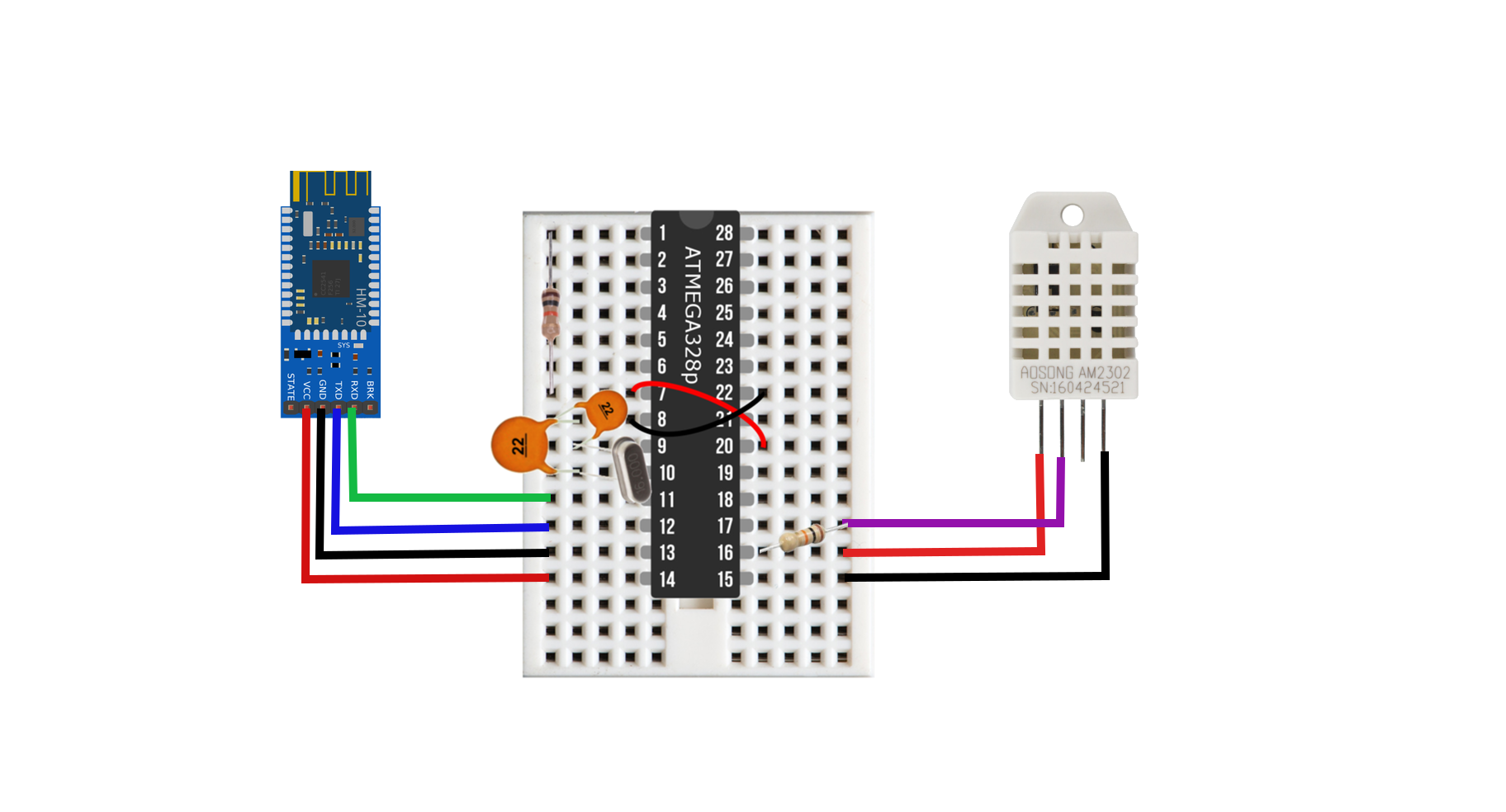
Wiring diagram for the breadboard Arduino DHT22 Bluetooth node. With this wiring configuration, the node is capable of sleeping at micro-amp currents, reading temperature data, and then transmitting it via Bluetooth. Hm-10 module drawing was found here at Arduibots.wordpress.com.
#include <LowPower.h> //low power library
#include "DHT.h" //temperature sensor library
#include <SoftwareSerial.h> //serial communication for bluetooth

#define DHTPIN 11     // what digital pin we're connected to
#define dht_vcc 10    // temp sensor +
#define dht_gnd 9     // temp sensor -

#define ble_vcc 8     //bluetooth +
#define ble_gnd 7     //bluetooth -
#define ble_TX 5      //bluetooth TX
#define ble_RX 6      //bluetooth RX

volatile float hum;
volatile float temp;

// Uncomment whatever type you're using!
//#define DHTTYPE DHT11   // DHT 11
#define DHTTYPE DHT22   // DHT 22  (AM2302), AM2321
//#define DHTTYPE DHT21   // DHT 21 (AM2301)

SoftwareSerial ble(6,5);

// Initialize DHT sensor.
DHT dht(DHTPIN, DHTTYPE);

void setup() {
  pinMode(dht_vcc,OUTPUT);
  pinMode(dht_gnd,OUTPUT);
  digitalWrite(dht_vcc,HIGH);
  digitalWrite(dht_gnd,LOW);

  pinMode(ble_vcc,OUTPUT);
  pinMode(ble_gnd,OUTPUT);
  digitalWrite(ble_vcc,HIGH);
  digitalWrite(ble_gnd,LOW);

  //Serial.begin(9600); //uncomment to compare with serial monitor
  ble.begin(9600);
  dht.begin();
}

void loop() {
  // loop 3 times to get recent temp. There is usually a delay regardless, but this helps
  for(int mm;mm<3;mm++){
    hum = dht.readHumidity(); // humidity
    temp = dht.readTemperature(); // celsius temp
  }
  if (isnan(hum) || isnan(temp)) {
    return; //exit if any issues reading
  }
  // The next few lines help transmit the temperature as two integers:
  //first is the temperature readout, the second is the residual decimals
  int temp_round_int = (int)temp;
  float temp_round_float = (float)temp_round_int;
  int temp_residual = (int)((temp-temp_round_float)*100);
  pinMode(ble_gnd,OUTPUT); // turn on bluetooth again
  delay(8000); // delay to allow reading
  ble.write(temp_round_int); // write temp to smartphone
  delay(200);
  ble.write(temp_residual);
  delay(500); // wait for transmission
  //Serial.println(temp); /uncomment for serial printing
  delay(100);
  pinMode(ble_gnd,INPUT); //turn bluetooth off again before sleep
  pinMode(dht_gnd,INPUT);
  LowPower.powerDown(SLEEP_8S, ADC_OFF, BOD_OFF);
  delay(100);
  pinMode(dht_gnd,OUTPUT);
}
The configuration above consumes:
- 18 mA during active mode
- 5.1 µA during sleep mode
The duty cycle is roughly 55%, so you get roughly a 9 mA average current. This results in over 2 days of constant readings every 8 seconds with a 500 mAh battery. If you increase the sleep time to half an hour (instead of 8 s, which is a more realistic read interval), you end up with 48 readings in a day, which means a 500 mAh battery will last around 7 months. This calculation does not factor in battery trickle, current spikes, etc. - but it is impressive nonetheless!
iOS App to Receive the Data

BLE Scanner 4.0 iOS App
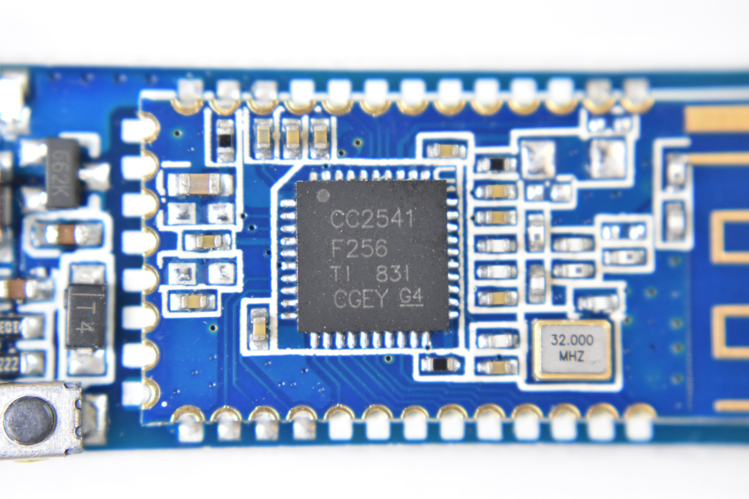
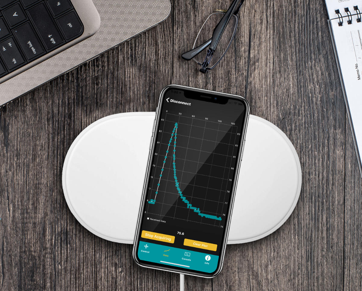
In order to receive the data, I use the BLE Scanner 4.0 app from the iOS app store (here is a link). While scanning for the HM-10, you will notice several devices showing up. The HM-10 should be called 'HMSoft' or 'CC2541.' It is possible that another name will show up, if you programmed the HM-10 via AT-commands and changed its name via 'AT+NAMExxxx.' Once you have selected the HM-10 module, you will be able to communicate via Bluetooth and receive the data you programmed above! The screenshot below shows how the data will be transmitted to the smartphone. It should come in two, the first being the primary temperature, and the second being the decimal value. For example, in the screenshot, the temperature at the time was 26.7 degrees.

NOTE: This method of keeping the sensor awake and reading via a Bluetooth Scanning App is not an advisable way of creating an Internet of Things, however, it is a great starting point for testing sensors, algorithms, and communication. It may seem like a tedious exercise to catch the Arduino when it is awake, but it's the simplest alternative to writing an iOS app, sending data to a main hub (Raspberry Pi), or worrying about WiFi and third-party APIs.
Conclusion
This tutorial took the Arduino Internet of Things tutorial (see part one here, if you haven't already) one step further by transforming the breadboard Arduino into a connected device. In our case, Bluetooth was used to communicate to a smartphone and send temperature readings. I also explored the effect of crystal frequency on the active power consumption and the effectiveness of deep sleep routines. The low power Arduino library shows that the breadboard Arduino is capable of running for months, even years by small rechargeable battery. With the proper coding techniques and efficient sensors, I showed you how to create an IoT Bluetooth temperature sensor using the DHT22, HM-10 Bluetooth module, low-power library, and breadboard Arduino. The multimeter readouts showed that with the routines and modules above, we can create a Bluetooth temperature sensor that reads 48 readings per day for around 8 months (on a 500 mAh battery). In the next installment of the Arduino Internet of Things tutorial series, I will cover how to create an interrupt node with a motion sensor, which will open up several avenues for possible applications. Click here or below for Part 3.
Products in our Shop relevant to this project:

The Atmega328P is at the center of every Arduino Uno board and acts as the 8-bit microcontroller that controls and interacts with sensors, motors, relays, and other electronic devices. The ATmega328P-U shown here is a dual in-line package microchip that can be placed on a breadboard, making it ideal for projects that require enclosure, or prototypes moving beyond the development board phase. The ATmega328P-U is also a great selection for Internet of Things (IoT) development, as its inherent power consumption is very low without LEDs or regulators.
Included in the ATmega328P-U Package:
1x ATmega328P-U with Arduino Bootloader
Some Features of the ATmega328P-U:
28-Pins in a Dual In-Line Packaging (2x14 pins)
Capabilities: SPI, I2C, USART, PWM
2.7V - 5.5V Input Voltage Range
1µA - 1.5mA Power Consumption (3V)
10-bit Analog-to-Digital Converter (8-channels)
Interrupt Capabilities (2-channel)
32KB of Flash Memory for Programming
0MHz-16MHz Frequency Capabilities (External Crystals)
8-bit/16-bit Timers
Compatible with Arduino IDE
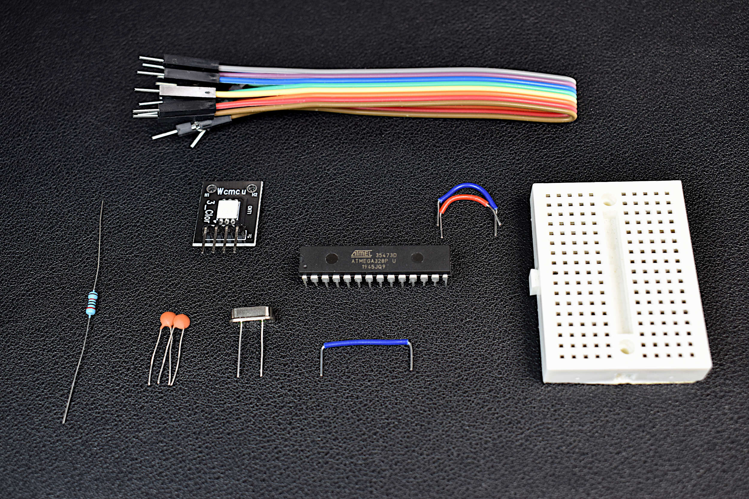
An Arduino board is a collection of electronic components that enable users to rapidly prototype with a central microcontroller. LEDs, regulators, and fixtures make getting started with the Arduino platform simple. This DIY Arduino kit aims to demystify the Arduino board by taking the essential components of an Arduino board and putting them into one kit. The DIY Arduino kit uses an ATmega328P-U as the central microcontroller, and some essential electronic components necessary to function as an Arduino board.
Included in the DIY Arduino Kit:
1x ATmega328P-U Microcontroller
1x 16MHz Quartz Crystal Oscillator
2x 22pf Capacitors
1x 20kOhm Resistor
1x RGB LED
1x Mini Breadboard
10x Jumper Wires
Included in the DIY Arduino Kit + Uno Board:
Everything Above + Arduino Uno Rev3 Board for Programming the DIY Board
Some Features of the DIY Arduino Kit:
Fully-Functional Arduino Board
Low Power Consumption due to lack of LEDs or Regulators
Arduino Already Bootloaded onto the ATmega328P
Low Profile Breadboard, smaller than an Arduino Uno board
RGB LED for testing code
2.7V - 5.5V Operating Range
5µA Low Current when Powered Down (3.3V, 16MHz)
8mA Working Current (3.3V, 16MHz)
Jumper Wires for Uploading Code, and Interacting with Sensors and Motors
Some Features of the ATmega328P-U Chip:
28-Pins in a Dual In-Line Packaging (2x14 pins)
Capabilities: SPI, I2C, USART, PWM
2.7V - 5.5V Input Voltage Range
1µA - 1.5mA Power Consumption (3V, 4MHz)
10-bit Analog-to-Digital Converter (8-channels)
Interrupt Capabilities (2-channel)
32KB of Flash Memory for Programming
0MHz-16MHz Frequency Capabilities (External Crystals)
8-bit/16-bit Timers
Compatible with Arduino IDE

3.7V LiPo batteries are useful for low-power Arduino IoT applications. The 600mAh battery shown here can power a standard Arduino Uno board for a few days under moderate processing conditions, and up to several months with the right sleep routines and modifications (power down, no LED, etc.)!
Included in the LiPo Battery Kit for Arduino:
1x 600mAh LiPo Battery
1x USB Charger
1x JST to DuPont Connector (For Wiring to Arduino)
Features of the 3.7V LiPo Battery Kit for Arduino:
600mAh LiPo Battery with USB Charger
3.7V Battery Voltage
JST connector for direct wiring to Arduino