Arduino Internet of Things Part 1: Burning The Arduino Bootloader Onto A Blank ATmega328p Chip Using The Arduino Uno
This is the first of several Internet of Things (IoT) tutorials using the ATmega328p board. I chose the ATmega328p board because of its ubiquity in the Arduino maker electronics community, and the low-power consumption and efficiency of the chip. In this tutorial, I discuss the parts needed to make a $3 DIY Arduino board, how to wire that board, how to load the Arduino bootloader onto the ATmega chip, and how to upload a sketch onto the 'breadboard Arduino' to simulate an Arduino Uno environment. Since this is the first of the series, I chose only to discuss the parts and how to go from a blank ATmega chip to a working Arduino board. The next tutorial in the series will continue by optimizing that minimal breadboard Arduino to investigate power consumption and sleep cycles. The primary goal of this tutorial is to create a framework for a low-power, connected, versatile board that can be tailored to specific IoT applications.
Parts List and Breadboard Wiring
The Arduino IoT board is a simple collection of essential parts that exist on a given Arduino Uno board. The parts list mirrors the components used to follow exactly along with the tutorial:
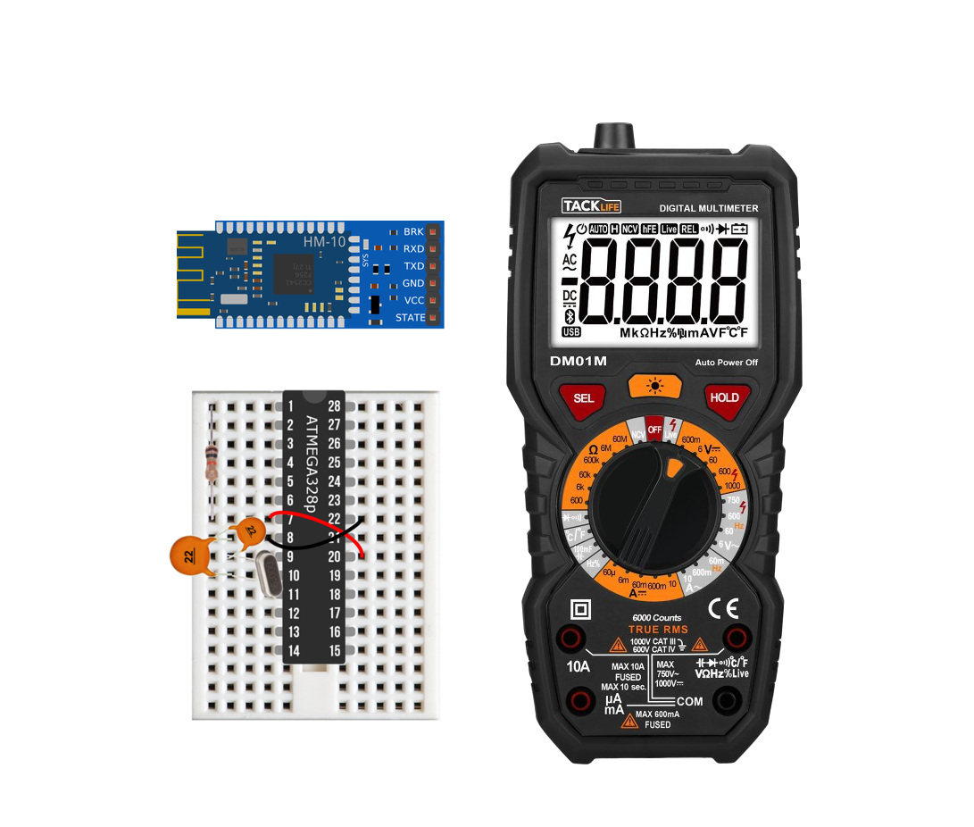
ATmega328P-PU Chip - $23.99 (10pcs) [Amazon], $15.99 (4 pcs) [Amazon]
22pf Capacitors - $16.99 (600pcs, various) [Amazon], $4.69 (25pcs) [Amazon]
16MHz Quartz Crystal Oscillator - $3.00 (10pcs) [Amazon], $15.99 (200pcs, various) [Amazon]
10k Resistor - $5.99 (100 pcs) [Amazon], $14.99 (1280pcs, various) [Amazon]
Arduino Uno Board - $11.00 [Our Store]
Mini Breadboard - $3.00 [Our Store]
Average Cost for DIY Board: ≈ $2.95

The Maker Portal Uno board is the centerpiece of many of the projects carried out in our maker spaces. The Uno board is capable of reading a wide range of sensors using analog-to-digital conversion, SPI, I2C, UART, and other common protocols. The Uno board can be used to control motors, OLED/LCD displays, and LEDs. The Arduino Uno board shown here is the official Maker Portal microcontroller, which we use in many of our projects!
Included in the Arduino Uno Package:
Maker Portal Arduino Uno Rev3 Board
Black USB Cable (1m in Length)
Specifications for Arduino Uno Rev3 Board:
ATmega328P chip with Arduino Bootloader
14 digital pins, 6 analog pins
10-bit analog-to-digital converter (ADC)
5V-12V Supply Tolerance
3.3V and 5.0V output pins
16 MHz clock
5 PWM pins, I2C support, SPI support , UART support
ATmega16U2 USB TTL, compatible with Linux, Windows, and Mac
Black Stylish Finish
Fully Integrated with Arduino IDE software
IMPORTANT NOTE: You can find Arduino Uno boards online for around $3-$5 from AliExpress. However, we are not building a simple arduino board, we are creating an IoT node. The cheap $3-$5 boards are too large, sink too much power, and are simply unnecessary. The goal of IoT is to create tiny sensor nodes that are efficient and sleek. You may also find Arduino Pro Mini boards out there for around $2. Those are much closer to what we are building, with the exception of the crystal oscillator and power requirement. We want to lower the crystal oscillating frequency (from 16MHz to 8/4 MHz) and also use LiPo batteries at 3.7V or even lower. Both of these adjustments make the nodes very low power, yet still function with Bluetooth modules. There is an 8MHz board out there (AliExpress) for about $4, which could suffice, but I recommend removing the onboard LED to lower the consumption, and again acknowledge the inability to lower the crystal frequency from 8MHz to 4MHz (without de-soldering).

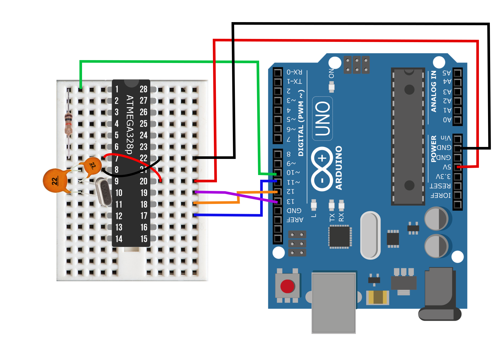
Figure 1: Component wiring diagram consisting of the dual 22 pf capacitors, 16 MHz crystal oscillator, 10 kOhm resistor, and ATmega328p chip. These components create a low-cost Arduino board that will be integrated into the Internet of Things (IoT). The total component cost is less than $3.

Figure 2: Minimal ATmega328p Arduino
Figures 2 and 3 show the component setup for the minimal Arduino board. The primary reason for the capacitors is to moderate the oscillations from the crystal oscillator. With the inclusion of the crystal oscillator allows us to keep accurate timing, which will in turn permit the use of Bluetooth modules via serial communication - an essential for IoT integration. Here we use a 16 MHz crystal oscillator, which is necessary to upload the Arduino bootloader. Once the bootloader is uploaded, other oscillators can be used to lower the power consumption of the minimal board.
Uploading ArduinoISP to Uno Board
Since we will be using an Uno board to program ATmega328 chips, we need to upload the ArduinoISP sketch to the Uno board before wiring anything together. The steps below should be followed to upload the ArduinoISP sketch.
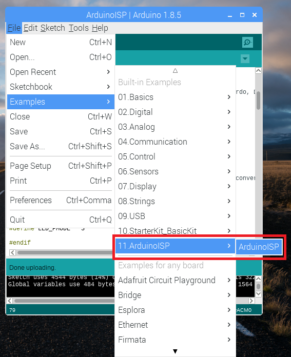
- Select ArduinoISP under Examples->ArduinoISP
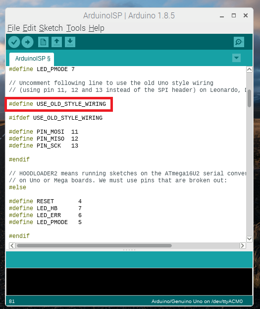
- Uncomment '#define USE_OLD_STYLE_WIRING
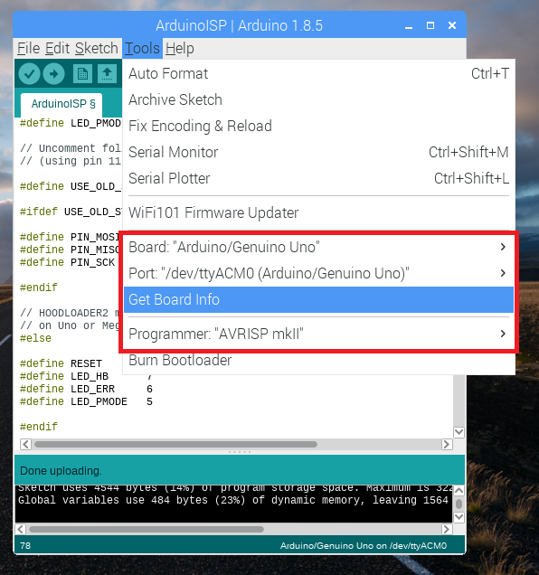
- Make sure that Arduino Uno board is selected
- Upload sketch to Arduino Uno board (nothing wired to it)
See below for screenshots of procedure:
Now that the ArduinoISP sketch is wired to the Uno board, it is time to wire the breadboard Arduino to the Uno board. This will prep the Arduino Uno as ISP and allow one to upload the Arduino bootloader to the ATmega328 on the breadboard.
Wiring and Bootloading The External ATmega Board
The ATmega on the breadboard should be wired to the Uno as shown in the table and image below:
| Arduino Uno | ATmega Breadboard (pin) |
|---|---|
| 5V | 20 |
| GND | 22 |
| D10 | 1 |
| D11 | 17 |
| D12 | 18 |
| D13 | 19 |

Figure 3: Arduino Uno as ISP wiring diagram for burning the Arduino bootloader to the ATmega breadboard.
Now, in the Arduino IDE the Programmer needs to be set as 'Arduion as ISP' to upload the bootloader to the ATmega chip.
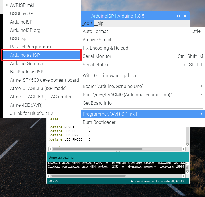
Finally, once the ATmega is wired to the Arduino Uno and the Programmer is switched to 'Arduino as ISP,' click 'Burn Bootloader' to burn the Arduino bootloader. This process uses the Uno board as an in-circuit serial programmer (ISP) to program the ATmega328p chip as an Arduino board. Once this is done, one can treat the ATmega on the breadboard as a classic Arduino board. In the next section, I cover the simple process of uploading a sketch to the breadboard Arduino.
Uploading a Sketch to ATmega Breadboard Arduino
At this point, the ATmega configuration is an Arduino board! But in order to upload sketches to the chip we need to remove the main chip from the Uno board. This allows the Uno to bypass its chip and serially communicate sketches to the breadboard Arduino via the TX/RX pins. Below is the wiring diagram and table for uploading sketches to the breadboard Arduino.
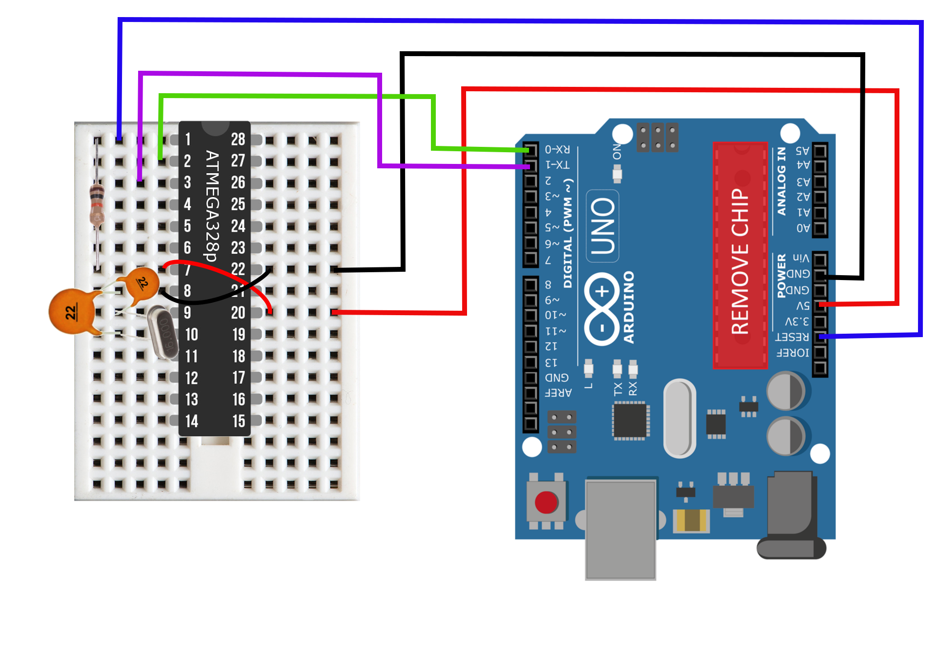
Figure 4: Wiring diagram for uploading a sketch to the ATmega breadboard. Notice the removed ATmega328p chip from the Uno board - this is necessary to bypass the chip and upload sketches to the off-board chip located on the breadboard.
| Arduino Uno | ATmega Breadboard (pin) |
|---|---|
| 5V | 20 |
| GND | 22 |
| RESET | 1 |
| D0 (RX) | 2 |
| D1 (TX) | 3 |
It is a good idea to upload a simple sketch and ensure the breadboard Arduino is functioning properly. An external LED blink sketch is a good sketch to start with, or even an analog read/write sketch to test that the bootloader has been burned correctly.
Conclusion
This tutorial covered the basics of wiring and flashing a low-cost ATmega328p chip using an Arduino Uno board. It is the first entry into a series of tutorials designed to create and test a network of sensors and smart devices that communicate via Bluetooth and operate for months on a single LiPo battery charge. The framework shown above is the hardware basis that will allow the user to control both the communication via Bluetooth and power consumption through software implementation. The ATmega-based breadboard Arduino can read temperature and humidity sensors, it is capable of registering interrupts via hall sensors or motion sensors; the framwork is also able to read analog signals at 10-bit resolution, and can do almost everything a typical Arduino Uno can - with the exception of certain power limitations depending on the components used. The following tutorial will explore power consumption and methods to optimize the sleep cycles of the breadboard Arduino.