Arduino Internet of Things Part 3: External Interrupts Using A Motion Sensor (HC-SR501)
This is the third entry into the Arduino Internet of Things tutorial series. In this installment, I will cover interrupts from passive infrared (PIR) motion sensors using the low-power library discussed in Part 2. If you missed Part 1 or Part 2, please click the links to read through those and ensure you are up to speed with the current tutorial. I will be using the 4 MHz crystal here to lower the consumption of the active breadboard Arduino and optimize battery life. I will also introduce the Raspberry Pi as a Bluetooth receiver and IoT hub to record the data transmitted by the Arduino nodes. This entry will bridge the gap between connected nodes and an Internet of Things.
Parts and Wiring for Motion Detection
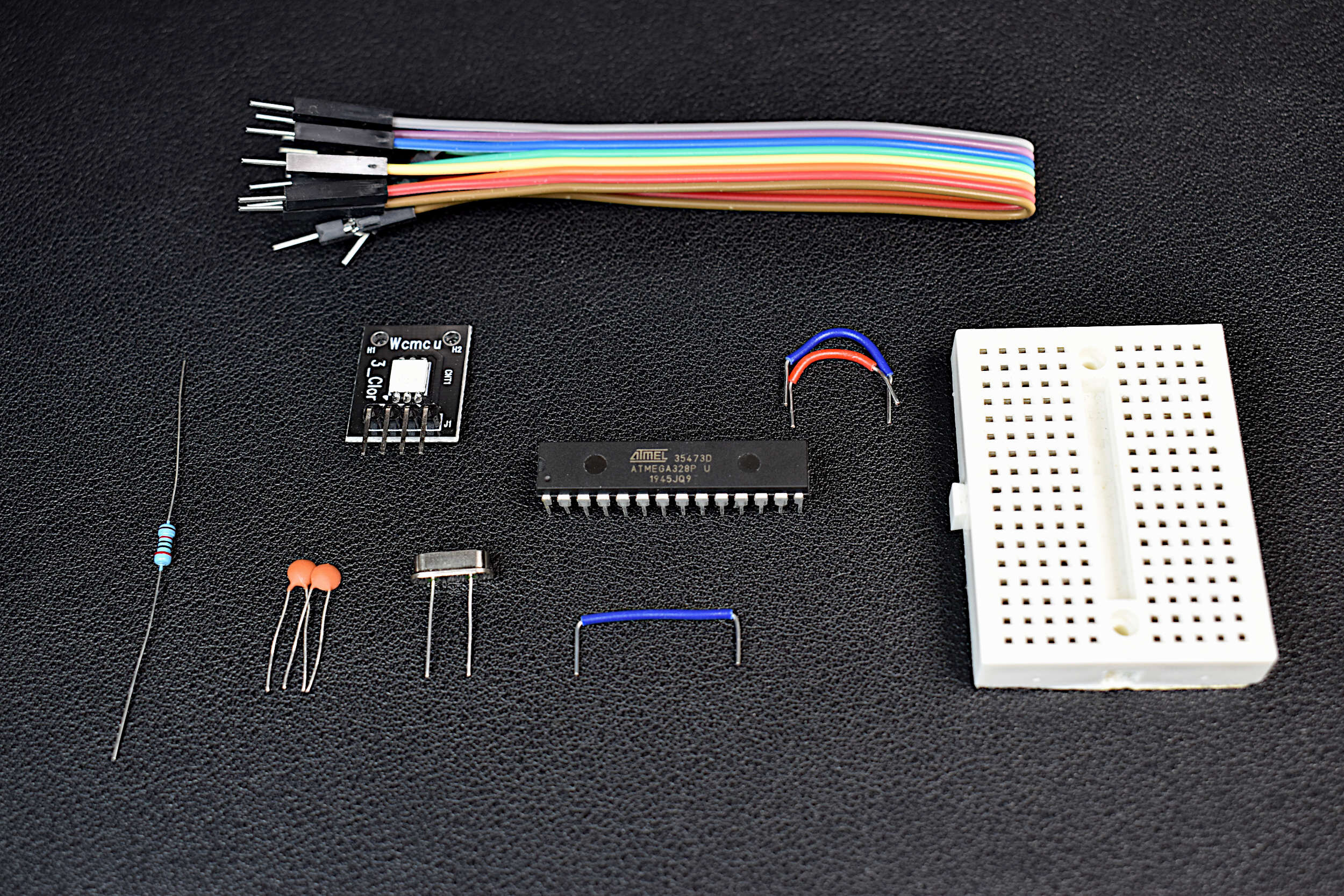
An Arduino board is a collection of electronic components that enable users to rapidly prototype with a central microcontroller. LEDs, regulators, and fixtures make getting started with the Arduino platform simple. This DIY Arduino kit aims to demystify the Arduino board by taking the essential components of an Arduino board and putting them into one kit. The DIY Arduino kit uses an ATmega328P-U as the central microcontroller, and some essential electronic components necessary to function as an Arduino board.
Included in the DIY Arduino Kit:
1x ATmega328P-U Microcontroller
1x 16MHz Quartz Crystal Oscillator
2x 22pf Capacitors
1x 20kOhm Resistor
1x RGB LED
1x Mini Breadboard
10x Jumper Wires
Included in the DIY Arduino Kit + Uno Board:
Everything Above + Arduino Uno Rev3 Board for Programming the DIY Board
Some Features of the DIY Arduino Kit:
Fully-Functional Arduino Board
Low Power Consumption due to lack of LEDs or Regulators
Arduino Already Bootloaded onto the ATmega328P
Low Profile Breadboard, smaller than an Arduino Uno board
RGB LED for testing code
2.7V - 5.5V Operating Range
5µA Low Current when Powered Down (3.3V, 16MHz)
8mA Working Current (3.3V, 16MHz)
Jumper Wires for Uploading Code, and Interacting with Sensors and Motors
Some Features of the ATmega328P-U Chip:
28-Pins in a Dual In-Line Packaging (2x14 pins)
Capabilities: SPI, I2C, USART, PWM
2.7V - 5.5V Input Voltage Range
1µA - 1.5mA Power Consumption (3V, 4MHz)
10-bit Analog-to-Digital Converter (8-channels)
Interrupt Capabilities (2-channel)
32KB of Flash Memory for Programming
0MHz-16MHz Frequency Capabilities (External Crystals)
8-bit/16-bit Timers
Compatible with Arduino IDE

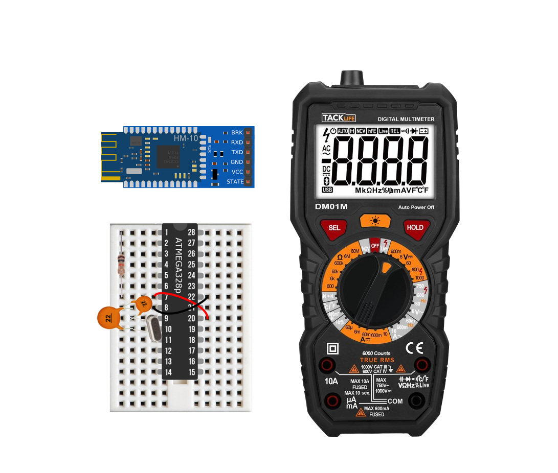
HC-SR501 PIR Sensor
PIR sensors are widely used as motion detectors because they passively focus (through optics) infrared radiation given off by human body heat, which allows the sensors to work with very little power supplied. The quiescent current for the PIR used here (HC-SR501) is only about 55 microamps. This, in conjunction with the low cost of these sensors, makes PIR detectors ideal for IoT applications in smart homes and remote security systems.
Wiring:
The important thing to remember when wiring the HC-SR501 is that the sensor is passive and sends only high or low data to the Arduino. Therefore, it is imperative that we put a resistor on the data pin (to lower the current draw) and ensure that the data pin is wired to one of the external interrupt pins (see ATmega328P pinout below).

ATmega328P Pinout
We will be using the external interrupt pins which are labeled INT0 and INT1 in pink (D2/D3 in IDE code)
[image courtesy of: doolox.com]
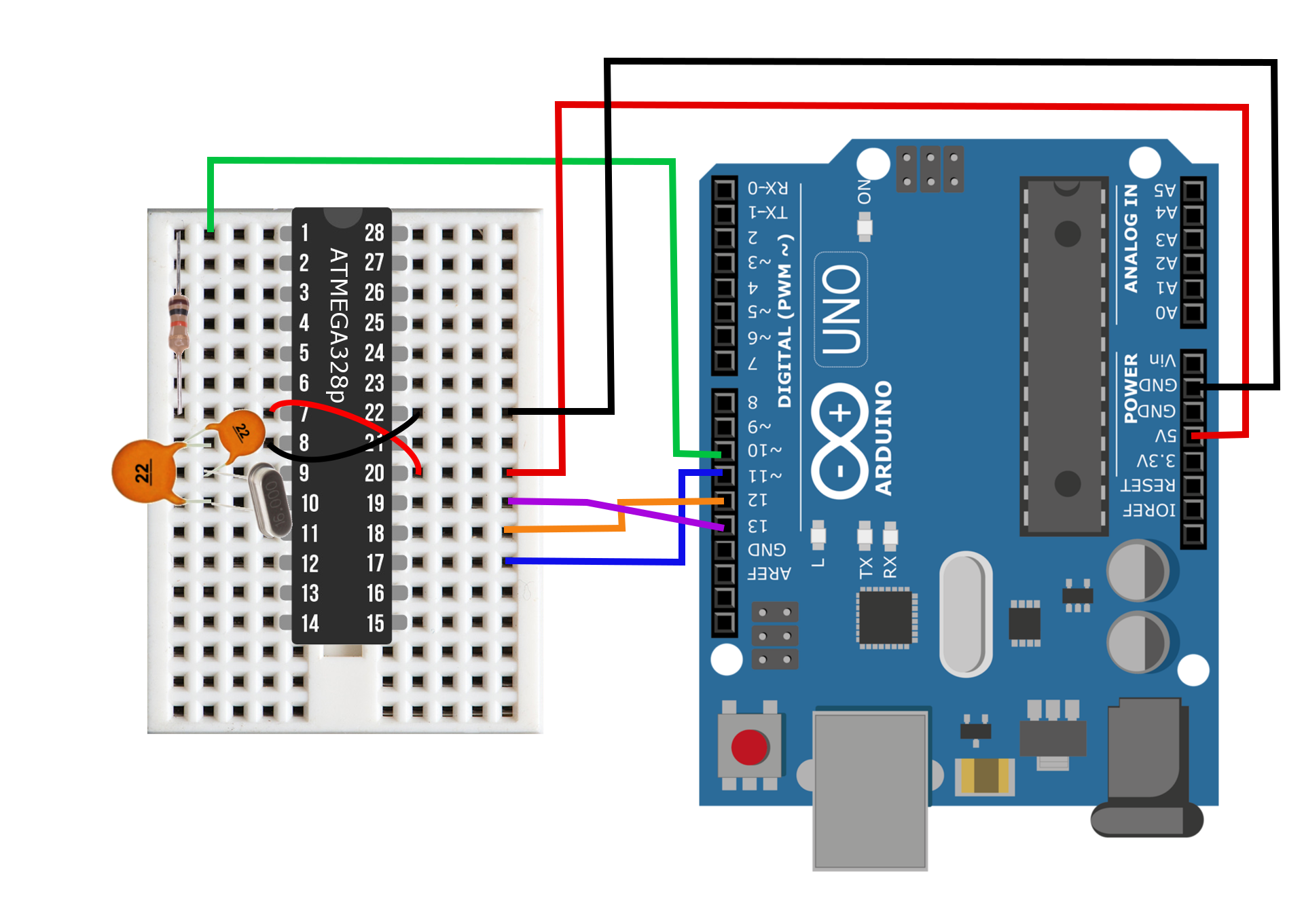
We will again be wiring the breadboard Arduino to the HM-10 and a LiPo battery. The HC-SR501 is a simple addition to the wiring diagram (see below), and requires only a resistor between the data pin and the interrupt pin. It is also wired directly to the positive and negative terminals of the Arduino - so we will not be controlling the power in this case (like the DHT22 node), since the PIR needs to be powered continuously to enable interrupts.

External Interrupt Process Flow and Code
Now that the motion detector is wired to function as a standalone, Bluetooth-enabled, IoT node, we need to ensure that the following process loop is maintained when programming the Arduino:

Interrupt Process Flow
In order to achieve low-power consumption, the device needs to be at its lowest power state (sleep) as much as possible. Therefore, it is imperative that the process flow moves through the detection and notification process as fast as possible in order to return to sleep.
In the previous tutorial I covered powering on, sending data, and powering down the Bluetooth module programmatically in Arduino; so I won't cover those processes here again. And since the PIR is binary when detecting motion, we only need to worry about programming the sleep and wake routines. Thankfully, the low-power library handles external interrupts nicely- so we will be using its 'SLEEP_FOREVER' mode to sleep until the PIR trips an interrupt pin. The table below from the Arduino website outlines the interrupt pins on each Arduino board. For our breadboard Arduino, we can use pin D2 or D3.
| BOARD | DIGITAL PINS USABLE FOR INTERRUPTS |
|---|---|
| Uno, Nano, Mini, other 328-based | 2, 3 |
| Mega, Mega2560, MegaADK | 2, 3, 18, 19, 20, 21 |
| Micro, Leonardo, other 32u4-based | 0, 1, 2, 3, 7 |
| Zero | all digital pins, except 4 |
| MKR1000 Rev.1 | 0, 1, 4, 5, 6, 7, 8, 9, A1, A2 |
| Due | all digital pins |
| 101 | all digital pins (Only pins 2, 5, 7, 8, 10, 11, 12, 13 work with CHANGE) |
When programming an interrupt, there are five key lines of code:
- Program interrupt pin - pinMode(interrupt_pin,INPUT)
- Attach Interrupt - attachInterrupt(digitalPinToInterrupt(interrupt_pin), wake_routine, mode)
- Sleep and Wait for Interrupt - LowerPower.powerDown(SLEEP_FOREVER,ADC_OFF,BOD_OFF)
- Detach Interrupt - detachInterrupt(digitalPinToInterrupt(interrupt_pin))
- -- Wake Routine --
These five processes allow the Arduino to run on a single battery for months at a time by sleeping at very low power while also listening for external interrupts. The code below shows the Arduino interrupt routine implemented for the HC-SR501 motion sensor:
#include <LowPower.h> //low power library
#include <SoftwareSerial.h> //serial communication for bluetooth

#define interrupt_pin 2     // interrupt pin

#define ble_vcc 8     //bluetooth +
#define ble_gnd 7     //bluetooth -
#define ble_TX 5      //bluetooth TX
#define ble_RX 6      //bluetooth RX

SoftwareSerial ble(6,5);

void setup() {

  pinMode(interrupt_pin,INPUT);

  pinMode(ble_vcc,OUTPUT);
  pinMode(ble_gnd,OUTPUT);
  digitalWrite(ble_vcc,HIGH);
  digitalWrite(ble_gnd,LOW);

  //Serial.begin(9600); // uncomment if you want to read through serial port
  ble.begin(38400); // for 4 MHz crystal use 38400 // for 16 MHz crystal use 9600
}

void loop() {
  // Initiate (attach) interrupt, sleep, and wait for motion sensor to trip

  attachInterrupt(digitalPinToInterrupt(interrupt_pin),wake_routine,RISING);
  LowPower.powerDown(SLEEP_FOREVER, ADC_OFF, BOD_OFF); // sleep until interrupt
  detachInterrupt(digitalPinToInterrupt(interrupt_pin)); //stop interrupt to allow program to run
  // All delays need to be multiplied by the ratio of crystal speed. The numbers below are for 4 MHz
  delay(25);
  //Serial.println("MOTION"); // notify through serial port
  pinMode(ble_gnd,OUTPUT); // turn on bluetooth again
  delay(2000); // delay to allow reading
  ble.write("m"); // write temp to smartphone
  delay(50);
  pinMode(ble_gnd,INPUT); // disable bluetooth
  delay(50);
}

// dummy routine for interrupt
void wake_routine(){
}
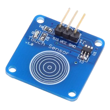
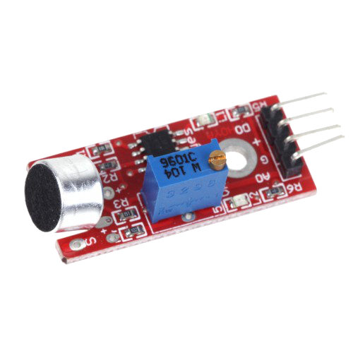
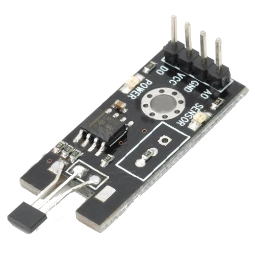
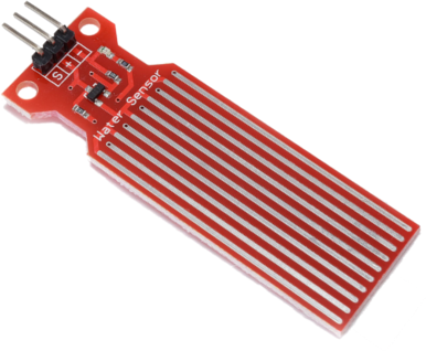
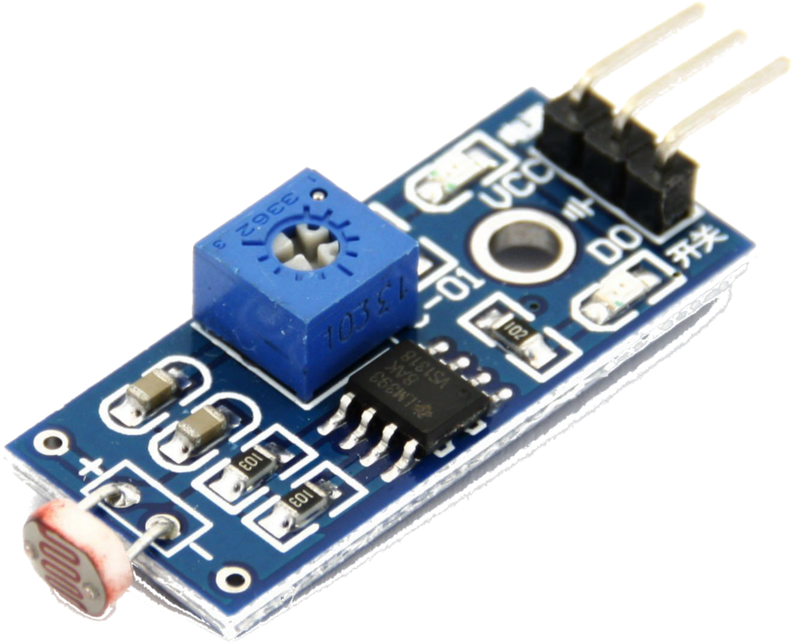
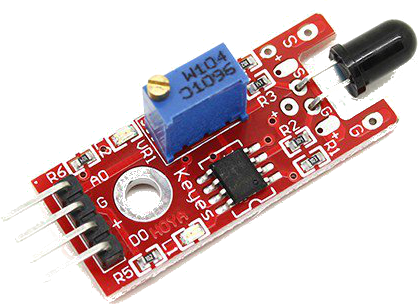
The most important thing to remember with the code above is that it is an interrupt code, which means that it will work for any situation where the interrupt pin's state changes. The state change could occur because of a magnetic hall sensor, water level detector, reed switch, photoresistor, capacitive touch sensor, microphone - there are many possibilities. That is the advantage of low-power interrupts with Arduino: any sensor can cause an interrupt as long as the circuit is wired appropriately.
Interrupt Sensor Examples
Conclusion
In this third entry into Arduino Internet of Things tutorial series I covered interrupts and how to program the breadboard Arduino to sleep until an external interrupt is tripped. Interrupts are paramount to smart homes and intelligent security systems because of their reliability, efficiency, and simplicity. Motion sensors, light sensors, entry sensors (hall effect), and water level sensors are all types of interrupt devices that utilize deep sleep cycles to lower power consumption when not active. Here I showed how to wire and code an IoT node that wakes from a deep sleep, sends a notification via Bluetooth, and then sleep indefinitely until another interrupt is triggered. This third installment marks the end of the hardware side of the Arduino IoT series, and I will now focus on the receiving side of the connected devices. Now that we have the capability of several nodes (temperature sensor, motion sensor, hall effect sensor), we can investigate how to connect them all and produce a smart hub system that uses Raspberry Pi to collect the data from the nodes and create a connected Internet of Things.