ESP8266 WiFi Module - Flashing with Arduino Uno and Smart Home Web Server LED Blink
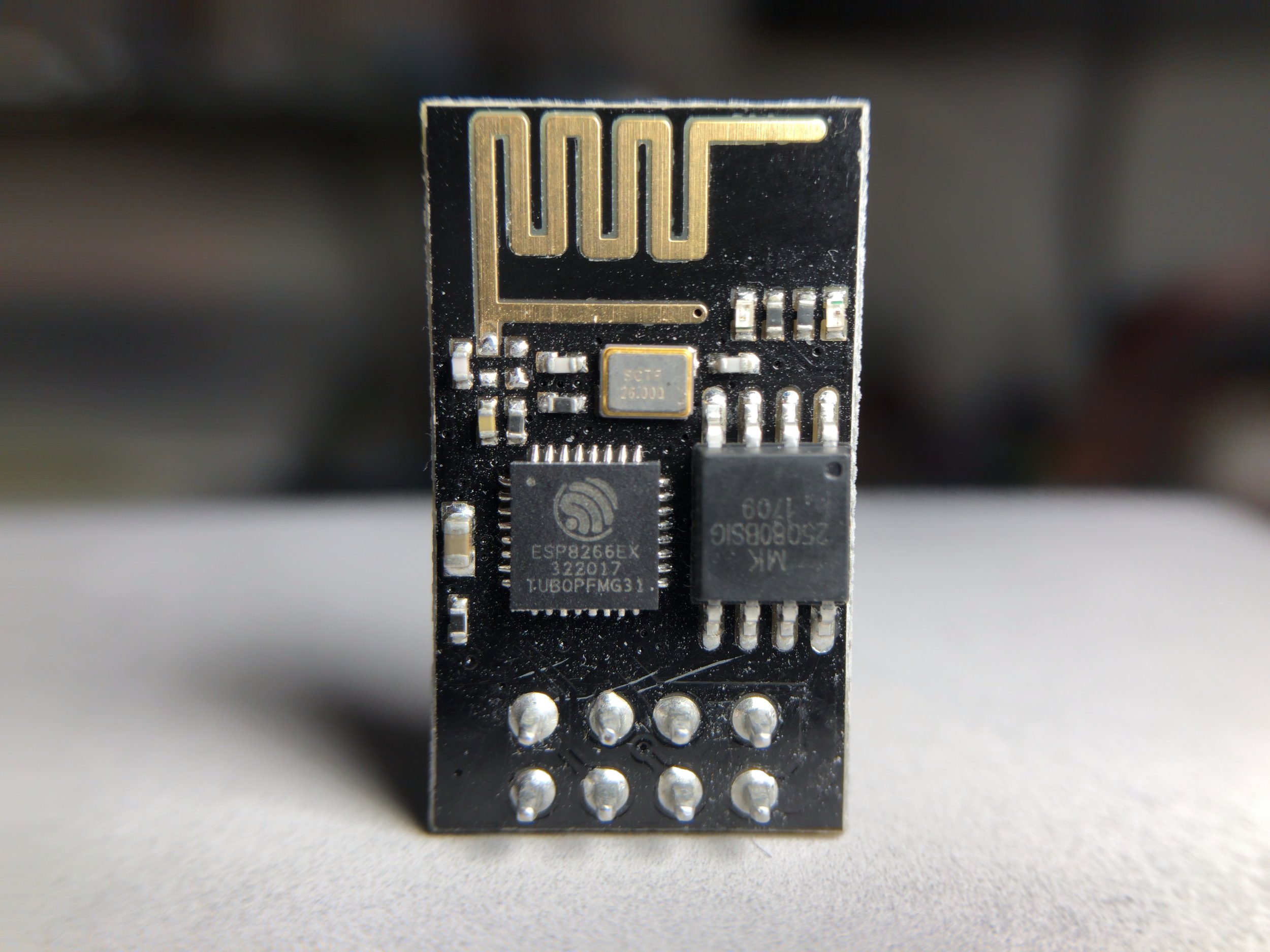
Figure 1: ESP8266 module with 8 breakout pins. This module is just over $3 when bought in a 4-pack, and even cheaper at times.
The ESP8266 is an inexpensive WiFi module that enables makers and entrepreneurs to develop low-cost electronics for integration into the Internet of Things (IoT). Designed by Espressif Systems (see their datasheet for the module here), the ESP8266 is targeted towards the open-source market, which has resulted in an active and mature assemblage of resources. I decided to explore the ESP8266 myself - and I too learned what a bountiful well of information exists on the device. Here, I cover the basics of using the ESP8266 and how to go from unboxing the component to flashing it with the Arduino Uno, and then uploading a sketch that flashes an external LED. This tutorial will be the first of several on using the ESP8266 and taking advantage of its affordability to create IoT devices such as temperature readers, wireless motor controllers, HTTP servers, and much more!
I tried to make this project as maker friendly as possible. As such, I have chosen the Arduino Uno as the flashing component and a few simple LEDs to blink. The parts list is shown below, as well as the links to the components I used and recommend.
Wiring The ESP8266 and Arduino Uno
The first, and perhaps most important, thing to remember is that the ESP8266 will essentially be acting as the Arduino's microchip. Therefore, the ATmega328 needs to be removed from the Arduino board. Figure 2 shows where to remove the chip from. Once the chip is removed, follow the wiring procedure for flashing the ESP module below.

Figure 2: Remove the ATmega328 from the Arduino Uno board to bypass the module and let the ESP8266 act as the central chip. This is essential for flashing the ESP8266 with the Arduino firmware.

Figure 3: Wiring to Program
ESP8266 (Pin) | Arduino Uno (Pin)
1| GND
2| TX (1)
3| ------
4| 3.3V
5| GND
6| ------
7| RX (0)
8| 3.3V
Figure 3 above shows the wiring procedure for flashing and programming the ESP8266. This wiring configuration must be followed when uploading sketches to the ESP8266, along with removal of the ATmega328. In the next section, I will demonstrate how to include the ESP8266 package index in the Arduino IDE and how to setup the IDE for flashing the ESP module.
The full Arduino ESP8266 package is located on GitHub:
There, you can find information regarding documentation, licensing and credits, and all of the build tools needed to run the ESP8266 on the Arduino platform. The most important thing to note is the Boards Manager link:
- Open the Arduino IDE
- File
- Preferences
- Enter http://arduino.esp8266.com/stable/package_esp8266com_index.json into 'Additional Boards Manager URLs'
- Click OK

Figure 4: Pasting the boards manager link
At this point, the ESP8266 should be wired to the Arduino, the ATmega328 should be removed, and the ESP8266 board library should be installed. We now want to configure the board and its parameters to ensure it is working properly. We need to enter the Tools -> Board: menu to change the board to Generic ESP8266 Module. This will ensure that the correct bootloader and code will be uploaded to the ESP. I have also taken a screenshot of this:

Figure 5: Board change from Uno to Generic ESP8266 Module
After selecting the Generic ESP8266 Module from the dropdown menu, you should see the following parameters in the tools menu:

Figure 6: Be sure that all of the parameters above match on your Arduino . I also want to note that some of the newer ESP8266 modules are capable of supporting 1M of flash, as opposed to the Flash Size: "512K (64L SPIFFS)" shown here. You may want to upgrade your flash size, if desired. We only come within 60% of the flash limit, so it's not much to worry about here.
NOTE: Perhaps one of the most notable issues that people have with the ESP8266 flash process on the Arduino is that they forget to enter 'BOOT MODE.' This means that when uploading sketches (flashing) the ESP8266, it is necessary to reset the system (either with a button or simply by unplugging the power or ground) seconds before uploading the sketch. This is MUST be done within seconds of uploading the sketch or you will get an error.
Now, you are capable of uploading a sketch to your ESP8266. You may want to start with one of the simple examples from the ESP8266 library, or continue reading to see how to create an html button that turns an LED on and off.
LED Smart Home on The ESP8266 Web Server
The code outlined below can be found in full at this link here. The code is based off of the work done by bbx10 user on GitHub, and their template can be found here. In short, we are creating a web server with the ESP8266 and using a simple HTML toggle button to turn an LED on and off by using the POST method. If you're not familiar with the HTML, then disregard that code and just focus on the Arduino server-side programming.
The first lines of code below are called for the purposes of creating a web server. So a lot of the work is done on the C++ side of things and they're not too important here. The html_code[ ] should be filled in by the code linked above (and also here).
#include <ESP8266WiFi.h>
#include <WiFiClient.h>
#include <ESP8266WebServer.h>
#include <ESP8266mDNS.h>

const char* ssid = "ssid";
const char* password = "ssid_pwd";

const int GPIO_1 = 0;

char html_code[] =
The next lines are the core of the web server, they outline the setup and loop handling of the ESP8266. Much of the setup involves waiting for the ESP8266 to connect to the local WiFi (via the ssid and ssid_pwd above), and it returns the local IP address of the ESP8266 and prints it on the Serial Port. Therefore, when trying to connect to the web server, you should first find the IP address on the Arduino Serial Port.
void setup(void){
  pinMode(led, OUTPUT);
  digitalWrite(led, 0);
  Serial.begin(115200);
  WiFi.begin(ssid, password);
  Serial.println("");

  // Wait for connection
  while (WiFi.status() != WL_CONNECTED) {
    delay(500);
    Serial.print(".");
  }
  Serial.println("");
  Serial.print("Connected to ");
  Serial.println(ssid);
  Serial.print("IP address: ");
  Serial.println(WiFi.localIP());
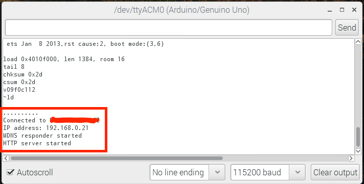
Figure 7: Serial output for web server. Notice the IP address. This is where you will navigate to find your LED button. The previous information is just routine output for the ESP module when it is interrupted to reboot and enter normal operation.
The next piece of code handles the root and page locations and what happens when pages are visited. When the command server.on("/",[](){}); is called - the web server creates a page and handles the navigation to that page. That is why we see either a function or a server.send(200,"text/plain","Page"). In the case below, we have 5 different pages that do different things. I recommend uploading the sketch and exploring the behavior of these pages and different methods.
  server.on("/", handleRoot);

  server.on("/inline", [](){
    server.send(200, "text/plain", "this works as well");
  });

  server.on("/page_3", [](){
    server.send(200, "text/plain", "Page 3");
  });

  server.on("/led_on",handle_on);
  server.on("/led_off",handle_off);

  server.onNotFound(handleNotFound);

  server.begin();
  Serial.println("HTTP server started");
Finally, the user should have enough information about the web server to upload the full sketch found here. Once the sketch is uploaded (after following the instructions above and the NOTE in red), the user should be able to navigate to their respective IP address and control an LED on pin 5 (GPIO 0) of the ESP8266. For Wiring of the LED, see below where I have created a table for wiring the LED to pin 3 or 5.
Wiring The ESP8266 After Flashing (Uploading Sketch)
The LED should be wired to either pin 3 or 5. I use pin 5 in the sketch above, so we can start there. Be sure to switch pin 5 from GND to the long end of the chosen LED. I also recommend using a 1-5K resistor on the short leg of the LED as well.
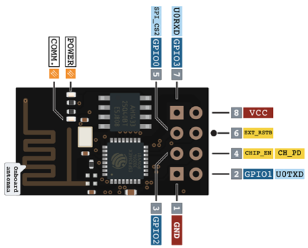
Figure 8: Wiring for Normal Function (LED Switch)
ESP8266 (Pin) | Arduino Uno (Pin)
1| GND
2| ------
3| <wire to desired effect>
4| 3.3V
5| <wire to desired effect>
6| ------ (external reset)
7| ------
8| 3.3V
Demonstration and Concluding Remarks
The screenshot to the right was taken after turning the LED on and off twice using the localhost. My particular ESP IP address was 192.168.0.21, so after typing that into any connected device's web browser (on the same WiFi network), a page similar to the one in Figure 10 should appear. This is the toggle switch that tells the ESP8266 to turn the LED on or off over WiFi. Assuming the wiring and coding is correct - this completes the ESP8266 Smart Home LED Toggle Switch tutorial! Below I demonstrate the final result in a video.
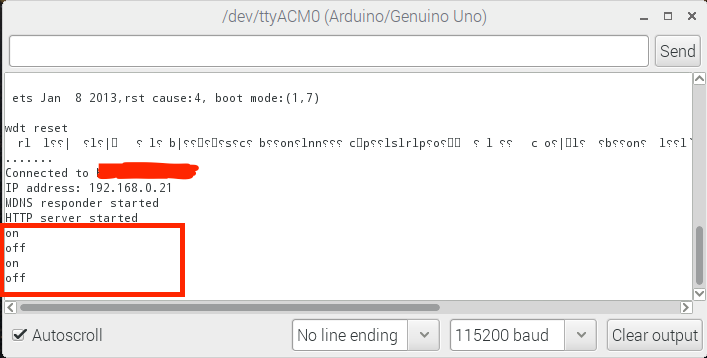
Figure 9: On and Off functionality of the web server printed on the Serial Port. The toggle switch turns the LED on and off via GPIO 0 on the ESP8266.
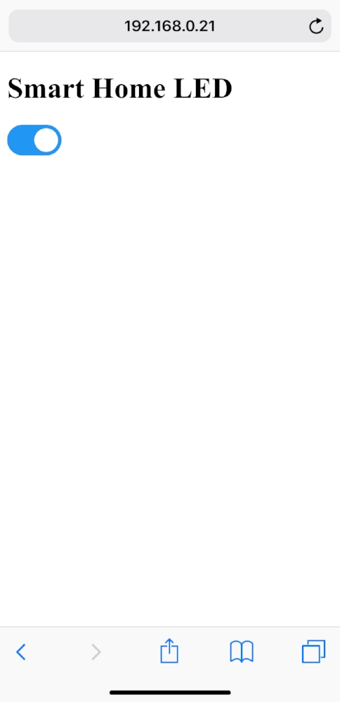
Figure 10: Screenshot of the ESP8266 web server that turns an LED on and off using a toggle button.
Concluding Remarks:
The ESP8266 MUST be powered by a source between 2.5V-3.3V, which means that the Arduino Uno is safe, but traditional LiPo batteries cannot be used to power the module unless a voltage regulator is used. I recommend the Sunkee AMS1117 3.3V Regulator.
As I said before, the server needs to be reset before uploading a new sketch, and it should also be reset after uploading a sketch but before normal operation. This can be done by either pulling pin 6 to ground, or simply turning the module off and then back on.
Programming HTML within the Arduino C++ framework is quite hard, so be sure to do some homework on string and char in the Arduino IDE before trying to create any complex HTML.
The ESP8266 allows you to host multiple pages on the domain, which allows you to create a rather intricate server. In this example, navigating to /led_on also turns the LED on. This type of web structure makes mobile app integration into the smart home easy, by taking advantage of the POST method.
The ESP8266 can be used to enable WiFi capabilities on the Arduino Uno, however, that topic was not the focus here. In this tutorial, I wanted to demonstrate how the 8-pin ESP8266 is a standalone micro controller with two GPIO pins that is capable of web service completely on its own.
There are several larger ESP8266 boards that mimic the functionality of the Arduino boards: NodeMCU, ESP-12E, Adafruit Huzzah, among others. In this tutorial, I focused on integration and affordability (as I often do). The boards above are pricey and bulky. The ESP8266 shown above is low-profile, cheap, and easy to integrate into Arduino - which is the primary reason it was chosen.
See more in IoT and Arduino: