Using Raspberry Pi, HM-10, and Bluepy To Develop An iBeacon Mesh Network (Part 1)
Bluetooth Low Energy (BLE) established a new trend of highly efficient, low cost, connected devices that had only been realizable in science fiction films. Widespread use of the Bluetooth protocol alongside low energy innovations made in wireless communication led to the exponential growth of BLE technology. BLE can transmit up to 100m, transfer data at speeds of roughly 1Mbit/s, and consumes less than 15mA at peak. The most popular BLE module for Arduino/Raspberry Pi is the HM-10, an implementation of the TI-254x module. The HM-10 has several sleep modes and intermittent transmit/receive protocols that help minimize power consumption. In this experiment, we will utilize the beacon setting on the BLE device, which emits a signal at a fixed power level and time interval. This signal is received by another BLE enabled device and approximates the distance of the beacon based on its received signal strength.
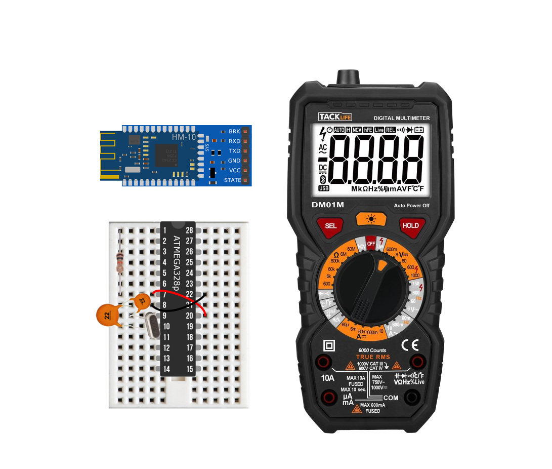
Parts List for This Experiment
Bluetooth Module - $8 (HM-10 breakout), $5 (CC2541a [HM-10 knockoff]), $4 (HM-10 unsoldered)
3.7V/600mAh LiPo Battery w/USB Charger - $15.00 [Our Store]
- Other Items -
Raspberry Pi 4 Computer - $55.00 [Our Store]
Arduino Uno Board - $13.00 [Our Store]
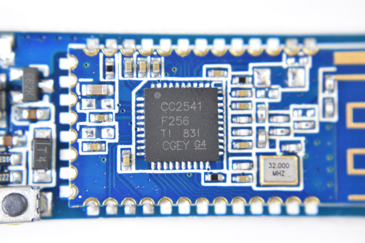
NOTE: One common mistake when buying a BLE HM-10 bluetooth module is mistaking a counterfeit board for a real one. The way to tell a counterfeit board from a real one is in the existence of the crystal in the top left section of the board. See the red circle in Figure 1: if your board does not contain this rectangular crystal, then some of the features of the HM-10 and the efficiency of its firmware may not exist. See the datasheet for the HM-10 for more.

Figure 1: HM-10 Bluetooth Module. If the board you are buying does NOT contain the rectangular crystal, then it is likely a counterfeit board and may not work properly.
Wiring and Programming the hm-10
- Wiring HM-10 To Arduino Board -
Two separate wirings are required for properly setting up the HM-10 as an iBeacon. First, the HM-10 must be programmed using an Arduino board (Uno used here). After the module is programmed as an iBeacon, it only needs a battery supply to function. Therefore, once the device is programmed, simply unplug the TX/RX pins from the HM-10 and connect the VCC/GND to 3.7V/GND leads of a battery.
The wiring for the Arduino programming portion is shown in Figure 2. Be sure to load the Bare Minimum script onto the Arduino board before hooking up the HM-10, just to prevent any unwanted behavior. Then, ensure that the HM-10 pins are properly wired to the appropriate digital pins on the Arduino. For the HM-10 I used, the RX goes to D0, and TX goes to D1. Also ensure that the VCC is to 3.3V, not 5V (unless your module states it can handle 5V). Now we will move on to the actual programming of the Bluetooth module for iBeacon support.

Figure 3: AT command set for a specific Bluetooth module (CC2541a). The full AT command set is much larger for an HM-10, but should contain all of those shown above. Full set of AT commands can be found in the datasheet here.
- Communicating With HM-10 Using AT Commands -
The HM-10 (and most CC254x boards) respond to a set of instructions called the ATtention command set, or AT commands for short (see all commands in the HM-10 datasheet here). These commands instruct the Bluetooth module to enter into several modes of operation including: low power mode, central/peripheral modes, password-protected mode, and several others. We want the iBeacon mode, which is an efficient way for the peripheral device to broadcast a signal that notifies nearby central devices of its power output. The method for finding the location is fairly imprecise, since the central device has to derive the distance by using the received signal strength. The received signal strength indicator, or RSSI, is a common method used for approximating distance between two Bluetooth devices, and is the method used here.
The AT command set uses a specific protocol for instructing the HM-10 module. First, the letters AT are used, then a + sign, then the specific command. For example, if you wanted to tell the module to print its Bluetooth address, you would type into the Arduino Serial window: 'AT+ADDR?' and the response should be 'AT+ADDR:XXXXXXXXXXXX' where the Xs are 12 unique numbers and letters that designate the Bluetooth address of the HM-10. To start, it's always a good idea to type in 'AT' to which you should receive 'OK' as a response. This tell you that the communication line is established between the Arduino and the HM-10. If you receive nothing, try switching the TX/RX wires. If there's still nothing, then try going to the bottom of the window and clicking where it says 'No line ending' and select 'Both NL & CR' - this will put a newline and carriage return at the end of each command. This function works for some CC254x modules that do not have the full HM-10 firmware installed (with the crystal).
- iBeacon Setup Using AT Commands -
At this point, your HM-10 module should have printed its Bluetooth address and any other AT response you prompted with a command. Now, you should precisely follow the instructions below to ensure your HM-10 is iBeacon enabled:
AT+RENEW
AT+RESET
AT+ADVI3
AT+NAMEiBEA0
AT+ADTY3
AT+IBEA1
AT+DELO2
AT+PWRM0
AT+RESET
The 'RENEW' command ensure that the HM-10 is not pre-programmed and renews the factory settings in the module. 'RESET' restarts the device. 'ADVI3' puts the advertising interval to roughly 318 ms (you can change this to fit your specific needs). 'NAME' creates a name that shows up when the device is scanned, here it is 'iBEA0' but it can be changed to any unique identifier. 'ADTY3' only allows advertising, this is to conserve power. 'IBEA1' officially turns on iBeacon mode. 'DELO2' puts the device into a broadcast only mode. 'PWRM0' is an auto-sleep feature. 'RESET' again resets the module ensuring all changes are set. This sequence of commands is a variation of the popular BlueLuminance tutorial found here.
NOTE: If you need to reenter the AT command mode, you need to input a VERY large string into the serial port window. The string has to be larger than 80 characters. This will wake up the module from its auto sleep mode. To return it back to sleep after wake, just type 'AT+RESET' and it will return to sleep.
Python, Bluepy, and Raspberry Pi
Now that the HM-10 is broadcasting its RSSI in iBeacon mode, we need to ensure the Raspberry Pi can read the signal. Python has a tool called Bluepy which does this quite well. You can follow the instructions on the Bluepy GitHub site (here) to download and install it onto your Pi. Please ensure your Pi has Bluetooth.
- Python Code -
The code below is a script that reads out RSSI values from different Bluetooth Low Energy devices using Bluepy. It scans every 0.35 seconds for as many BLE devices as it can find in that time frame that are broadcasting. Then, the if statement in the while loop ensure that the RSSI value being printed are from known BLE devices. You will need to find the address of your BLE device using the method shown above (AT command 'AT+ADDR?'), then the values in my code will need to be updated with those addresses. From here, the possibilities are endless: you could use the RSSI to create distance-based smart home projects, you could use the RSSI to keep track of students in a classroom, or keep track of your keys; the possibilities are endless!
#!/usr/bin/python3

import time
from bluepy.btle import Scanner, DefaultDelegate

class ScanDelegate(DefaultDelegate):
    def __init__(self):
        DefaultDelegate.__init__(self)


    def HandleDiscovery(self,dev,new_dev,new_dat):
        if new_dev:
            pass
        if new_dat:
            pass

scanner = Scanner().withDelegate(ScanDelegate())

time_diff = 0
first_time = 1
while 1:
    try:
        devices = scanner.scan(0.35)
##        print("Amount of Devices = "+str(len(devices)))
        for ii in devices:
##            print(ii.addr)
            if ii.addr == u'00:15:87:00:4e:d4' or ii.addr == u'00:15:83:10:d5:39' \
               or ii.addr == '20:ab:37:87:03:36' or ii.addr=='d4:36:39:9d:9c:5e' \
               or ii.addr== u'd4:36:39:dc:11:47':

                print("Device %s, RSSI=%d dB" % (ii.addr,ii.rssi))
                if first_time == 1:
                    first_time = 0
                    pass
                else:
                    time_diff = time.time()-time_prev


                time_prev = time.time()
                rssi_prev = ii.rssi
                continue

    except:
        continue
Conclusions
Below is a video demonstrating the implementation of this portion of the mesh network project.
For this portion of the iBeacon mesh network development I covered the aggregation and setup of the components involved in the project. The goal for part 1 was to establish the needed parts and a bit of background for configuring the Bluetooth module. At this point in the mesh network undertaking, one should be capable of establishing a connection and protocol between a Bluetooth-enabled Raspberry Pi and an HM-10. Using the python code that employs the Bluepy framework, a terminal in the Raspberry Pi should be reading out values of RSSI. From this point, you can either continue developing your own network of devices, or you can click through to part 2 of the mesh network project where I cover statistical methods for approximating real-time separation distance between transceiver and receiver (Raspberry Pi and HM-10). I will also discuss some advanced signal processing techniques that will improve the estimation of separation distance by utilizing time between received signals, standard deviation of RSSI, and Kalman filters. I hope this entry was didactic and sparked an interest in the capabilities of Bluetooth technology and the endless breadth of opportunities that the Raspberry Pi has to offer.
(Click here for Part II)
See More in IoT: