Arduino Breathing LED Functions
“As an Amazon Associates Program member, clicking on links may result in Maker Portal receiving a small commission that helps support future projects.”
A “breathing LED” is a phenomenon where an LED’s brightness smoothly changes from dark to bright and back to dark, continuing to do so and giving the illusion of an LED “breathing.” This phenomenon is similar to a lung breathing in and out. There are several ways of achieving the breathing LED phenomenon, by manual loops or mathematical functions. The trick is to create a loop that goes from peak to minimum, or using a function that does this within its bounds. In this tutorial, an Arduino board will be used in conjunction with an LED to investigate several ways of replicating the breathing LED effect, which will make creating a breathing LED a simple procedure - regardless of the application. The amount of code needed for the simplest breathing LED is as little as two lines of code, while some more complex breathing functions grow in difficulty from there.
A lot of Arduino code is single-sided, meaning that many of the loops range from zero to some number. This is because many of the functions of a microcontroller start with zero and increase positively and are related to iterables. In this section, functions are explored that have a peak at their midpoint and maintain smoothness throughout the function. These functions will create the ‘breathing’ of the LED by starting with minimal brightness, peaking in brightness, and going back to minimal brightness - all without any abrupt changes. This is similar to the intake and exhale of air into a lung. The list of five functions explored in this tutorial are given below:

Depending on the desired effect, the functions above give different variability in amount of brightness and darkness during the cycle of the LED breathing. For example, the plot below is an annotated version of the plot above, pointing to the functions that favor brightness and the functions that favor darkness:

The relationship between brightness and the duty cycle of a pulse-width modulation (analogwrite() function) is linear, and has been observed as such in the literature (see example here). Therefore, we expect the linear sweep (triangular function) to be the decider of whether darkness or lightness is favored. Using this principle, the Gaussian decidedly favors darkness in the plot above, and the circular function favors brightness. In the following section, the parts list and wiring diagram are introduced for following along with the tutorial. The rest of the forthcoming sections focus on the functions and coding them, with demonstrations for each function.
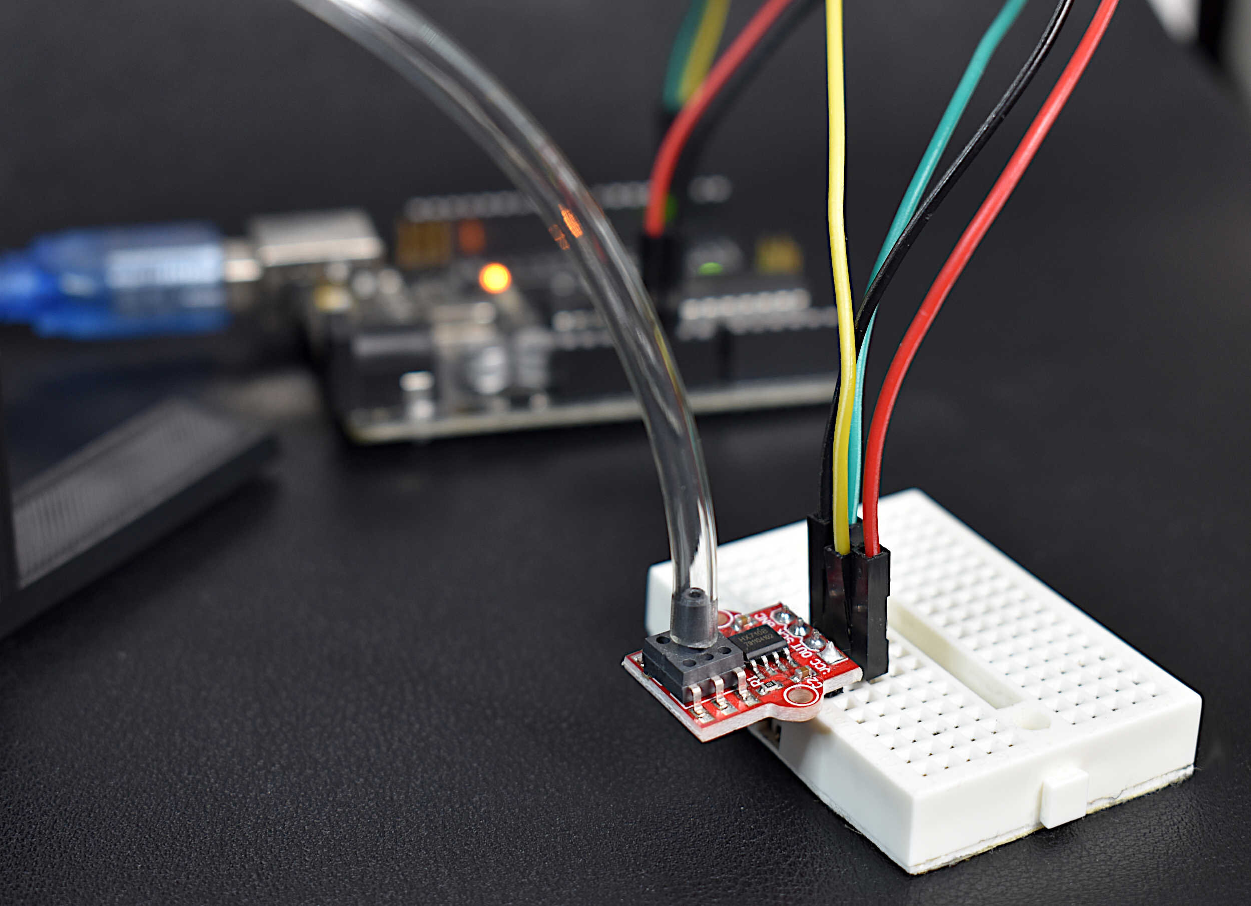
Only two parts are truly needed in this tutorial: an Arduino board and LED. A few other parts that may be useful for wiring, etc. are listed below as a guide:

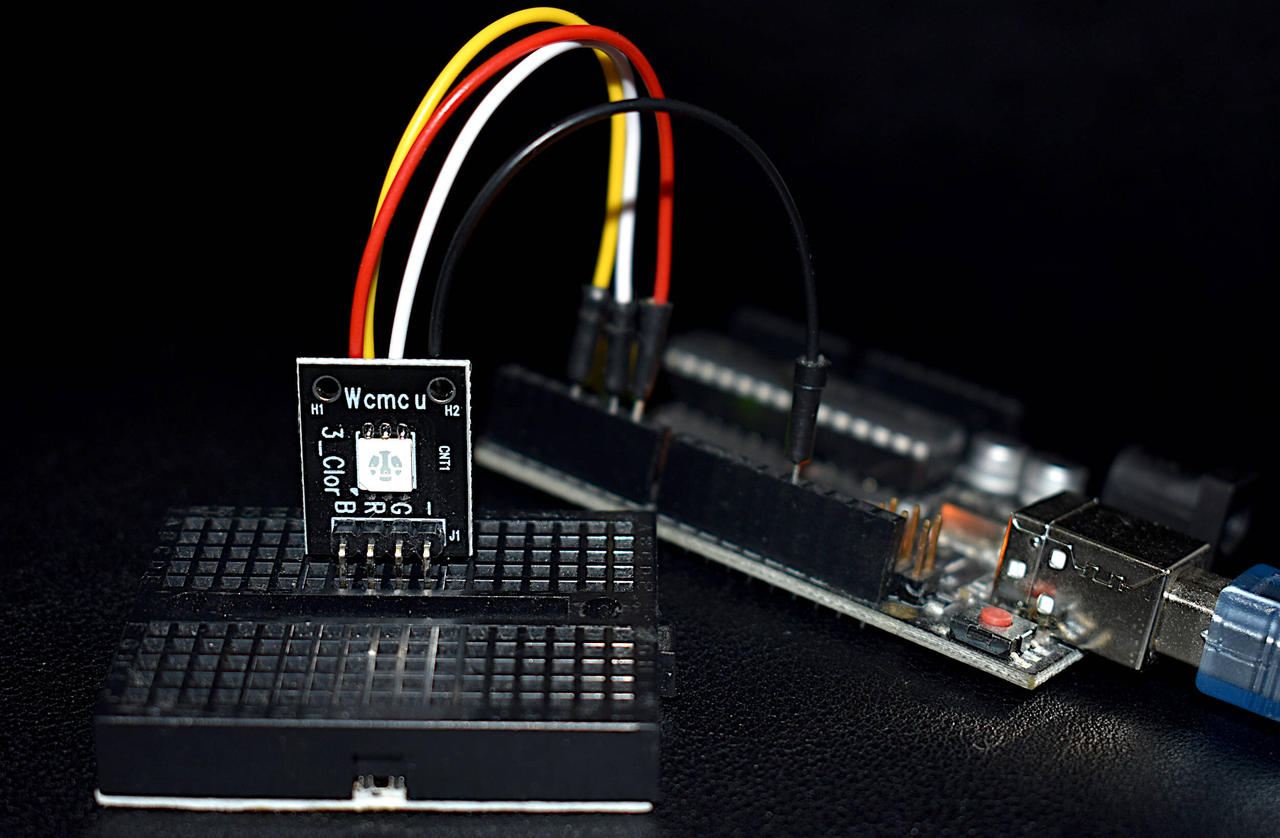
The RGB LED module allows for individual control of red, green, or blue colors all in a single module.
Included in RGB LED Module package:
1x RGB LED module
Features of RGB LED:
3.3V and 5.0V compatible
Individually addressable red, blue, and green LEDs
Arduino compatible
slim profile (4.6mm x 4.6mm RGB chip, 15mm x 24mm module dimensions)
NOTE: Our batch of these modules have reversed labels for green and red, meaning, the label R is for green, and G is for red. This was noticed after receiving and testing the modules from our manufacturer.
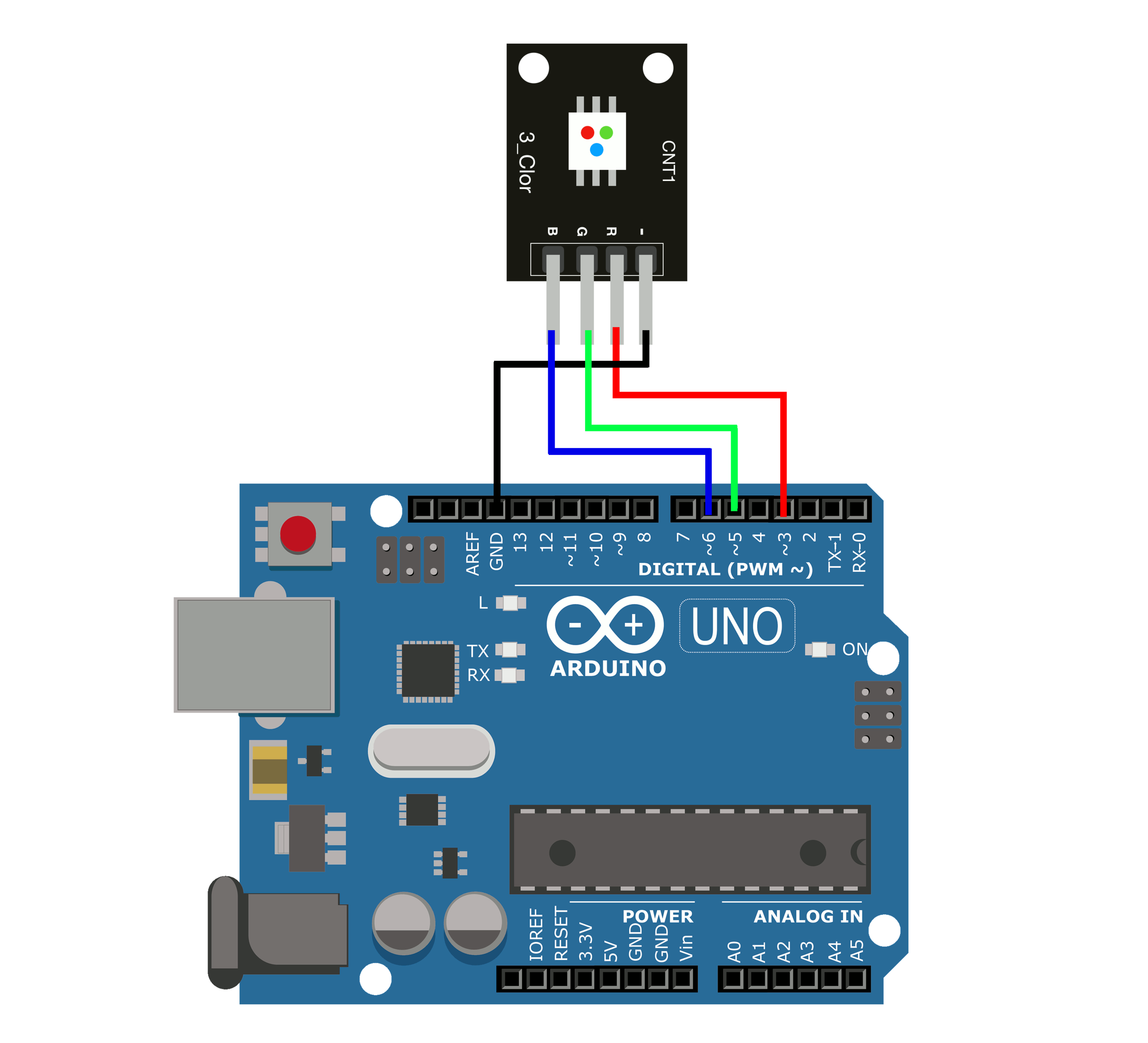
It is important to note that the LED pins have been wired to PWM-enabled Arduino pins, ensuring that the ‘breathing’ phenomenon will be possible on the chosen pins (on the Arduino Uno these pins have a ~ next to them).
The first and simplest method of creating a breathing LED is by linearly spanning from minimum to maximum through what is called a triangle wave. A triangle wave can be written in equation form as follows:
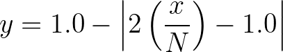
where x represents the input from 0 - N, with N acting as the total number of points in each loop. Note: y varies from 0-1, so we need to multiply the entire equation by the PWM amplitude (which, in Arduino is 255.0, or an 8-bit PWM). In Arduino, this can be coded as follows:
// RGB LED Triangle Wave Breathing LED

int led_pins[4] = {3,5,6};
int jj = 0; // 0 = red, 1 = green, 2 = blue
float smoothness_pts = 500;//larger=slower change in brightness

void setup() {
  Serial.begin(9600);
  for (int ii = 0;ii<sizeof(led_pins)/sizeof(int);ii++){
    pinMode(led_pins[ii],OUTPUT);
  }
}

void loop() {
  for (int ii=0;ii<smoothness_pts;ii++){
    float pwm_val = 255.0*(1.0 -  abs((2.0*(ii/smoothness_pts))-1.0));
    analogWrite(led_pins[jj],int(pwm_val));
    delay(5);
    Serial.println(int(pwm_val));
  }
}
Opening the serial plotter, one should see the following profile being plotted:
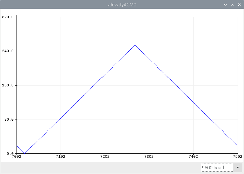
The wave spans from 0 - 255, in a uniform profile. A video of this is also given below as a demonstration of the code and triangle wave profile:
Now, a circular function will be used to favor brightness in the breathing of the LED. This function uses a circle as the basis for spanning darkness to brightness. The equation can be written as follows:

again, x represents the input from 0 - N, with N acting as the total number of points in each loop. y varies from 0-1, so we again need to multiply by the PWM amplitude (255). In Arduino, the code is as follows:
// RGB LED Circle Wave Breathing LED

int led_pins[4] = {3,5,6};
int jj = 0; // 0 = red, 1 = green, 2 = blue
float smoothness_pts = 500;//larger=slower change in brightness

void setup() {
  Serial.begin(9600);
  for (int ii = 0;ii<sizeof(led_pins)/sizeof(int);ii++){
    pinMode(led_pins[ii],OUTPUT);
  }
}

void loop() {
  for (int ii=0;ii<smoothness_pts;ii++){
    float pwm_val = 255.0*sqrt(1.0 -  pow(abs((2.0*(ii/smoothness_pts))-1.0),2.0));
    analogWrite(led_pins[jj],int(pwm_val));
    delay(5);
    Serial.println(int(pwm_val));
  }
}
Plotting on the Arduino serial plotter gives the following nice profile:

The final equation that will be investigated is the most complex, versatile, and interesting. Gaussian functions can be found in many disciplines in science, math, and engineering. The Gaussian function can be used in image processing as a smoothing tool, statistics to describe normally distributed data, and even quantum mechanics to describe quantum harmonic oscillators [read more on Gaussian functions here, here, here, and here].
The 1-D gaussian equation can be written as follows:
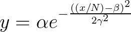
where, again x is the variable ranging from 0 - N. For the Gaussian, the constant α represents the maximum amplitude of the PWM output (255 for the Uno board). Additionally, the constant β here is 0.5, as it needs to be symmetric around x. Finally, the constant γ represents a parameter that controls the width of the wave. For the Arduino, changing γ results in either more or less darkness. Therefore, the Gaussian for our breathing LED can be written as:

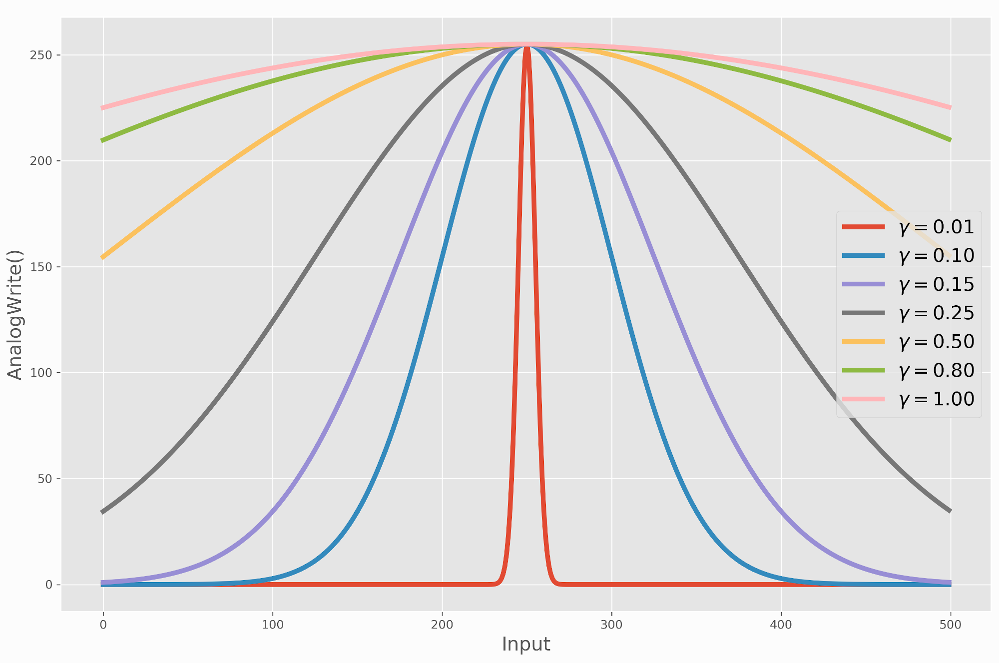
This is plotted below for various values of γ:
Varying -
γ
γ
= 0.01 is mostly dark
γ = 1.0 is mostly bright
A good range of values to ensure perceptible ‘breathing’ is 0.1 < γ < 0.3. Outside of this range the LED looks like it’s either blinking (0.1<γ) or staying on completely (γ>0.3). The Arduino code that implements the Gaussian is given below, where a value of γ = 0.14 was chosen based on its smooth profile and ability to replicate the ‘breathing’ phenomenon.
// RGB LED Gaussian Wave Breathing LED

int led_pins[4] = {3,5,6};
int jj = 1; // 0 = red, 1 = green, 2 = blue
float smoothness_pts = 500;//larger=slower change in brightness

float gamma = 0.14; // affects the width of peak (more or less darkness)
float beta = 0.5; // shifts the gaussian to be symmetric

void setup() {
  Serial.begin(9600);
  for (int ii = 0;ii<sizeof(led_pins)/sizeof(int);ii++){
    pinMode(led_pins[ii],OUTPUT);
  }
}

void loop() {
  for (int ii=0;ii<smoothness_pts;ii++){
    float pwm_val = 255.0*(exp(-(pow(((ii/smoothness_pts)-beta)/gamma,2.0))/2.0));
    analogWrite(led_pins[jj],int(pwm_val));
    delay(5);
    Serial.println(int(pwm_val));
  }
}
Using Arduino’s serial plotter shows the really smooth profile associated with the Gaussian:

The Gaussian is perhaps the most natural display of a ‘breathing’ LED, likely due to its smoothness at the darker ends. This smoothness makes it easier for our eyes to perceive the changes in brightness as delicate, rather than abrupt. The circle function is a fairly abrupt change in brightness toward the darker sections, and even the triangle wave is perceived as spending too little time on the darker sections. The Gaussian function, with γ = 0.2 gives the best ‘breathing’ phenomenon, but never goes to zero (plotting the function demonstrates why). For some reason, the LEDs do not handle tending toward off very well - so keeping them slightly on and spending more time toward darkness (with γ = 0.2, delay of 1ms, and 1000 total points per loop), the ‘breathing’ phenomenon is perceived as very natural. This is shown below:
A breathing LED is a phenomenon that mimics the inhale and exhale of a lung with light instead of air. Breathing LEDs can be found in many electronics, and are often a sign of functionality to some degree. In this tutorial, a few functions were proposed that are able to replicate the breathing phenomenon. The triangle, circular, and gaussian waves were all presented and demonstrated for an Arduino board and RGB LED. Each function uses a loop to cycle through darkness and brightness, giving the illusion of a ‘breathing’ LED. This tutorial is merely an introduction to modulating LED brightness with different mathematical functions. The goal was to create an array of methods for creating the breathing phenomenon, and this was done with the three aforementioned functions. The Gaussian wave proves to be both the most versatile and most natural of the functions, however, the simplicity of the triangle wave makes it a great (and likely common) selection for creating a breathing LED.
Follow us for more updates and project insights:
See More in Arduino and LEDs: