Arduino naturally follows the Raspberry Pi when discussing maker culture and burgeoning engineers. Often, the first projects undertaken by engineering students involve Arduino boards to some capacity. Since the mid 2000s, Arduino has been developing its hardware and software to compete with the DIY electronics boom and it has (arguably) emerged as the winner. There are several boards available depending on the scale of the project, however, none is as ubiquitous as the Arduino Uno.
Schematic of the Arduino Uno
The Arduino Uno serves as the baseline for all beginner electronics enthusiasts. It has 6 analog inputs, 14 digital inputs, 32 KB flash memory, a 16 MHz clock, and weighs less than an apple [see more here]. The Uno board is a heavyweight microprocessor and has a comprehensive and prodigious open-source library to prove it.
Arduino has its own integrated development environment (IDE) of its own aptly entitled The Arduino Software IDE. The IDE uses primarily C/C++ notation and is fairly simple to follow and understand. Between the immense open-source community and the numerous online tutorial available on the web, its no hassle to get started with the Arduino Uno and its IDE.
The hardware and breadth of available software make Arduino a foundational starting point for young engineers interested in electronics and micro-control applications. Several different boards will be explored throughout the contents of this blog, with the IDE as the central programming component for each Arduino-based project. Occasionally, the Raspberry Pi will be used in conjunction with Arduino, but not exclusively - at times there will be communication with smartphones. Lastly, it is important to note the difference between the Raspberry Pi and Arduino - the Arduino is a low-power, efficient microcontroller; whereas, the Raspberry Pi is a high-functioning mini computer. The Arduino can be thought of as the worker but needs to be programmed by the Raspberry Pi. The Arduino is trained to do a job and does it relentlessly, which is why it is reliably used as a controller for numerous projects related to: home automation, video games, data measurement and analysis , robotics, speech recognition, and countless others.
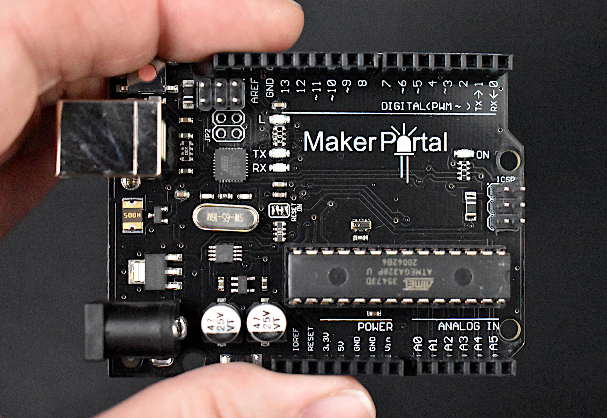
The Maker Portal Uno board is the centerpiece of many of the projects carried out in our maker spaces. The Uno board is capable of reading a wide range of sensors using analog-to-digital conversion, SPI, I2C, UART, and other common protocols. The Uno board can be used to control motors, OLED/LCD displays, and LEDs. The Arduino Uno board shown here is the official Maker Portal microcontroller, which we use in many of our projects!
Included in the Arduino Uno Package:
Maker Portal Arduino Uno Rev3 Board
Black USB Cable (1m in Length)
Specifications for Arduino Uno Rev3 Board:
ATmega328P chip with Arduino Bootloader
14 digital pins, 6 analog pins
10-bit analog-to-digital converter (ADC)
5V-12V Supply Tolerance
3.3V and 5.0V output pins
16 MHz clock
5 PWM pins, I2C support, SPI support , UART support
ATmega16U2 USB TTL, compatible with Linux, Windows, and Mac
Black Stylish Finish
Fully Integrated with Arduino IDE software
- Blog title image courtesy of oomlout under CC BY-SA 2.0
See more in Arduino:
The MakerBLE is introduced as a miniature breakout board variation of the nRF52840 Bluetooth Low Energy (BLE) Arduino board, which is capable of communicating with smartphnoes and carrying out many of the capabilities of other wirelessly-enabled microcontrollers. The MakerBLE is also compatible with our iOS app, BLExAR, and allows users to collect data, send commands, and control pins remotely from a smartphone. In this tutorial, the MakerBLE will be introduced and its capabilities will be explored from the perspective of the Arduino. This will also be the first in a series of entries geared toward low-power, BLE-enabled, tiny microcontroller projects; whether they involve remote control, data collection from sensors (I2C, SPI, UART), message transfers, BLE peripheral/central communication, or general electronics testing.
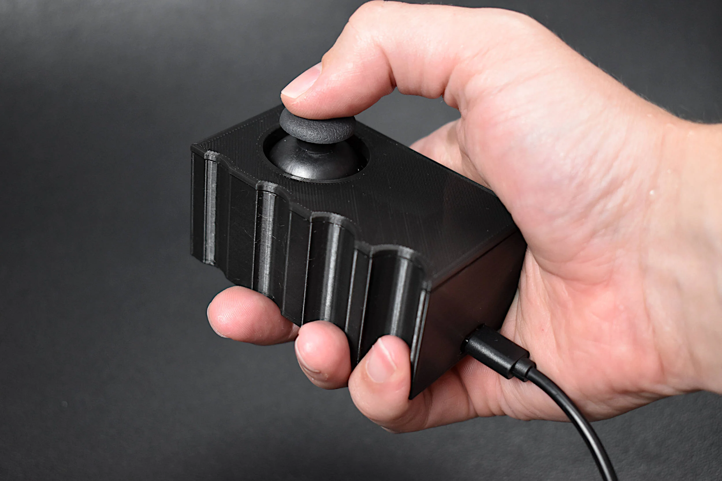
A vibration motor and joystick are used to create a haptic feedback device using the Arduino platform. As a response to specific changes in joystick position, we prescribe vibration motor actions corresponding to the movement of the joystick. This allows for creation of vibrational feedback similar to that used in video games and virtual reality systems. The goal of this tutorial is to introduce users to haptic technology that can immerse users into the digital world using physical feedback mechanisms, such as vibration. Different tunings of the vibration motor can provide users with instructions based on their input, which makes this type of application useful for enhancing digital media, as referenced above, or situations such as visually impaired navigation, feedback in auditory-restricted environments, and delivering quiet notifications to users. Haptics can be incredibly useful in emulating the real world and immersing users into scenarios that may otherwise be dangerous or difficult to experience. Vibrational haptic feedback is just one of a series of haptic mechanisms, and this tutorial was just a simple entry into a wide ranging and evolving field of human computer interaction.
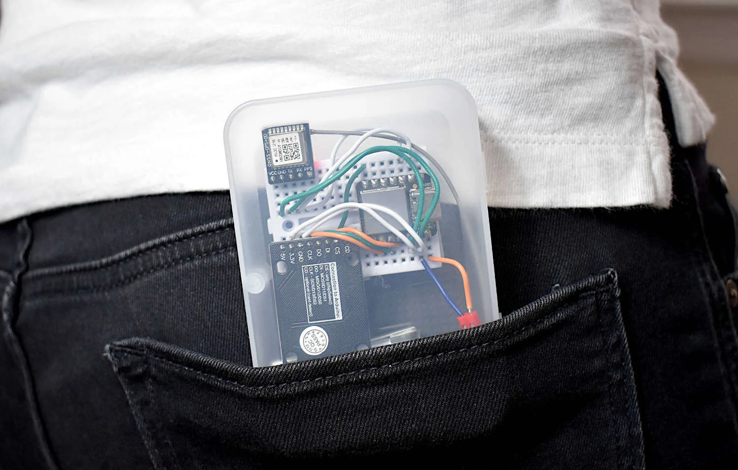
In the past, we explored the NEO-6M GPS module with Arduino through a few of our tutorials (see: "Comparing iPhone GPS Against NEO-6M with Arduino" and "Arduino GPS Tracker"). In this tutorial, we wanted to push the size limits of the portable GPS tracker by using a mini GPS module called the ATGM336H. The result is a pocket-sized GPS tracker with the low-profile by pairing the ATGM336H module with an Arduino Xiao microcontroller, SD Card Module, and 3.7V LiPo Battery. The prototype developed here will be an autonomous tracker that will record latitude/longitude at roughly 1-10 points per second (1Hz - 10Hz) and needs no external components to track geolocation. The prototype can fit in a users pocket and can track for several hours. We will also present a Python program that will plot the geolocation data points that the user can use to view the route tracked by the Arduino GPS datalogger system. The Python analysis demonstrates how well the ATGM336H GPS module and antenna are able to replicate the walking path of a human with great resolution and accuracy.
In this tutorial, a 1.54 inch e-Paper module is wired to a BLE-Nano Arduino board to communicates via SPI and display text in real time over Bluetooth. The e-Paper module here can be powered via 3.3V or 5.0V, requires very low power when refreshing (2mA-8mA), and can be completely powered off while retaining its text. An Android smartphone and the BLExAR app will be used to print text on the e-Paper display in real time, demonstrating the capabilities of electronic paper technology.
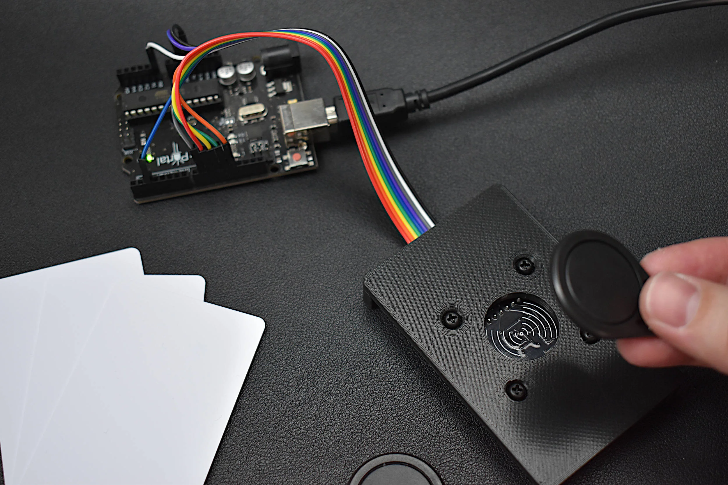
Radio Frequency Identification, or RFID, is a widely used technology developed for storing and retriving information in radio frequency-enabled devices. Most often, RFID systems consist of one or multiple RF tags, an RF reader, and a database. In this tutorial series, passive, high frequency (13.56 MHz) RFID tags are the focus, as they are very compact, inexpensive, and require no external battery power. Using an Arduino board, a common RFID reader (MFRC522), and a few RFID tags/cards, we will be exploring methods for reading and writing RFID information in an attempt to understand the how RFID communication works and the limits of the technology.
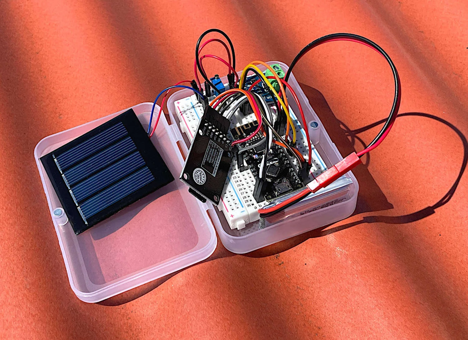
In this tutorial, the aim is to characterize a solar panel by varying the load at (near) peak solar insolation to identify the panel's nominal values such as open-circuit voltage, short-circuit current, max power voltage and current, and max power output. These values help users understand the expectations from a photovoltaic array and how their power needs may be met with a given PV system. An Arduino board will be used to log the current and voltage values outputted from a small solar panel. The current and voltage are measured using a 16-bit analog-to-digital converter power module, the INA226, which will allow us to track the power outputted from the photovoltaic panel. A potentiometer acting as a rheostat will serve as the varying load on the system, which will be used to identify the peak power points of the system. Finally, analyses will be conducted in Python 3, which will allow us to identify the peak power region and also the total power outputted over a duration of 24 hours.
The TinyBlueX is a Bluetooth Low Energy-enabled microcontroller module that combines an ATtiny85 microcontroller and CC254x Bluetooth Low Energy chip. The TinyBlueX is compatible with the Arduino platform (IDE) and the BLExAR iOS Arduino app. The TinyBlueX is very low power and has a low profile, which makes it great for very low power internet of things (IoT) applications with analog and digital sensors. The TinyBlueX can read sensors and transmit the data back to an iOS device, while also being able to read iOS commands and control LEDs, indicators, and motors. Pins 2,3,7 are available on the ATtiny85 aboard the TinyBlueX, allowing users to control/read up to 3 different devices or sensors. In this tutorial series, the TinyBlueX will be explored by instructing users on how to upload code to the module, how to control LEDs, and how to send data back to an iOS device using the BLExAR app.
Three different intermediate-level Arduino projects are introduced as a way of exploring the capabilities of the open-source microcontroller platform. First, an Arduino-based gimbal was proposed, with a video demonstration using the MPU6050 inertial measurement unit (IMU). Many commercial gimbals use similar sensors and methods for balancing objects and controlling angular and translational movement. Second, a mechanum wheels robot was presented as a way of creating a more omnidirectional robotic car, vs the normal one-dimensional movement associated with Arduino and robotic cars. Finally, an Arduino-based hovercraft was shown with motors and an Arduino at the center.
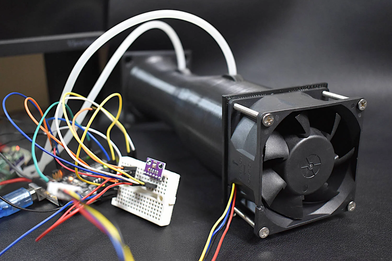
A venturi meters, sometimes referred to as venturi tube, is a flow measurement device that takes advantage of the conservation of mass and flow continuity between three separate sections within a pipe: the inlet, throat, and diffuser (outlet). Differential pressure sensors measure the pressure drop between the inlet and throat and relate it to the volumetric flow rate. The geometry of the venturi meter, along with some empirical characteristics of the flow regime, allow for very accurate quantification of flow rate. The experiment conducted here uses a 3D printed venturi meter to test an 80mm 12V DC fan across different flow rates. Pulse-width modulation (PWM) is used to control the fan's rotation speed, which creates a range of velocities through the venturi meter. The MPXV7002DP differential pressure sensor measures the pressure drop between the throat and inlet, while a BME280 measures the barometric pressure and ambient temperature.
This is the second entry into the tutorial series centered around the MakerBLE Arduino board. Using the BLExAR iOS app again, we are able to monitor the incoming data from the MakerBLE board, plot the values, and save them to a comma-separated value (CSV) file. The data being sent is read from a BMP280 sensor over the I2C port by the MakerBLE board. Temperature, atmospheric pressure, and approximate altitude were all sent over the BLE connection with an iPhone.