
BLExAR Kits:

The BLExAR Board with CC2541 Bluetooth Module is meant to interface with the BLExAR App for iOS. The BLExAR board can be controlled using the BLExAR app and an iOS device. The BLExAR board can also be programmed to communicate with an iOS device (iPhone or iPad).
The BLExAR Arduino Uno kit can be used to collect data, control robots, talk to your iOS device, and much more!
Included in the kit:
1x Arduino Uno Board
1x USB Cable
1x CC2541 Bluetooth Module
6x Male-to-Female Jumper wires

This bundle includes the necessary components to follow along with the RGB LED fade tutorial using the BLExAR app. The user will wire, program, and demonstrate how to change the color of a tri-color LED with the BLExAR app using both PWM control and on-off switches on the app. The PWM control of the RGB LED lets users select from a range of colors using a combination brightness of the three colors available on the LED.
This kit comes with the following components:
1x Maker Portal Arduino Uno Board
1x Black USB 2.0 Cable (1m)
1x CC2541 Bluetooth Module
1x RGB LED (with 3 anode legs, 1 cathode leg)
1x Mini Breadboard
8x Male-to-Male Jumper Wires
*iOS device NOT included!
NOTE: Our batch of RGB LED modules have reversed labels for green and red, meaning, the label R is for green, and G is for red. This was noticed after receiving and testing the modules from our manufacturer.

The TinyBlueX is a combination module that contains an ATtiny85 microcontroller and CC254x Bluetooth Low Energy chip that is compatible with Arduino and the BLExAR iOS app. The TinyBlueX is very low power and low profile, which makes it great for simple internet of things (IoT) applications. The TinyBlueX can read sensors and transmit the data back to an iOS device. The TinyBlueX can also be controlled using the BLExAR app to turn LEDs, motors, and actuators on and off using the ATtiny’s GPIO pins. Pins 2,3,7 are available on the module, allowing the user to control/read up to three different devices or sensors.
Included with the TinyBlueX Module:
1x TinyBlueX Module
1x ATtiny85 Microcontroller
1x CC254x Bluetooth Low Energy Module
8x Female-to-Male Jumper Wires
Features of the TinyBlueX Module:
Dimensions: 56mm x 35mm x 18mm (Assembled)
Arduino IDE Compatible (Arduino as ISP Required)
Removable ATtiny85 Microcontroller and BLE Module
3.6V - 5.5V Supply Voltage Range
Bluetooth Low Energy Communication
Compatible with BLExAR iOS App
3x Analog Input Pins (10-bit) [Pins 2,3,7]
3x General Purpose Input/Output (GPIO) Pins [Pins 2,3,7]
1x External Interrupt Pin [Pin 7]
0MHz - 10MHz @ 3.6V-5.5V, 0MHz - 20MHz @ 4.5V - 5.5V
Low Power Modes with Watchdog Timer

This Arduino Nano board is paired with a Bluetooth Low Energy (BLE) chip that makes it both an Arduino board and a BLE-enabled device. The BLE-Nano has all the functionality of an ATmega328P microcontroller (Arduino Nano) while also having an integrated BLE chip wired to its serial pins. This means that many of your Arduino projects can be Bluetooth-enabled with just a few lines of code and the BLExAR app!
NOTE: Due to supply chain issues, the BLE-Nano has been discontinued from our store. Please see the MakerBLE Arduino Board as an improvement and alternate.
Included in the BLE-Nano Package:
1x Soldered BLE Nano Board (ATmega328P + CC2540)
1x Black Micro USB Cable
Some Features of the BLE-Nano Arduino Board:
ATmega328P Microcontroller
Arduino Nano Bootloader
Operating Voltage: 5V (Input: 5V - 12V)
16 MHz Clock Speed
Available I/O Pins: 12 Digital, 8 Analog
6 Digital PWM Pins
Current Usage: 19 mA
Profile: 48 x 19mm
Weight: 7 g
Arduino IDE Compatible
CC2540 Bluetooth Low Energy Chip
Serial Communication with Nano (pins 0/1)
2.4 GHz Bluetooth Communication
Compatible with BLExAR iOS App
Onboard Antenna

The MakerBLE board is a Bluetooth Low Energy (BLE) microcontroller development board based on Nordic’s nRF52840 chip. The MakerBLE acts as an Arduino board and a BLE-enabled device. It has much of the functionality of classic Arduino boards, while also having an integrated BLE chip capable of communicating via BLE 5.0. This means that many Arduino projects can be Bluetooth-enabled with just a few lines of code and the BLExAR app!
→ Getting Started Tutorial for MakerBLE Board ←
Included in the MakerBLE Package:
1x MakerBLE Board
2x 7-Pin Header
1x Black USB-C to USB2.0 Cable (1m long)
Some Features of the MakerBLE Board:
Arduino Bootloader
Nordic nRF52840, ARM® Cortex™-M4 32-bit processor with FPU operating at 64 MHz
3.3V Operating Voltage and Logic
3.3V-5V Input voltage (3.7V LiPo Battery Compatible)
Ultra-low sleep power: 5 μA, deep sleep model
Wireless capabilities: Bluetooth 5.0, NFC, and ZigBee module with onboard antenna
Multiple Peripherals: 1x Reset button, Ix UART, 1x IIC, 1x SPI, 1x NFC, 1x SWD, 11x GPIO, 6x ADC, 1x Three-in-one LED,1x User LED
Onboard 2 MB flash
Single-sided components, surface mounting design (low profile)
14 Available I/O Pins: 11 Digital, 6 Analog
Physical Dimensions: 21mm x 17.5mm
Weight: 3 g (Unsoldered), 5g (Soldered)
Arduino IDE Compatible
GitHub Repository with example scripts and projects
Sensors:

The Raspberry Pi Pico is a microcontroller designed by the Raspberry Pi foundation. The Pico is a groundbreaking board that is meant to use MicroPython in its native micro USB port. The RP2040 is the microcontroller chip at the center of the Pico, which has a dual-core Arm Cortex M0+ processor, capable of clocking at 133 MHz, which is much faster than many of the Arduino boards currently on the market. The Pico has GPIO pins and interfaces such as: SPI, UART, I2C, PWM, and a 12-bit analog-to-digital converter (ADC). This Raspberry Pi Pico comes with the Pico microcontroller, 2x 20-pin solder header, and a micro-USB cable.
Included with the Raspberry Pi Pico Microcontroller:
1x Raspberry Pi Pico Board
2x 20-pin Headers
1x Black 0.5m Micro USB Cable
Features of the Raspberry Pi Pico:
1.8V - 5.5V Input Voltage
21 mm × 51 mm Board Geometry
RP2040 microcontroller
Dual-core Arm Cortex-M0+ processor (Clock Speed up to 133 MHz)
264KB on-chip SRAM, 2MB on-board QSPI Flash
26x GPIO pins (3x 12-bit Analog Inputs)
2x UART, 2x SPI, 2x I2C, 16x PWM
1x USB 1.1 controller and PHY, with host and device support
8x Programmable I/O (PIO) state machines for custom peripheral support
Operating temperature -20°C to +85°C
Low-power sleep and dormant modes
Onboard Temperature sensor
Accelerated integer and floating-point libraries on-chip

The MLX90640 is a 768-pixel (32 x 24), low-cost thermal camera. It uses an array of infrared detectors (and filters) to detect the radiation given off by nearby objects by taking advantage of Planck’s radiation law. The MLX90640 is most notable because of its easy-to-use Python libraries that allow it to be read by Raspberry Pi computers. The MLX90640 can be used to map and record high-resolution temperature maps at refresh rates of up to 64 times per second (64Hz).
NOTE: There are two versions here, 1. an unsoldered board that needs to be soldered to be wired properly; and 2. a version that has a breakout connector that can be connected directly to a Raspberry Pi via the JST Dupont connector.
Included in the MLX90640 Thermal Camera Sensor Package:
1x MLX90640 Thermal Camera (32 x 24 Pixels, 55° x 35°)
Pin Header
5x Male-to-Female Jumper Wires (or JST Dupont connector for breakout version)
Features of the MLX90640 Thermal Camera:
Object Detection Temperatures: -40°C to +300°C
3V-6V Supply Voltage
20mA Average Current Consumption
32 x 24 Resolution, 768 Pixels in Total
55° x 35° Field of View
I²C Communication (Address: 0x33)
Ambient Temperature Operating Range: -40°C to +85°C
Raspberry Pi and Arduino Compatible
JST Dupont Breakout Pinouts:
Black for GND
Red for V+
Blue for SDA
Yellow for SCL
MLX90640 Datasheet
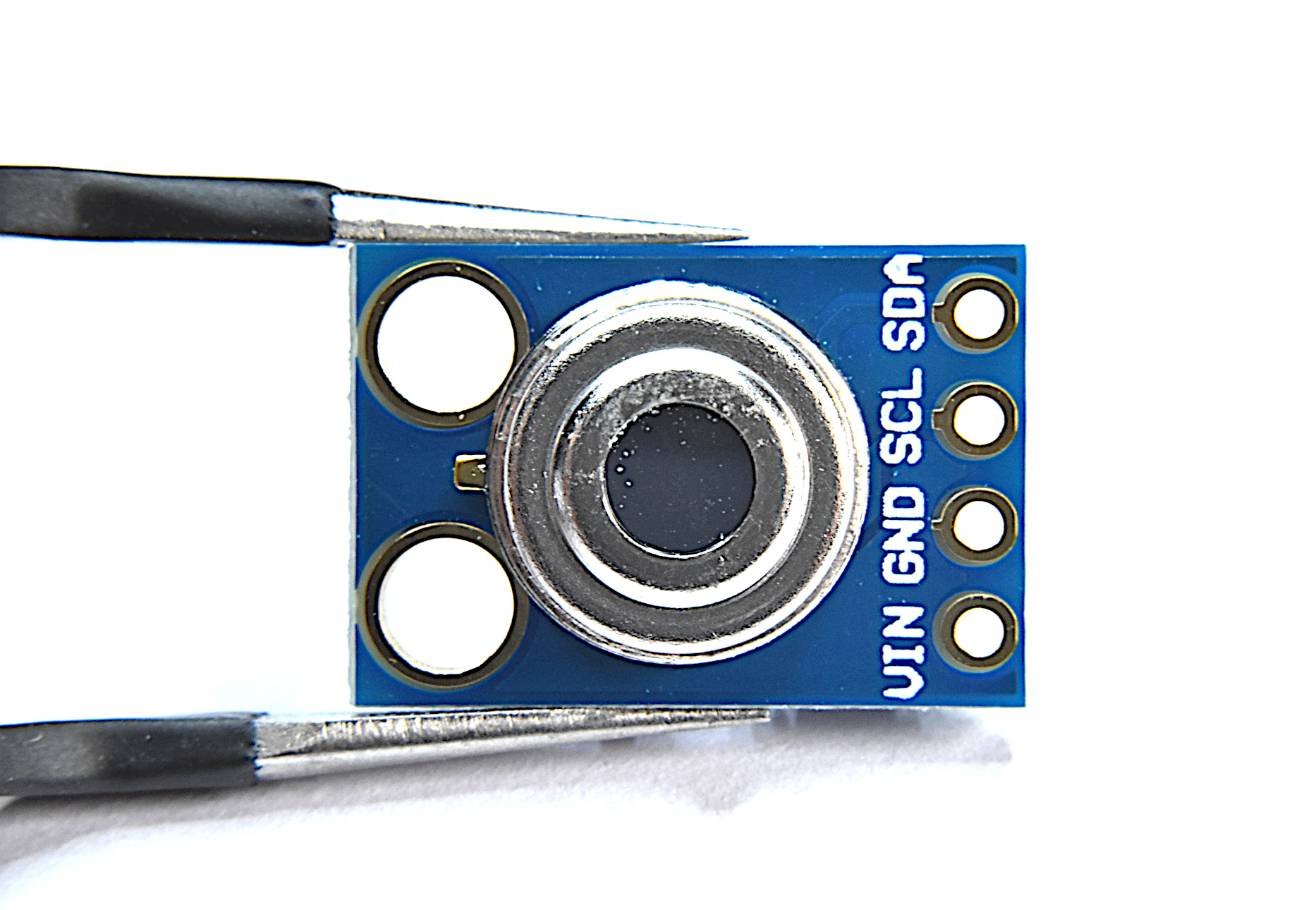
What comes in this package:
MLX90614 IR sensor
MLX90614 Specs:
3-5V Operating Voltage
-70 °C to 380 °C Object Temperature Measurement Range
0.5 °C Accuracy (0-50 °C)
0.02 °C Measurement Resolution’
At 35° Viewing Angle, Temperature is half the 0° Angle Value
I2C Wiring works with Arduino and Raspberry Pi
Full Datasheet download here

Analog joysticks can be found in video game controllers, drone and remote-controlled vehicle controllers, and heavy machinery controllers. They’re great for just about any precision control project where human interfacing is desired. The analog joystick here is one that is compatible with both Arduino and Raspberry Pi - and is a great tool for learning coding, robotic control, and functional interaction between humans and computers.
Included in the Analog Joystick Package:
1x Analog Joystick Controller
5x Female-to-Male Jumper Wires
Some Features of the Analog Joystick:
5V Input Supply
2-D Rotational + 1-D Push Analog Responses
360° Rotation in 2-D Plane
Rubber Joystick Finish for Gripping
Smooth Rotation
Clicking sound for Push Notification
Compatible with Raspberry Pi + Arduino
Code for measuring joystick rotations can be found at this tutorial:

Soil moisture can be measured using a variety of different techniques: gravimetric, nuclear, electromagnetic, tensiometric, hygrometric, among others. This sensor uses a capacitive method that exploits the dielectric properties of water in soil. Accurate measurement of soil water content is essential for applications in agronomy and botany - where the under- and over-watering of soil can result in ineffective or wasted resources.
Included in the Capacitive Soil Moisture Sensor Package:
1x Capacitive Soil Moisture Sensor
1x 3-Wire Connector
Features of the Capacitive Soil Moisture Sensor:
3.3V - 5.0V Supply Range
3.3V Operating Range
Analog Output 1.5 - 3.3V
Correlated with Volumetric Water Content 0 % - 100%
Compatible with Arduino and Raspberry Pi
Full tutorial can be found on blog here.
Engineering Kits:

Radio Frequency Identification (RFID) is a common technology used for access control in schools and offices, animal identification, and product asset tracking. The MFRC522 module is a 13.56MHz RFID reader/writer that uses SPI to communicate with devices. The MFRC522 is compatible with both Arduino and Raspberry Pi, and a large range of RFID tags and cards. The kit we have assembled comes with an MFRC522 module, 6 RFID tags (3 fobs, 3 cards), and a 3D printed fixture for holding the MFRC522 - which makes getting started with RFID for Arduino very easy.
Included in the MFRC522 RFID Kit for Arduino:
1x MFRC522 RFID Module
6x RFID Tags (3x Cards, 3x Fobs)
1x 3D Printed Fixture
4x M3 Screws and Nuts for Affixing the MFRC522 Module to the Fixture
9x Female-to-Male Jumper Wires
Some Features of the MFRC522 RFID Module:
3.3V and 5.0V Supply Voltage
13.56MHz Operating Frequency
SPI Communication (Arduino, Raspberry Pi Compatible)
Capable of Communication with MIFARE Tags
10cm Read Range (between tag and reader)
Active Area: 30mm x 30mm
Module Dimensions: 36mm x 36mm x 7.5mm (accounting for pin headers)
MFRC522 Datasheet
See our tutorial on the MFRC522 with Arduino!
Some Features of the RFID Card:
Fully Read/Write Enabled
Can change their UID, and sectors
85.5mm x 54mm
13.56MHz Frequency Coils
MIFARE 1K Tags
Some Features of the RFID Fobs:
Read Enabled
Can write data, just not UID or manufacturer sectors
32mm x 40mm
13.56MHz Frequency Coils
MIFARE 1K Tags

This kit is geared toward engineers and makers interested in learning about solar energy and how to characterize solar cells, understand nominal values in solar technology, and how to collect meaningful data. The kit comes with a solar panel, SD card and module for datalogging, a potentiometer, and LiPo battery for portability. The user just needs to add an Arduino board and breadboard and they can start logging solar data and make calculations in their local environment.
Included in the Solar Panel Datalogger Kit:
1x 2V, 120mA Solar Panel (54mm x 54mm) [Wire Colors May Vary]
1x INA226 Voltage/Current Measurement Module
1x 1kΩ Potentiometer (Rheostat in Experiments)
1x 3.7V, 600mAh LiPo Battery + USB Charger
1x SD Datalogger Module
1x 16GB SD Card
10pcs Female-to-Male + 10pcs Male-to-Male Jumper Wires
Features of the Solar Panel Datalogger Kit:
Characterize Solar Panel by Varying 1kΩ Potentiometer
600mAh Battery Allows for Roughly 1 Day+ of Datalogging (Depending on the Arduino Board and Sleep Routines)
16GB SD Card + Module Allow for Long-Term Datalogging
INA226 Reads 16-bit Voltage and Current
54mm x 54mm Solar Panel has 4 cells each 10mm x 38mm, for an Active Area of 15.2 cm-sq
See our tutorial on using the kit: Solar Panel Characterization and Experiments with Arduino

A venturi tube is a measurement device that uses the pressure differential between two sections that differ in diameter. Using Bernoulli’s principle, the velocity and flow rate can be approximated from the pressure differential measured across the two areas within the venturi tube. The venturi tube is a popular method of calculated volumetric flow rates for gases, water and oils, and other internally flowing fluids. The venturi tube given here is designed specifically for use with 80mm DC fans. The venturi tube has been used to verify fluid dynamics theory while also characterizing the relationship between duty cycle and flow rate of the fan. The fan included in this kit has been characterized to output approximately 75 cubic feet per minute (CFM). The kit also includes the XGMP3v3 differential pressure sensor (similar to the MPXV7002DP), which makes the kit a complete bundle for measuring real-world flows through a venturi tube.
See the Venturi Tube in action on Youtube.
Included in the Venturi Tube Flow Meter Kit:
1x 3D Printed Venturi Tube (236mm x 85mm x 85mm)
1x XGMP3v3 Differential Pressure Sensor (with JST-XH Connector)
1x 80mm x 38mm 12V DC Fan (+4x Screw Set)
2x Silicone Tubing (OD: 5mm, ID: 2.5mm, Length: 35cm Each)
20pcs Jumper Wires
Features of the Venturi Tube Flow Meter:
Dimensions: 236mm x 85mm x 85mm
Inlet Diameter: 76mm, Throat Diameter: 57mm
Roughness ~ 32μm
Most 80mm DC Fans Can be Affixed to Tube
Two Pressure Taps for 5mm Tubing (Inlet, Throat)
Features of the XGMP3v3 Differential Pressure Sensor:
-2.5 kPa to +2.5 kPa Measurement Range
3.3V Supply Voltage
24mA Max Power Consumption (10mW)
Analog Output Range: 0.2V - 2.7V
Measurement Accuracy: ±2.5% Full-Scale [kPa]
Temperature Compensated from 0°C - 60°C
Absolute Maximums: ±2x Pressure Max, -10°C to 85°C Operating Temperature
For Use with Non-Corrosive Gas (Air, Inert [Helium, Neon, Argon, etc.])
JST-XH Connector Makes Connection to Raspberry Pi or Arduino Simple
Features of the 12V 80mm x 38mm DC Fan:
Dimensions: 80mm x 38mm (Diameter x Thickness)
Input Voltage: 12V
Power Consumption: ~ 8.4W (12V, 0.7A)
Duty Cycle 25% - 100%
Volumetric Flow Rates: ~30CFM - 75CFM
Fairly noisy at high RPM (duty cycle 100%, 5500RPM, roughly 50dBA)

The NEMA 17 stepper motor (Model: 17HS4023) is a powerful motor capable of microstepping, high-speed rotation, and high-torque holding. The stepper motor kit also includes a DRV8825 stepper driver and motor bridge, which makes getting started with motor driving easy. With the stepper bridge, only a Raspberry Pi or Arduino, 12V supply, and five jumper wires are needed to control the NEMA 17 stepper motor. This stepper kit can be used in applications involving 3D printers, DIY CNC machines, precise camera movement, LiDAR rotation, among others!
Included in the NEMA 17 Stepper Motor Kit:
1x NEMA-17HS4023 Stepper Motor
1x DRV8825 Stepper Driver with Heat Sink
1x DRV8825 Driver Bridge
5x Female-to-Female Jumper Wires
1x Stepper-to-Bridge Connector Wire
Features of the NEMA-17HS4023 Motor:
42mm x 42mm x 23mm (LxWxH - Approximate Dimensions)
Micro-stepping down from 1.8° down to 0.05625°
Wide Voltage Supply Range: 5V - 24V
0.7A - 1.0A per phase (2-phases total)
130g Weight
13 N·cm Holding Torque
Clockwise and Counterclockwise Rotation
Rotation speeds at 1.8° Increments up to ~500RPM (12V, no load), ~1800RPM (24V, no load)
Controllable via Arduino or Raspberry Pi
Tutorial on the NEMA 17 Kit here

This kit uses known masses to calibrate a load cell using the linear response between strain gauges and weight under gravity. The HX711 is easily integrated with Arduino. Using this calibration kit, makers and engineers can build a low-weight measurement scale, a real-time measurement system for aerodynamic loads, a density measurement system using water, and so much more!
The Load Cell Calibration Kit includes:
1x 1 kg Load Cell
1x HX711 Strain Gauge 24-bit Amplifier
2x 3D Printed supports (one bottom, one top)
1x M5 Hex Screw, 1x M4 Hex Screw (for affixing the supports to the load cell)
3x rubber stoppers to prevent slipping
5x calibrated masses (20g, 10g, 5g, 2g, 1g)
An example video demonstration of the load cell can be found at:
NOTE: Because the supports are 3D printed, they may be slightly different from the ones photographed. They will function and appear exactly the same, with slight variations in minor striations or patterning.

The SSD1306 display is an organic light emitting diode (OLED) device that is great for small-scale Arduino, Raspberry Pi, and Raspberry Pi Pico projects that involve real-time data acquisition, communication, and debugging. The display allows users to visualize and print out information related to sensors and modules — specifically when creating internet of things (IoT) nodes with microcontrollers and wireless/headless technologies. The OLED display is a versatile and has a low profile that requires just two wires for communication (I2C), which makes it easy to integrate and control.
Included in the SSD1306 OLED Display Kit:
1x SSD1306 OLED Display
1x 3D Printed Display Stand
4x M2.5 Screw for Attaching Display to Stand
4x Rubber Stoppers for Stability
4x Female-to-Male Jumper Wires
Features of the SSD1306 OLED Display:
3V-5V Supply Range
2mA - 24mA Consumption Range (Blank to All Pixels Bright)
128 x 64 Pixel HD Resolution
I2C 2-Wire Protocol (I2C address: 0x3C)
White Display Colors Against Dark Backdrop
Compatible with Arduino, Raspberry Pi, and Raspberry Pi Pico
Module Dimensions: 25mm x 27mm
Active Display Dimensions: ~ 21mm x 12.5mm (0.96” Diagonal)
Arduino Tutorial with SSD1306 here
Raspberry Pi Pico Tutorial with SSD1306 here
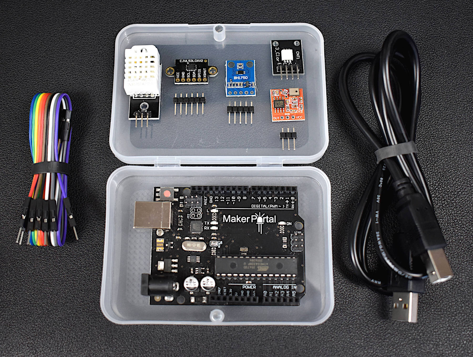
This Arduino starter kit has been tailored directly to engineers interested in real-world applications involving sensors. We avoided many of the out-of-date sensors that often accompany Arduino kits and targeted several relevant and interesting areas of engineering: temperature and humidity sensing, infrared time-of-flight distance sensing, and visible spectrum light intensity detection, and MEMS microphone audio sensing. In conjunction with these sensors, the kit also comes with an Arduino Uno microcontroller, jumper wires for connecting the sensors, an RGB LED indicator, and plastic component enclosure.
Included in the Arduino Starter Kit for Engineers (Sensor Suite):
1x Maker Portal Arduino Uno Board
1x BH1750 Light Sensor
1x DHT22 Temperature and Humidity Sensor
1x VL53L0X Time-of-Flight Distance Sensor
1x MEMS Microphone
1x RGB LED
10x Male-to-Female Jumper Wires
1x Plastic Component Box
1x USB 2.0 Cable for Arduino
Features of the Arduino Starter Kit for Engineers (Sensor Suite):
Detect light, temperature, humidity, distance, and sound
All sensors have easy-to-use Arduino-compatible libraries
The kit fits snugly into the component box, excluding the USB cable
Each sensor has a real-world application for prototyping in topics ranging from: environmental monitoring, industrial engineering, obstacle avoidance in robotics, home automation, and more!
Component Specifications:
-Specifications for the Arduino Uno Board:
ATmega328P chip with Arduino Bootloader
14 digital pins, 6 analog pins
10-bit analog-to-digital converter (ADC)
5V-12V Supply Tolerance
3.3V and 5.0V output pins
16 MHz clock
5 PWM pins, I2C support, SPI support , UART support
ATmega16U2 USB TTL, compatible with Linux, Windows, and Mac
Black Stylish Finish
Fully Integrated with Arduino IDE software
-Features of the BH1750 Light Sensor:
3.3V - 5.0V Input Voltage
16-bit ADC: 1 - 65535 lx Range
8-60Hz Sample Rate
I2C 2-Wire Communication Protocol
Supply Current - 120 µA, Power-down Current 0.01 µA
Peak Current - 7mA
400nm - 700nm Wavelength Response
-Features of the DHT22 Temperature Sensor:
3.3-6V Supply Voltage
Operating ranges:
Relative Humidity: 0-100 %
Temperature -40 °C to 80 °C
Sample Rate ~ 2 seconds
Sensitivity:
Relative Humidity: ± 0.1 %
Temperature: ± 0.1 °C
Accuracy (Drift and calibration errors):
Relative Humidity: ± 2-5 %
Temperature: ±0.5 °C
-Features of the VL53L0X ToF Sensor:
3.3V Supply Voltage
<20 mA consumption
50mm - 1.2m range (default mode), 50mm - 2.2m range (long range mode)
5 Hz - 33 Hz Sample Rate
I2C Compatible with Arduino, Raspberry Pi
Class I Infrared Laser (safe under all conditions)
-Features of the Analog MEMS Microphone:
3.0V-7.0V Supply Range
-42dBV/Pa Sensitivity
59dBA Signal-to-Noise Ratio (SNR) @ 1kHz
16mm x 15mm x 3.1mm Module Dimensions
4.72mm x 3.76mm MEMS Microphone Dimensions
100Hz - 10kHz Frequency Range (within 4dB)
3mA - 10mA Average Consumption
SPM0404HD5-PB MEMS Microphone Datasheet

Named after its french creator, Henri Pitot, a pitot tube is a device used to approximate the speed of vehicles traveling through air and other fluids. Pitot tubes, also called pitot-static tubes and Prandtl tubes, are primarily used as airspeed indicators on drones, airplanes, and other rotorcraft. Pitot tubes use basic fluid dynamics and the Bernoulli equation to approximate airspeed, or relative velocity, of a moving vehicle/flying object. The pitot tube here can be combined with our XGMP3v3 Differential Pressure Sensor to measure pressure, which is then converted to a digital signal using an Arduino board or other analog-to-digital converter (ADC). This final differential pressure can be used to derive airspeed or velocity of a moving object.
Included in the Pitot Tube Airspeed Sensor Package:
1x Metal Pitot Tube
2x Acrylic 2.5mm ID Tubing (75cm in Length)
1x XGMP3v3 Differential Pressure Sensor
1x JST-XH 3-Wire Connector (Colors May Vary)
Features of the Pitot Tube Airspeed Sensor:
3.3V Supply Voltage
0.2V - 2.7V Analog Output
Dimensions (Pitot Tube): 100mm x 16mm x 6mm
Flexible 2.5mm Tubing (75cm Length)
Aluminum Machined Metal
Selectable Pressure (Velocity) Range:
-0.5kPa to +0.5kPa -> -28m/s to +28m/s
-1.0kPa to +1.0kPa -> —41m/s to +41m/s
-2.5kPa to +2.5kPa -> -64m/s to +64m/s
Features of the XGMP3v3 Differential Pressure Sensor:
3.3V Operating Voltage
24mA Max Power Consumption (10mW)
Analog Output Range: 0.2V - 2.7V
Measurement Accuracy: ±2.5% Full-Scale [kPa]
Temperature Compensated from 0°C - 60°C
Selectable Pressure Span:
-0.5kPa to +0.5kPa (Most Sensitive)
-1.0kPa to +1.0kPa
-2.5kPa to +2.5kPa (Similar to MPXV7002DP)
Absolute Maximums: ±2x Pressure Max, -10°C to 85°C Operating Temperature
For Use with Non-Corrosive Gas (Air, Inert [Helium, Neon, Argon, etc.])
JST-XH Connector Makes Connection to Raspberry Pi or Arduino Simple
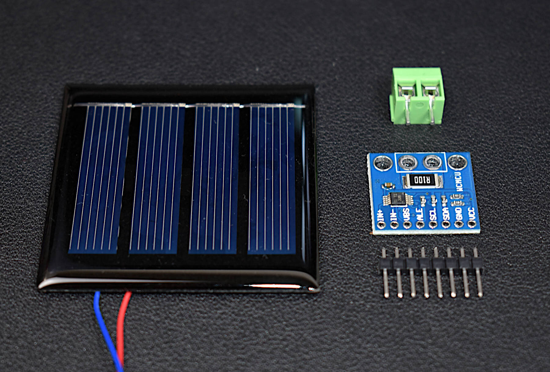
Solar panels are an essential component of the renewable energy field. The solar panels here are 2V 120mA cells that are paired with an INA226 current sensor. The goal of this kit is to allow users to test the power output from the solar panel using the current sensor and a microcontroller. Any microcontroller can be used to interface with the INA226, which gives panel voltage, current, and output power. This combination can help engineers identify the approximate predicted output from their solar panel or solar panel array to approximate efficiency of their energy harvesting, irradiance in a specific geographic region, or characterize internet of things setup requirements.
Included in the Solar Panel Power Metering Kit:
1x 200mW Solar Panel (@ 1.6V) [Wire Colors May Vary]
1x INA226 Current Sensor
1x Terminal Block
1x 8-Pin Solder Header
Features of the Solar Panel:
54mm x 54mm Dimensions
200mW Peak Power Output
2.1V Open-Circuit Voltage
123mA Short Circuit Current
1.6V Max Power Voltage
120mA Max Power Current
Epoxy Finish (Waterproof Cells, not Electronics)
Soldered Breakout Wires
Features of the INA226 Current Sensor:
Senses Bus Voltages From 0V to 36V
2.7-V to 5.5-V Input Power Supply Range
I2C Communication (Raspberry Pi, Arduino, Pico-Compatible)
High-Side or Low-Side Sensing
16-bit Analog-to-Digital Converter
Current, Voltage, and Power Outputs
Low-Power Operation (330μA Quiescent Current)
NOTE: The terminal block overlaps slightly with the shunt resistor on the INA226, however, it does not affect the functionality of the sensor.
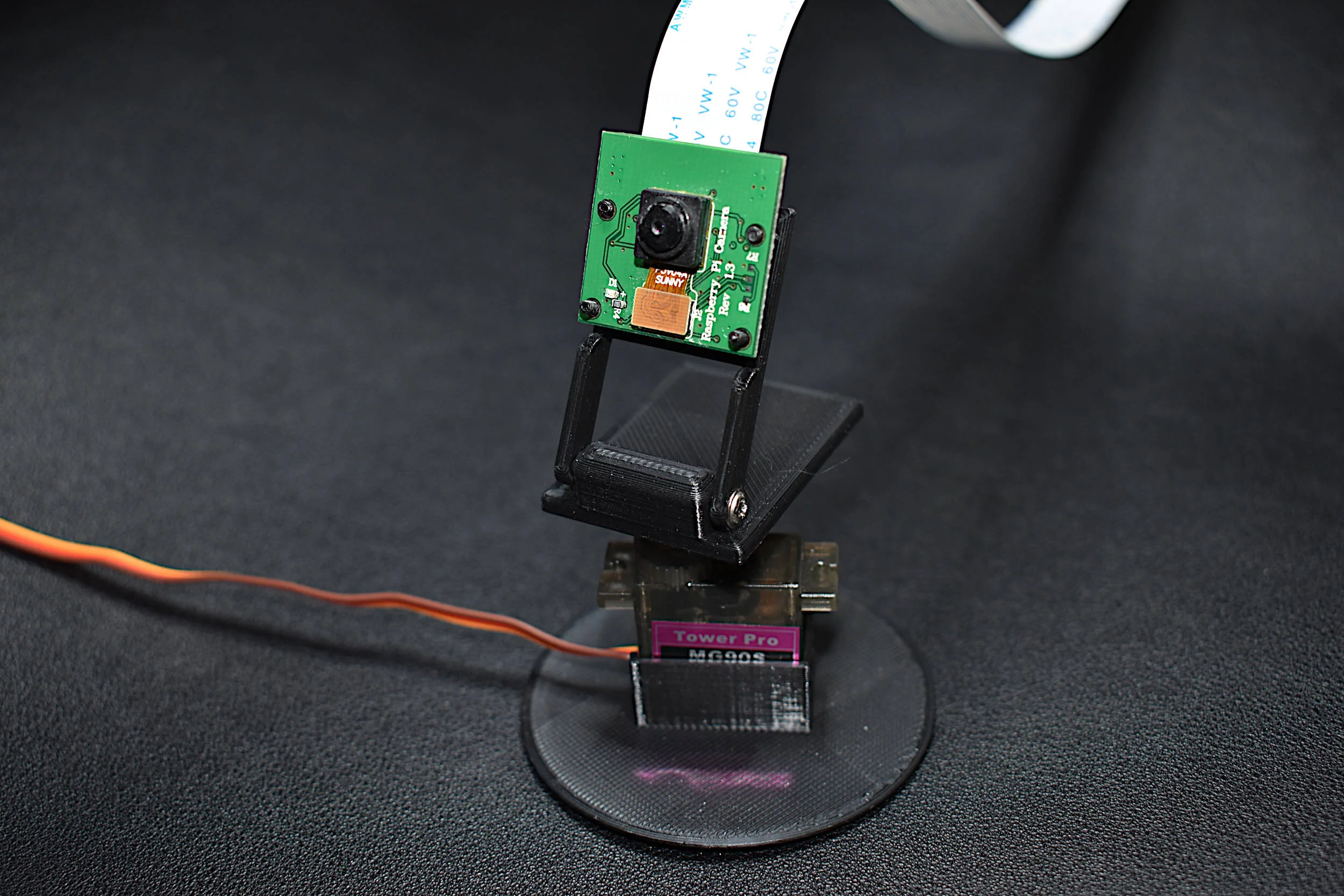
Control your PiCamera from a Raspberry Pi using a servo motor and 3D printed parts. This bundle uses an MG90S micro servo to pan the PiCamera over a 180° plane. Using Python, the user can record video captured by the Raspberry Pi and control the movement of the panning camera (we even wrote a tutorial on this: here).
Included in the PiCamera + Servo Camera Pan Bundle:
1x PiCamera V1.3
1x 50cm PiCamera Cable
1x MG90S Micro Servo
6x Pieces Servo Horns and Screws
3x Pieces 3D-Printed Servo Stand, Horn Part, and PiCamera Holder
3x Rubber Pads for Stabilization
Some Features of the PiCamera:
5MP Max photograph resolution (2592 x 1944 = 5,038,848 pixels)
Ribbon Cable that attaches directly to the Raspberry Pi
Pixel Size: 1.4 x 1.4 μm
Lens: f=3.6 mm, f/2.9
Viewing Angle: 54° x 41°
Max video resolution: 1080p @ 30fps
Max frame rate: 480p @ 90fps
Selectable video resolutions: 1080p @ 30fps, 720p @ 60fps, 480p @ 90fps
Sensor size: 3.67mm x 2.74mm (1/4" format)
Camera Module PCB dimensions: 25mm x 24mm (9mm thickness)
Some Features of the MG90S:
Input Voltage: 4.8V - 6.0V
Operating Current (5.0V): ~2.7mA (idle), ~70mA (no load), ~400mA (Stall)
Rotation Angle: 0° - 180° (Resolution: 1°)
Max Speed (5.0V): 0.6 deg/ms (full 180 degrees in 300 ms)
Largest Dimensions: 12mm x 32.5mm x 32.5mm
MG90S Datasheet
This is the DHT22 temperature sensor bundle that will provide temperature and humidity data to an Arduino which will be recorded by an iOS device via the BLExAR app. BLExAR allows users to visualize and save data in real-time.
Included in the BLExAR DHT22 Temperature Sensor Bundle:
1x Arduino Uno (w/USB Cable)
1x CC2541 Bluetooth Module
1x DHT22 Temperature Sensor
1x Mini breadboard (Colors may vary)
10x Jumper Wires
Features of the DHT22 Temperature Sensor:
3.3-6V Supply Voltage
DHT22 Operating Ranges:
Relative Humidity: 0-100 %
Temperature -40 °C to 80 °C
Sample Rate ~ 2 seconds
Sensitivity:
Relative Humidity: ± 0.1 %
Temperature: ± 0.1 °C
Accuracy (Drift and calibration errors):
Relative Humidity: ± 2-5 %
Temperature: ±0.5 °C
Specifications for Arduino Uno Rev3 Board:
ATmega328P chip with Arduino Bootloader
14 digital pins, 6 analog pins
10-bit analog-to-digital converter (ADC)
5V-12V Supply Tolerance
3.3V and 5.0V output pins
16 MHz clock
5 PWM pins, I2C support, SPI support , UART support
ATmega16U2 USB TTL, compatible with Linux, Windows, and Mac
Black Stylish Finish
Fully Integrated with Arduino IDE software
Features of the CC254x Bluetooth Module:
Active-Mode RX Down to: 17.9 mA
Active-Mode TX (0 dBm): 18.2 mA
Power Down Sleep Mode: 60uA
Wide Supply-Voltage Range (3.6 V - 5V)
Serial Communication