Thermal Camera Analysis with Raspberry Pi (AMG8833)
“As an Amazon Associates Program member, clicking on links may result in Maker Portal receiving a small commission that helps support future projects.”
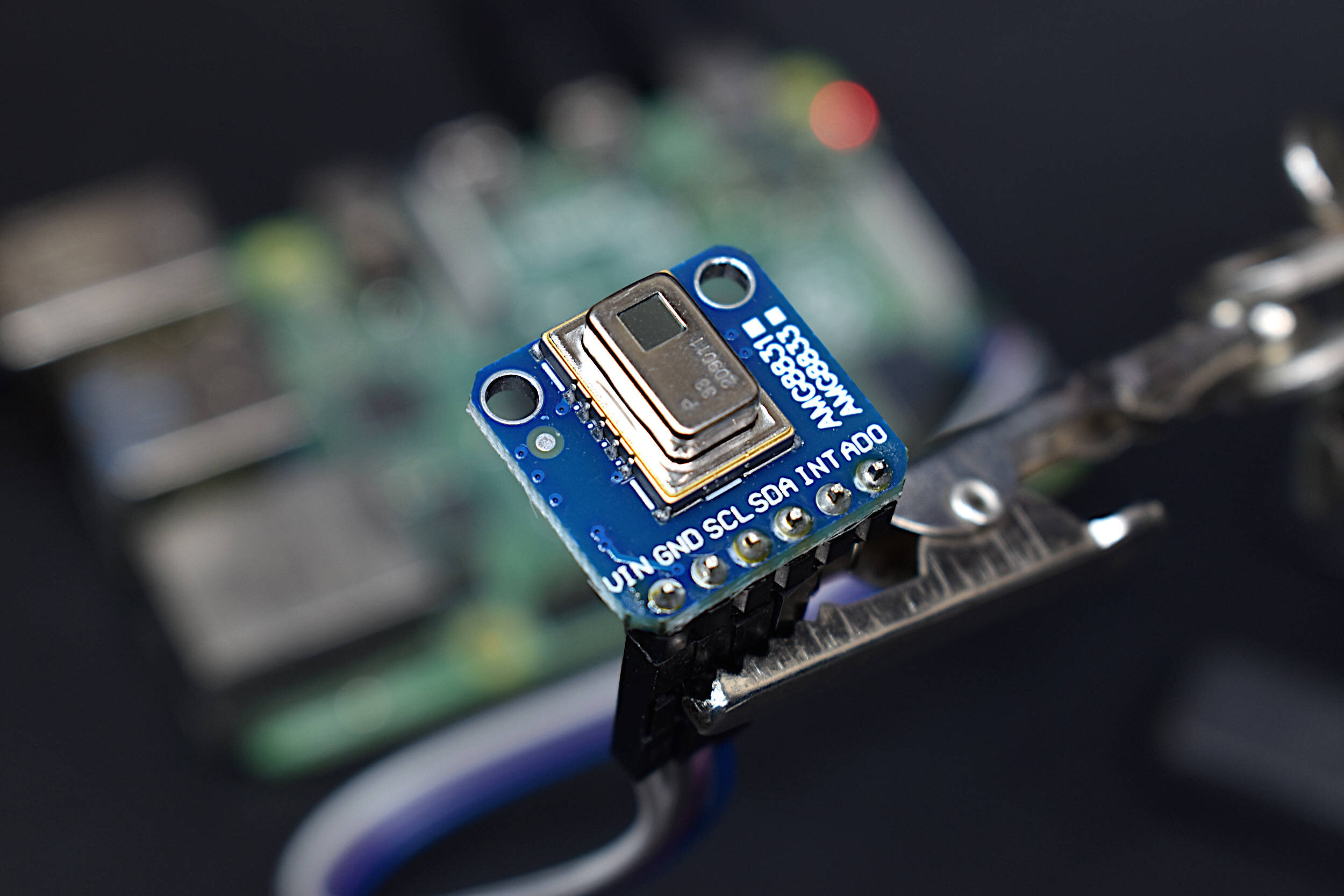
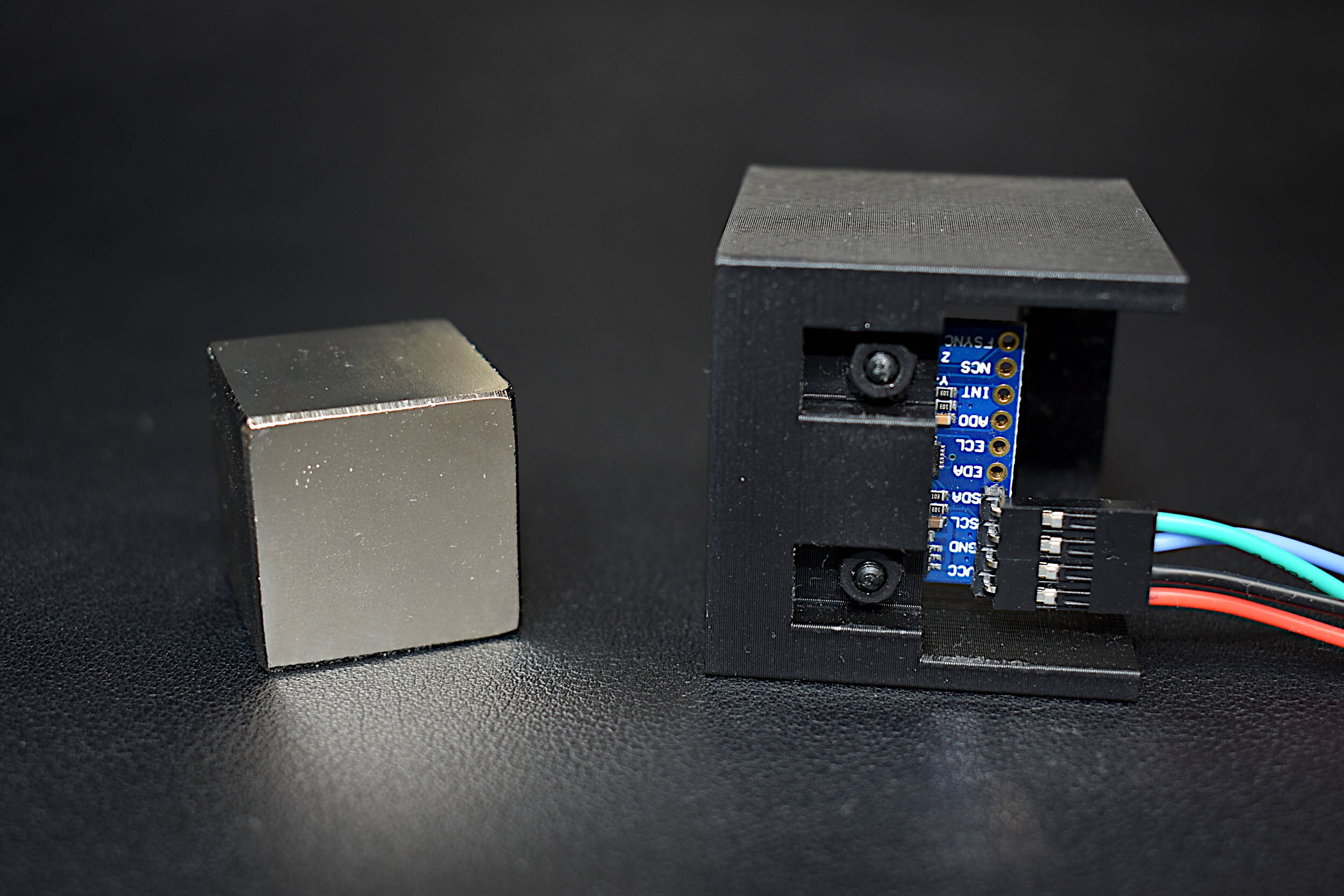
The AMG8833 is a 64-pixel temperature sensor developed by Panasonic under its Grid-EYE® product line. The sensor contains an 8x8 array of infrared thermopiles, which approximate the temperature by measuring the infrared radiation being emitted from emissive bodies. The Grid-EYE communicates via the I2C bus, which also makes it compatible with Raspberry Pi and Arduino right out of the box. The AMG8833 contains an onboard lens that limits the viewing angle of the sensor to 60-degrees, which results in a sensing region useful for objects in the mid-field (as opposed to far-field or near-field). It also operates at 3.3V and 5V, at a sample rate of 1Hz-10Hz, with an approximate temperature resolution of 0.25°C over a range of 0°C to 80°C. The AMG8833 is useful for applications in thermal imaging, heat transfer analyses, human temperature monitoring, heating and air condition management, industrial control, and other applications in non-contact temperature measurement. In this tutorial, a Raspberry Pi is used to interface with the AMG8833, with Python acting as the programming language. The wiring, testing, and analysis of the AMG8833 will be explored here, with a real-time thermal camera as the final output.
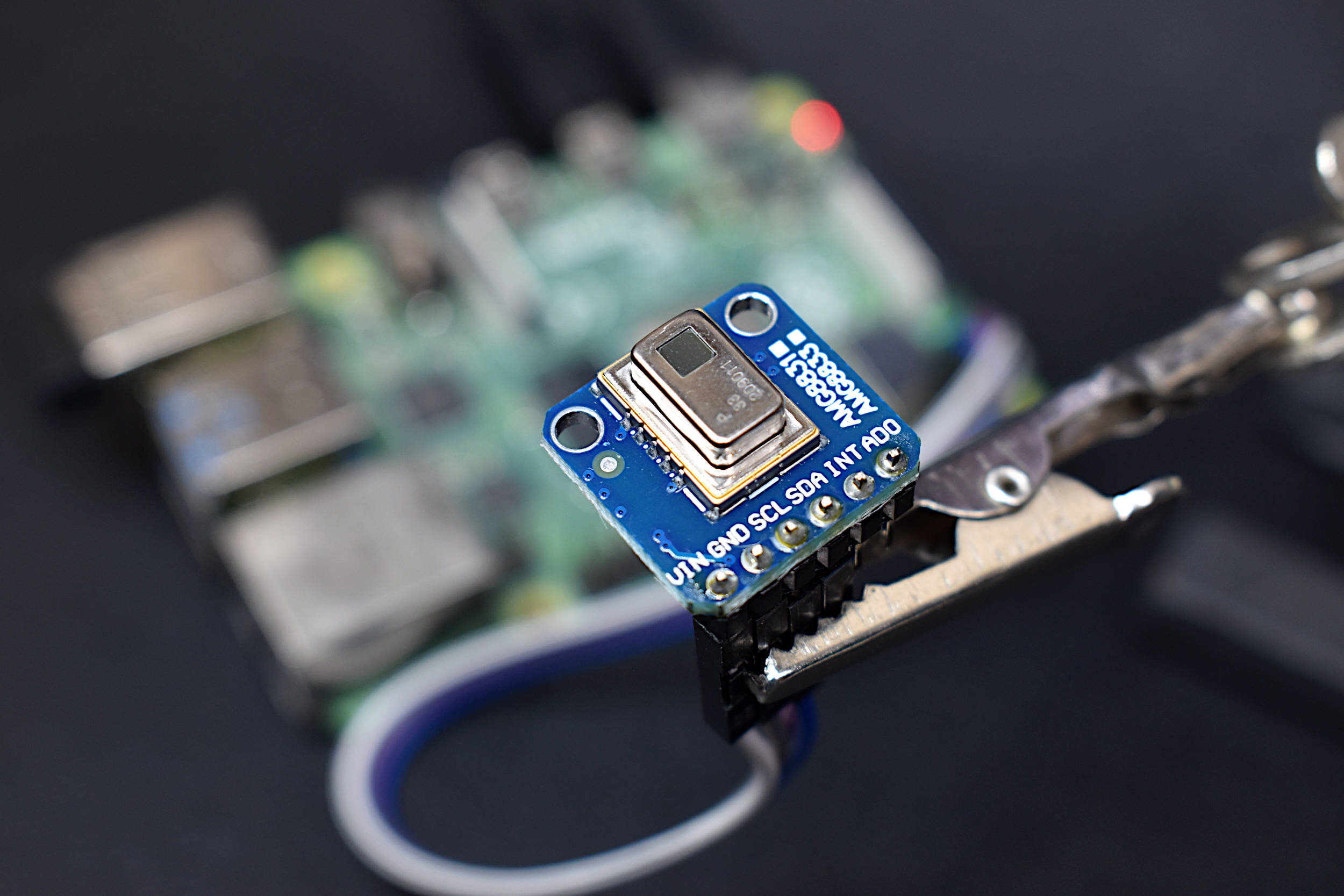
This tutorial uses the AMG8833 infrared array wired to a Raspberry Pi 4 computer communicating via the I2C bus to approximate temperatures of objects via non-contact radiation measurement. The project is quite simple in the parts list and wiring requirements, as it only requires the RPi and AMG8833 module:
AMG8833 Thermal Imager - $60.00 [Our Store]
Raspberry Pi 4 Computer - $48.99 (1GB), $49.99 (2GB), $63.41 (4GB), $88.50 (8GB) [Amazon], $55.00 [2GB from Our Store]
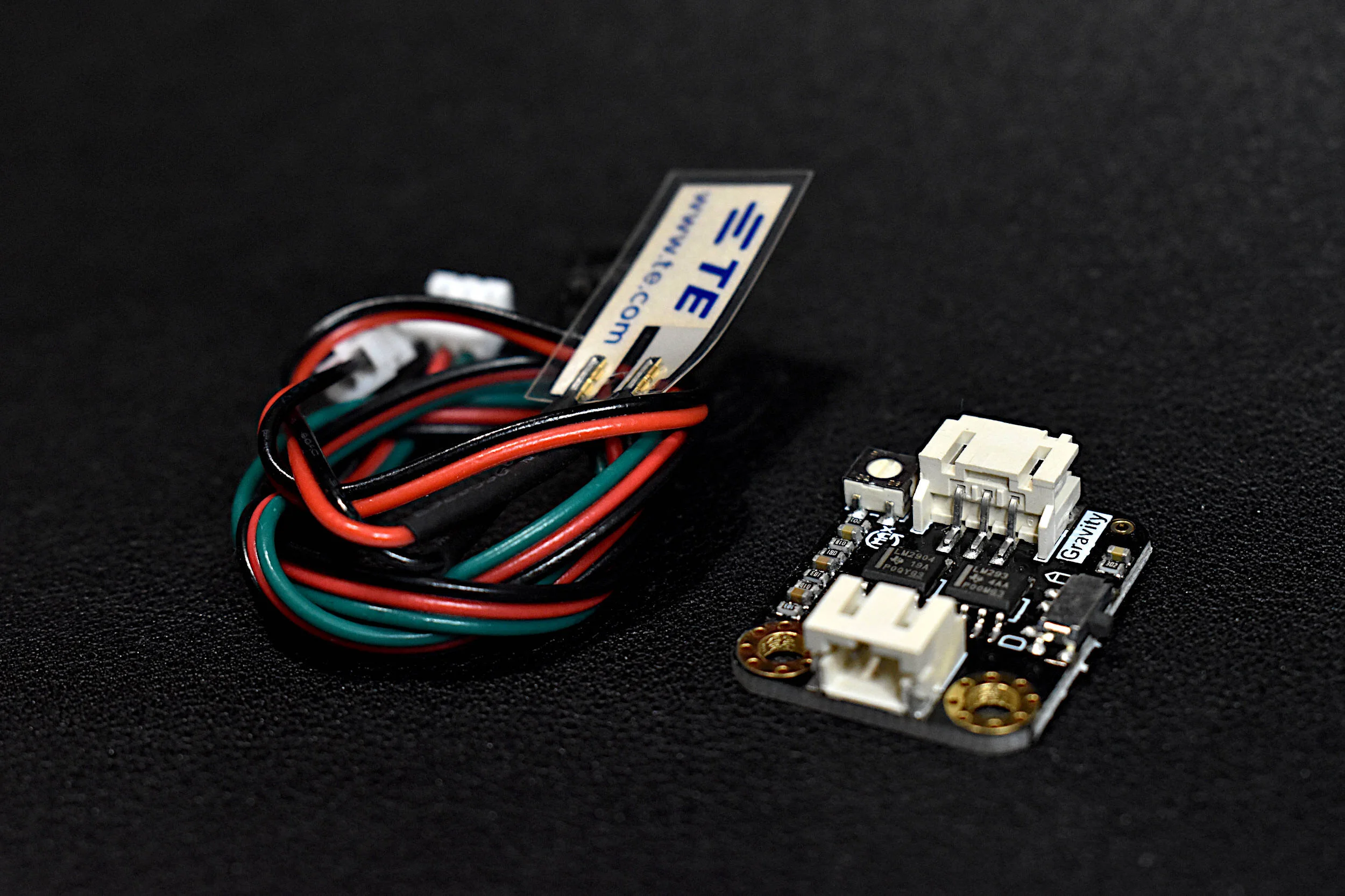
4x Female-to-Female Jumper Wires - $0.60 [Our Store]
The Raspberry Pi model technically does not matter, but we used and chose the RPi 4 Model B board for testing. The reason being - the RPi 4 has the fastest processor, which will result in faster output from the real-time visualization (more on this later). The AMG8833 from our shop has also been tested and is used for this tutorial. The assumption is that any properly wired AMG8833 module can be used to follow along in this project, however, the functionality cannot be promised.

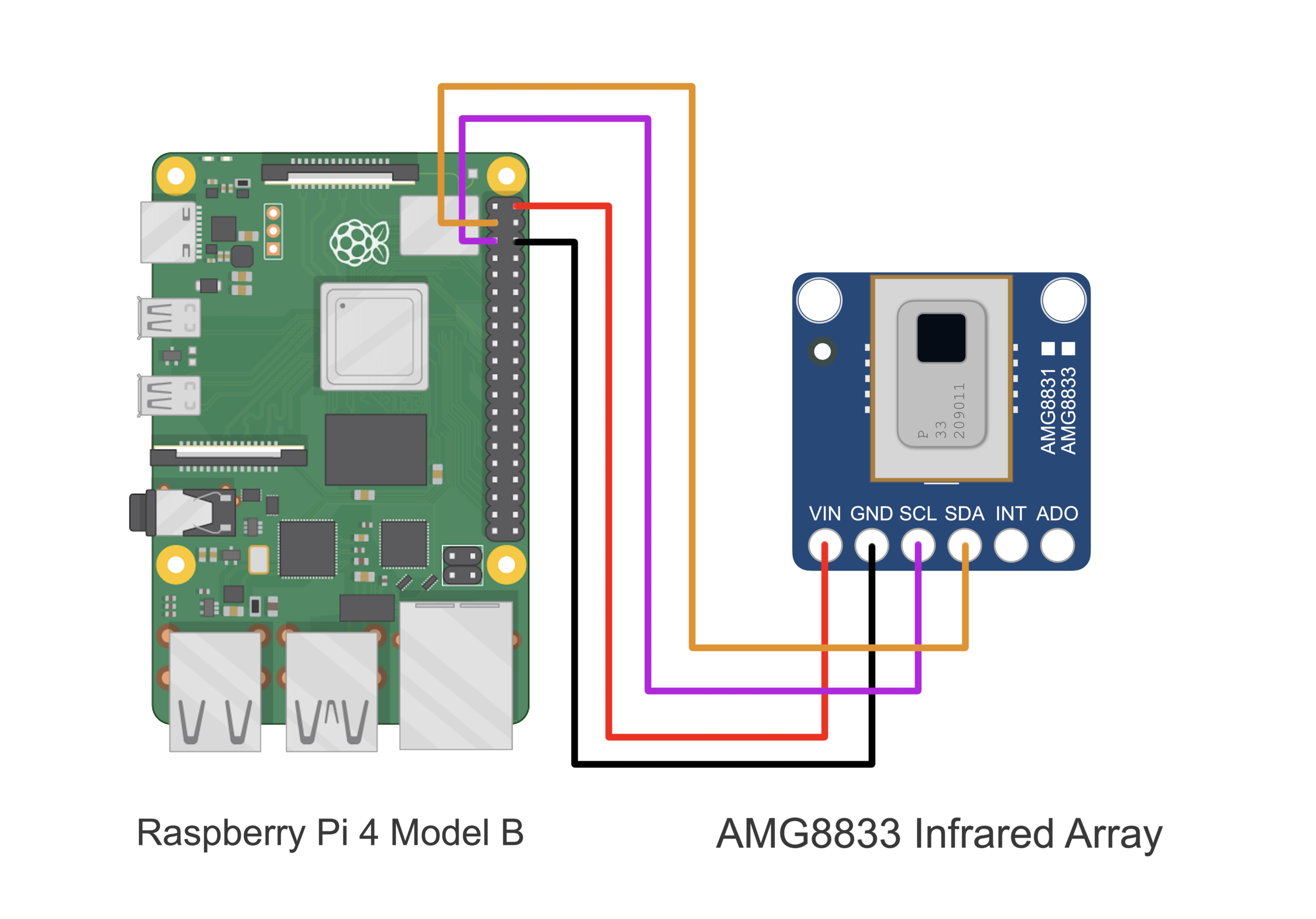
It is important to note that the AMG8833 wiring diagram below forces the I2C address of the AMG8833 to be 0x69 (this is based on the wiring of the ADO pin being raised to VIN). If the ADO pin on the AMG8833 is pulled to GND, then the I2C address moves to 0x68.
In the next section, the preparation for I2C communication on the Raspberry Pi is given.
The following set of commands enables the I2C port on the Raspberry Pi and ensures that the AMG8833 is properly wired to the RPi computer. The AMG8833 will communicate with the Raspberry Pi using the I2C protocol. In order to read and write data via I2C, we must first enable the I2C ports on the RPi. The way we do this is either using the command line or by navigating to the Preferences → Raspberry Pi Configuration. Adafruit has a great tutorial outlining this process, but an abridged version will be given below using screenshots of the RPi configuration window.
First, install smbus and I2C tools for the RPi by inputting the following into the Pi’s terminal:
pi@raspberrypi:~ $ sudo apt-get install -y python-smbus
pi@raspberrypi:~ $ sudo apt-get install -y i2c-tools
Next, enable I2C on the Raspberry Pi:

1. Preferences → Raspberry Pi Configuration

2. Select Interfaces → Enable I2C

3. Open Command Window and type “sudo i2cdetect -y 1”
Verify 0x69 as the I2C device address
NOTE: If the AD0 Pin is pulled to Ground, the I2C address will change from 0x69 to 0x68
The “i2cdetect” command ensures that the AMG8833 is at the least properly wired to the Raspberry Pi via I2C. The AMG8833 sensor communicates at 400kHz, so we will also need to ensure the Raspberry Pi I2C clock frequency is set at that rate. This can be done by opening the terminal on the RPi and typing the following to access the boot file:
pi@raspberrypi:~ $ sudo nano /boot/config.txt

Access The Raspberry Pi Boot File

Add/Change the I2C Baudrate to 400kHz
Changing the to 400kHz will ensure that the AMG8833 runs at its peak sample rate, which is configurable up to roughly 10 samples per second (10sps, 10Hz). Be sure to reboot the Raspberry Pi after enabling the I2C port and/or changing the baud rate. In the next section, the AMG8833 will be tested using the Adafruit AMG8833 Python library.
The Python library is based on the datasheet produced by Panasonic for the GRID-EYE® INFRARED ARRAY SENSOR which provides the entire breadth of information required for communicating with and configuring the AMG8833 sensor through Python. The registers and specifications are housed within that datasheet. The product sheet for the AMG88xx is a more abridged version of the datasheet and is helpful for reviewing the limits, ratings, and performance expectations of the AMG8833. The Python package developed for our analysis also uses a combination of the Adafruit and Seeed Studio packages developed for their AMG8833 boards. The major difference between our project and their projects is the implementation of our infrared camera visualization and analysis routines, which can be found on the GitHub page for this project. The AMG883 library and examples used in this tutorial can be found at the GitHub page for this project:
Once the package is downloaded to the Raspberry Pi, the AMG8833 functionality can be verified on the Raspberry Pi using one of the example scripts. The temperatures can be tested by pointing the array at different objects at different temperatures and observing the change in pixel colors (body temperature vs ambient object temperature is a good way of verifying the functionality of the sensor).
The IR camera test code example is given below, followed by the expected output image (be sure to first downloading the amg8833_i2c library before running the codes below):
#######################################################
# Thermal camera Plotter with AMG8833 Infrared Array
#
# by Joshua Hrisko
#    Copyright 2021 | Maker Portal LLC
#
#######################################################
#
import time,sys
sys.path.append('../')
# load AMG8833 module
import amg8833_i2c
import numpy as np
import matplotlib.pyplot as plt
#
#####################################
# Initialization of Sensor
#####################################
#
t0 = time.time()
sensor = []
while (time.time()-t0)<1: # wait 1sec for sensor to start
    try:
        # AD0 = GND, addr = 0x68 | AD0 = 5V, addr = 0x69
        sensor = amg8833_i2c.AMG8833(addr=0x69) # start AMG8833
    except:
        sensor = amg8833_i2c.AMG8833(addr=0x68)
    finally:
        pass
time.sleep(0.1) # wait for sensor to settle

# If no device is found, exit the script
if sensor==[]:
    print("No AMG8833 Found - Check Your Wiring")
    sys.exit(); # exit the app if AMG88xx is not found
#
#####################################
# Start and Format Figure
#####################################
#
plt.rcParams.update({'font.size':16})
fig_dims = (12,9) # figure size
fig,ax = plt.subplots(figsize=fig_dims) # start figure
pix_res = (8,8) # pixel resolution
zz = np.zeros(pix_res) # set array with zeros first
im1 = ax.imshow(zz,vmin=15,vmax=40) # plot image, with temperature bounds
cbar = fig.colorbar(im1,fraction=0.0475,pad=0.03) # colorbar
cbar.set_label('Temperature [C]',labelpad=10) # temp. label
fig.canvas.draw() # draw figure

ax_bgnd = fig.canvas.copy_from_bbox(ax.bbox) # background for speeding up runs
fig.show() # show figure
#
#####################################
# Plot AMG8833 temps in real-time
#####################################
#
pix_to_read = 64 # read all 64 pixels
while True:
    status,pixels = sensor.read_temp(pix_to_read) # read pixels with status
    if status: # if error in pixel, re-enter loop and try again
        continue

    T_thermistor = sensor.read_thermistor() # read thermistor temp
    fig.canvas.restore_region(ax_bgnd) # restore background (speeds up run)
    im1.set_data(np.reshape(pixels,pix_res)) # update plot with new temps
    ax.draw_artist(im1) # draw image again
    fig.canvas.blit(ax.bbox) # blitting - for speeding up run
    fig.canvas.flush_events() # for real-time plot
    print("Thermistor Temperature: {0:2.2f}".format(T_thermistor)) # print thermistor temp

Example AMG8833 IR Camera Output
A rough outline of a person can be seen
The example outputs the raw 8x8 pixel temperature output from the AMG8833. One thing to note is the orientation of the sensor. If the sensor image is flipped, the following command: origin='lower' can be added to move the origin to the bottom of the image, ensuring the desired orientation of the sensor image.
Now that the AMG8833 has been deemed functional using the Python test code above, simple analyses can be conducted on the infrared image output from the thermopile array. First, an interpolation routine can be added to smooth the infrared image. In this simplified case, bicubic interpolation is used to smooth the image. The code for the real-time interpolation routine is given below:
#######################################################
# Thermal camera Plotter with AMG8833 Infrared Array
# --- with interpolation routines for smoothing image
#
# by Joshua Hrisko
#    Copyright 2021 | Maker Portal LLC
#
#######################################################
#
import time,sys
sys.path.append('../')
# load AMG8833 module
import amg8833_i2c
import numpy as np
import matplotlib.pyplot as plt
from scipy import interpolate
#
#####################################
# Initialization of Sensor
#####################################
#
t0 = time.time()
sensor = []
while (time.time()-t0)<1: # wait 1sec for sensor to start
    try:
        # AD0 = GND, addr = 0x68 | AD0 = 5V, addr = 0x69
        sensor = amg8833_i2c.AMG8833(addr=0x69) # start AMG8833
    except:
        sensor = amg8833_i2c.AMG8833(addr=0x68)
    finally:
        pass
time.sleep(0.1) # wait for sensor to settle

# If no device is found, exit the script
if sensor==[]:
    print("No AMG8833 Found - Check Your Wiring")
    sys.exit(); # exit the app if AMG88xx is not found
#
#####################################
# Interpolation Properties
#####################################
#
# original resolution
pix_res = (8,8) # pixel resolution
xx,yy = (np.linspace(0,pix_res[0],pix_res[0]),
                    np.linspace(0,pix_res[1],pix_res[1]))
zz = np.zeros(pix_res) # set array with zeros first
# new resolution
pix_mult = 6 # multiplier for interpolation
interp_res = (int(pix_mult*pix_res[0]),int(pix_mult*pix_res[1]))
grid_x,grid_y = (np.linspace(0,pix_res[0],interp_res[0]),
                            np.linspace(0,pix_res[1],interp_res[1]))
# interp function
def interp(z_var):
    # cubic interpolation on the image
    # at a resolution of (pix_mult*8 x pix_mult*8)
    f = interpolate.interp2d(xx,yy,z_var,kind='cubic')
    return f(grid_x,grid_y)
grid_z = interp(zz) # interpolated image
#
#####################################
# Start and Format Figure
#####################################
#
plt.rcParams.update({'font.size':16})
fig_dims = (10,9) # figure size
fig,ax = plt.subplots(figsize=fig_dims) # start figure
fig.canvas.set_window_title('AMG8833 Image Interpolation')
im1 = ax.imshow(grid_z,vmin=18,vmax=37,cmap=plt.cm.RdBu_r) # plot image, with temperature bounds
cbar = fig.colorbar(im1,fraction=0.0475,pad=0.03) # colorbar
cbar.set_label('Temperature [C]',labelpad=10) # temp. label
fig.canvas.draw() # draw figure

ax_bgnd = fig.canvas.copy_from_bbox(ax.bbox) # background for speeding up runs
fig.show() # show figure
#
#####################################
# Plot AMG8833 temps in real-time
#####################################
#
pix_to_read = 64 # read all 64 pixels
while True:
    status,pixels = sensor.read_temp(pix_to_read) # read pixels with status
    if status: # if error in pixel, re-enter loop and try again
        continue

    T_thermistor = sensor.read_thermistor() # read thermistor temp
    fig.canvas.restore_region(ax_bgnd) # restore background (speeds up run)
    new_z = interp(np.reshape(pixels,pix_res)) # interpolated image
    im1.set_data(new_z) # update plot with new interpolated temps
    ax.draw_artist(im1) # draw image again
    fig.canvas.blit(ax.bbox) # blitting - for speeding up run
    fig.canvas.flush_events() # for real-time plot
The resulting real-time, bicubic-interpolated, infrared camera temperature output should be outputted onto the Raspberry Pi in a figure similar to the video shown below:

The output rate of the visualization above depends on the size of the figure. For the approximate (10,9) inch output with 6x interpolation, the visualization outputted at a rate of roughly 2.6 samples per second (2.6Hz). A modified resolution of (7,6) results in a sample rate of approximately 5.5Hz. At the fairly small resolution of (5,5) and 6x interpolation, the specified maximum sample rate of the AMG8833 (10Hz) was achieved. The interpolation value also affects the sample rate output. Therefore, depending on the application (high speed, higher interpolation, higher accuracy), the figure size, interpolation (image size), and sampling rate setting will all affect the output rate of the visualization.
The AMG8833 infrared thermopile array is a 64-pixel (8x8) detector that approximates temperature from radiative bodies. The module is wired to a Raspberry Pi 4 computer and communicates over the I2C bus at 400kHz to send temperature from all 64 pixels at a selectable rate of 1-10 samples per second. The temperature approximation is outputted at a resolution of 0.25°C over a range of 0°C to 80°C. A real-time infrared camera (IR camera) was introduced as a way of monitoring temperature for applications in person counting, heat transfer of electronics, indoor comfort monitoring, industrial non-contact temperature measurement, and other applications where multi-point temperature monitoring may be useful. The approximate error of the sensor over its operable range is 2.5°C, making is particularly useful for applications with larger temperature fluctuations. This tutorial is meant as the first in a series of heat transfer analyses in electronics thermal management using the AMG8833. In the next entry, the emissivity of different material types will be explored, along with validation of temperature measurements using another temperature measurement device (thermistor, thermocouple, or RTD).

See More in Sensors and Raspberry Pi