TinyBlueX - A Low Power Bluetooth Arduino Board
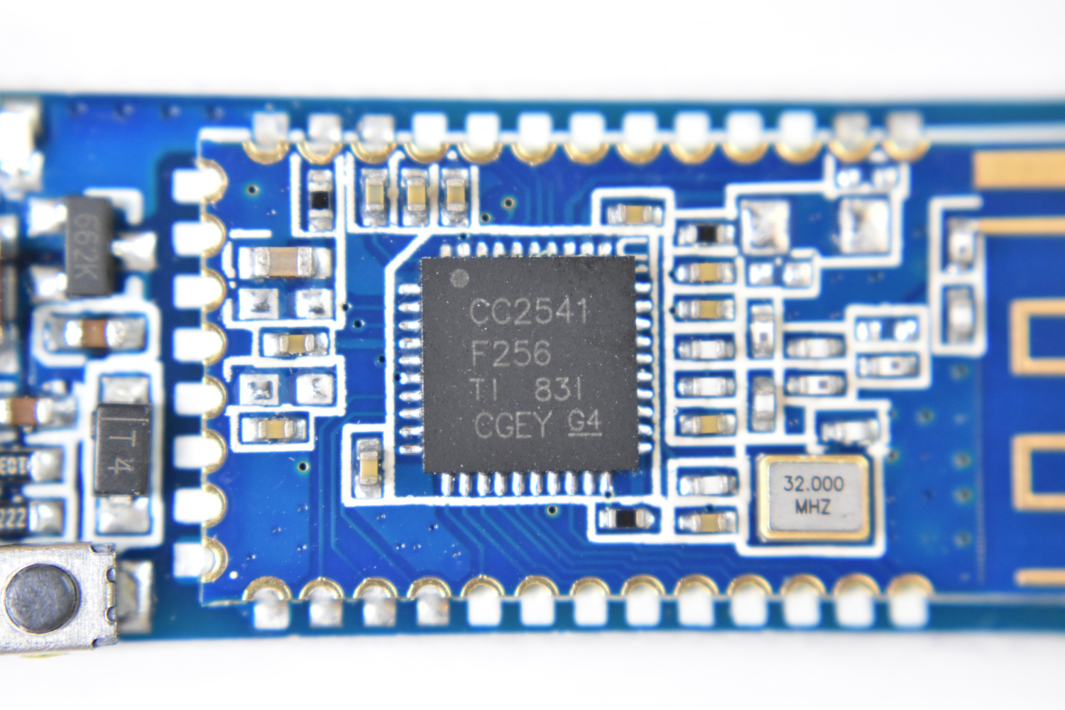
The TinyBlueX is a Bluetooth Low Energy-enabled microcontroller module that combines an ATtiny85 microcontroller and CC254x Bluetooth Low Energy chip. The TinyBlueX is compatible with the Arduino platform (IDE) and the BLExAR iOS Arduino app . The TinyBlueX is very low power and has a low profile, which makes it great for very low power internet of things (IoT) applications with analog and digital sensors. The TinyBlueX can read sensors and transmit the data back to an iOS device, while also being able to read iOS commands and control LEDs, indicators, and motors. Pins 2,3,7 are available on the ATtiny85 aboard the TinyBlueX, allowing users to control/read up to 3 different devices or sensors. In this tutorial series, the TinyBlueX will be explored by instructing users on how to upload code to the module, how to control LEDs, and how to send data back to an iOS device using the BLExAR app.
The TinyBlueX is the main component used in this tutorial, however, several sensors and indicators will be required for testing the functionality of the module. Additionally, one must use a programmer to upload code to the TinyBlueX, which can be done using an Arduino board or USB to In-system programming (ISP) adapter. We will be using an Arduino Uno board to program the TinyBlueX here. Below is the full parts list for the tutorial:
TinyBlueX Microcontroller Module - $14.00 [Our Store]
Arduino Uno Board - $13.00 [Our Store]
10μF Capacitor - $5.25 (10pcs) [Amazon]
BLExAR iOS App - $3.99 [Apple App Store]

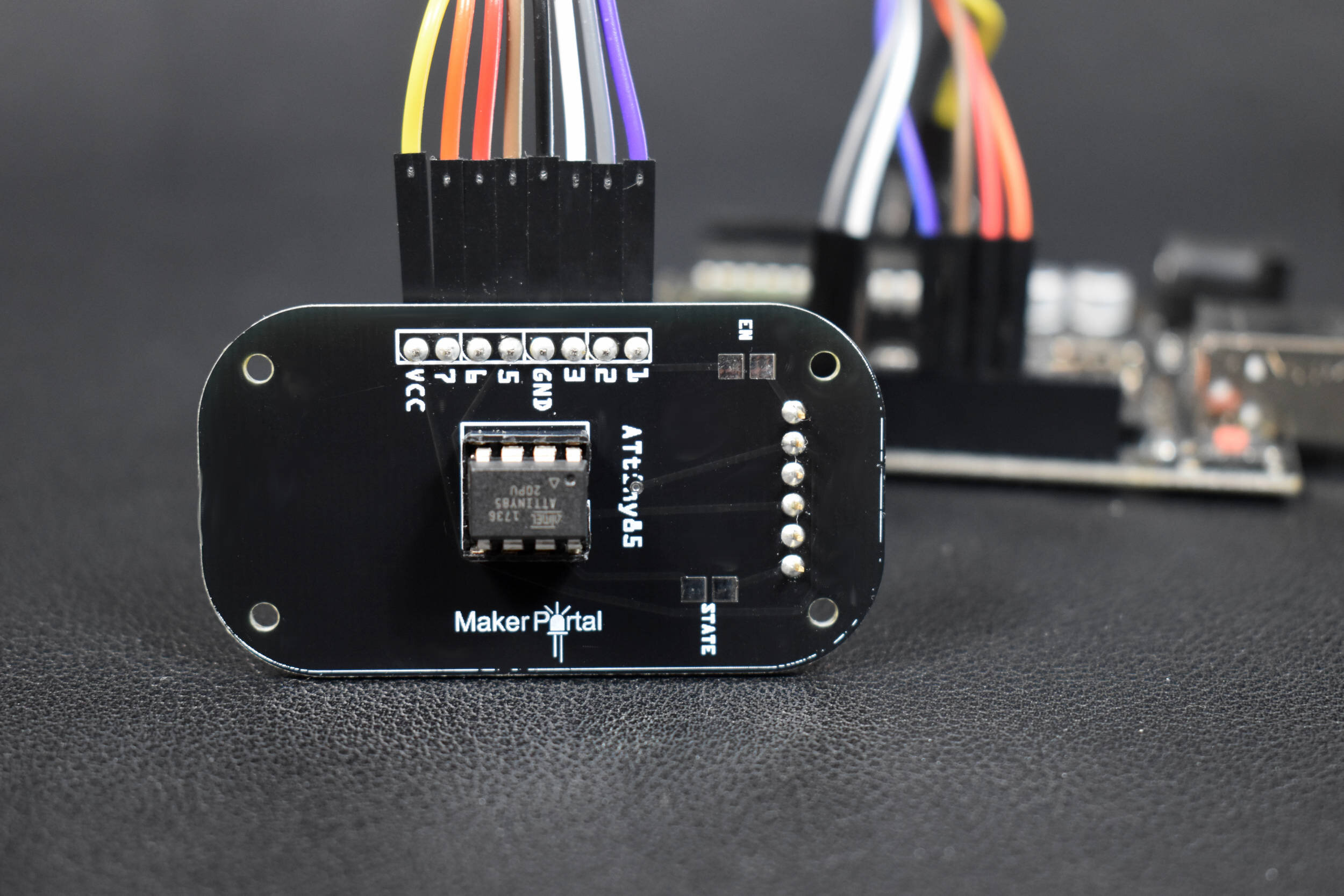
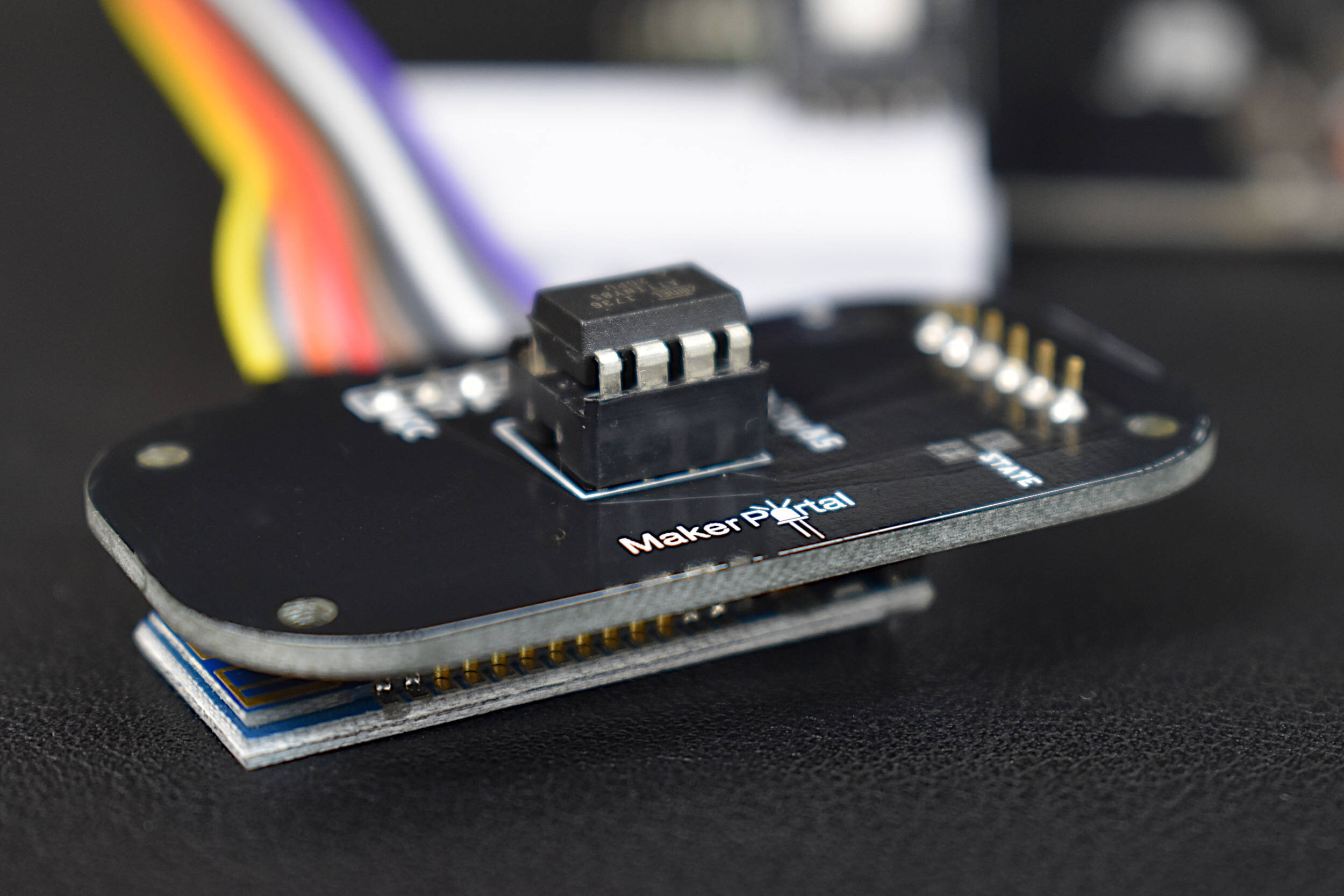
A drawing of the TinyBlueX is given below:

The pinout capabilities of the module are also given below:

Pinout of the TinyBlueX Module
Pins 2,3,7 are general purpose input/output (GPIO) pins. Pins 5/6 are reserved for the BLE module, pin 1 is the ATtiny85 reset pin, and VCC/GND can be used for powering sensors and actuators.
For further reference, the ATtiny85 pinout is also given below:

The TinyBlueX requires a USB to ISP adapter in order to upload code to it. An Arduino Uno board works just fine for this using the Arduino as ISP mode on the Arduino IDE. The complete procedure used to upload code to the TinyBlueX is given in this section. First, the the ATtiny85 must be programmed as an Arduino board using the ATtiny package created by David A. Mellis (here is a link to the package on GitHub). The ATtiny package link must be added to the boards manager in the Arduino IDE:
https://raw.githubusercontent.com/damellis/attiny/ide-1.6.x-boards-manager/package_damellis_attiny_index.json
The following screenshots outline the procedure for adding the ATtiny package to the Arduino IDE:

Step 1: Add ATtiny URL
Add ATtiny Package link [here] from David A. Mellis to File -> Preferences -> Additional Boards Manager URLs

Step 2: Download Package from Boards Manager
Tools -> Board -> Boards Manager -> Type: 'attiny' -> Install
Now the ATtiny Arduino package is installed on the Arduino IDE, which allows user to burn bootloaders and upload code to ATtiny boards. In our case, we will be using the ATtiny85 microcontroller. In the next step, the ‘Arduino as ISP’ code will be uploaded to an Arduino Uno board, which will be required for burning the ATtiny bootloader and uploading code to the TinyBlueX.

Step 3: Upload ArduinoISP Code
File -> Examples -> ArduinoISP. Make sure line 81 is uncommented for the traditional programming using the SPI header on the Uno board. Upload to the Uno board before wiring to the TinyBlueX.
Again, make sure to upload this code to the Uno board before continuing with wiring the TinyBlueX. Then, continue on to the wiring diagram below between the TinyBlueX and Arduino Uno board:

Now, the ATtiny85 bootloader can be burned onto the TinyBlueX using the Arduino Uno board. This can be done using the following procedure:

Step 4: Select ATtiny85 from the Board Menu
On the Arduino IDE: Tools -> Board -> ATtiny Microcontrollers
-> ATtiny25/45/85

Step 5: Verify Board Properties
Processor: ATtiny85, Clock: Internal 8 MHz

Step 6: Change Programmer to ‘Arduino as ISP’
Tools -> Programmer: ‘Arduino as ISP’

Step 7: Burn Bootloader
Tools -> Burn Bootloader
At this point - we have an Arduino and Bluetooth-enabled TinyBlueX board with an 8MHz ATtiny85 microcontroller at the center. In the next section, the wiring will be kept the same and an Arduino program will be uploaded to the TinyBlueX that receives text from an iPhone and transmits the same text back.
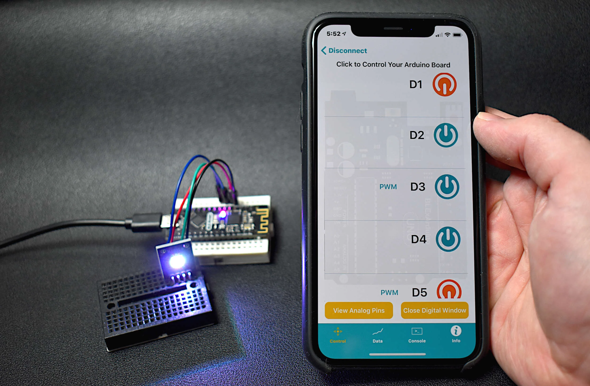
The TinyBlueX can be tested using a simple BLE chat with the BLExAR iOS app. BLExAR is an integrated app that uses Bluetooth Low Energy to communicate with CC254x-based Arduino boards. BLExAR allows iOS users to control/read all available digital and analog pins on the TinyBlueX Arduino board using the CC254x BLE chip contained within the TinyBlueX module.
Keeping the wiring the same as the bootloader burning diagram above, Arduino codes should be uploaded to the TinyBlueX using the traditional Arduino IDE method. The codes are given here and are also available at the project’s GitHub page:

The BLE chat code is also pasted below:
/** BLE Chat between TinyBlueX and BLExAR iOS app
 * -- This code allows the BLExAR iOS app to send text to
 * -- the TinyBlueX combined with the ATtiny85 microcontroller
 * -- and Bluetooth Low Energy module (CC254x chip, also known as:
 * -- HM-10, AT-09, MLT-BT05, JDY-08, etc.)
 *
 *  by Joshua Hrisko, Maker Portal LLC (c) 2021
 *
 */
#include <SoftwareSerial.h>

SoftwareSerial ble_device(0,1); // BLE TX-> ATtiny85 PB0, BLE RX-> ATtiny85 PB1

String tot_val = ""; // storage variable for serial data

void setup() {
  ble_device.begin(9600); // start BLE device
  delay(500); // wait until BLE device starts

  // Once the code is uploaded once, the below can be commented out
  // (the name change only needs to occur once)
  ble_device.println("AT+NAMETinyBlue"); // change device name
  delay(250); // wait for change
  ble_device.println("AT+RESET"); // reset module to enact name change
  delay(500); // wait for reset

}

void loop() {
  char ser_byte = ble_device.read();
  if (int(ser_byte)!=-1){ // make sure it's a valid character
      tot_val+=String(ser_byte); // if the input is over 1 character, this handles that
//      tot_val.trim(); // uncomment to trim any white space (useful for data transfer)
      tot_val.replace(".",""); // the . and @ must be stripped from reading
      tot_val.replace("@",""); // to prevent errors (. and @ should not be used in comm.)
      if (ser_byte=='\n'){ // wait for newline
        delay(50);
        ble_device.println("Received: "+tot_val); // print RX reading
        tot_val = ""; // clear serial input variable
      }
    }
}
Now, if we open the BLExAR app and navigate to the console window, we can type in messages and send them to the TinyBlueX, which will in turn send them back to the iOS device. If a message is received back on the iOS device - then the TinyBlueX Arduino board is working as expected! The following is the output from the BLExAR app after sending several messages to the TinyBlueX from an iPhone:

BLE Chat Between iPhone and TinyBlueX Board
A few notes on the chat: The BLE TX length on the BLExAR is 20 characters, which is why we see the message ‘iPhone Test’ clips the ‘t’ after the TinyBlueX sends ‘Received: iPhone Test’ as two lines. This chat method will be the framework for controlling an RGB LED on the TinyBlueX. We will need to handle the RX parsing in the Arduino code, which will be covered in the next tutorials, along with how to read and transmit sensor data from a DHT22 temperature sensor.
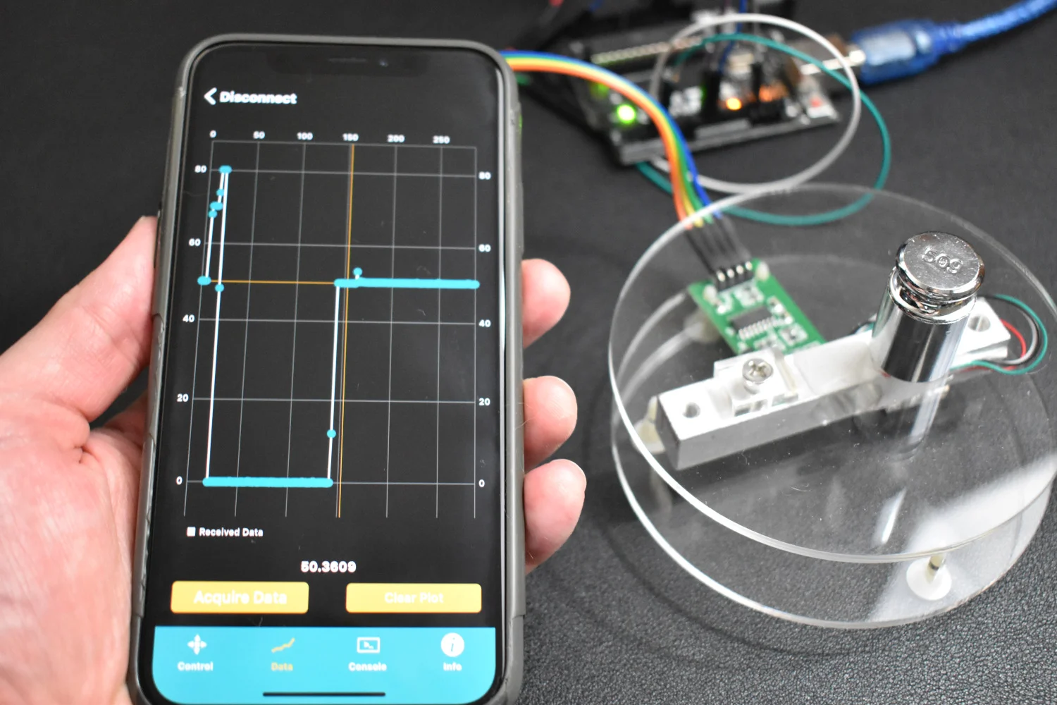
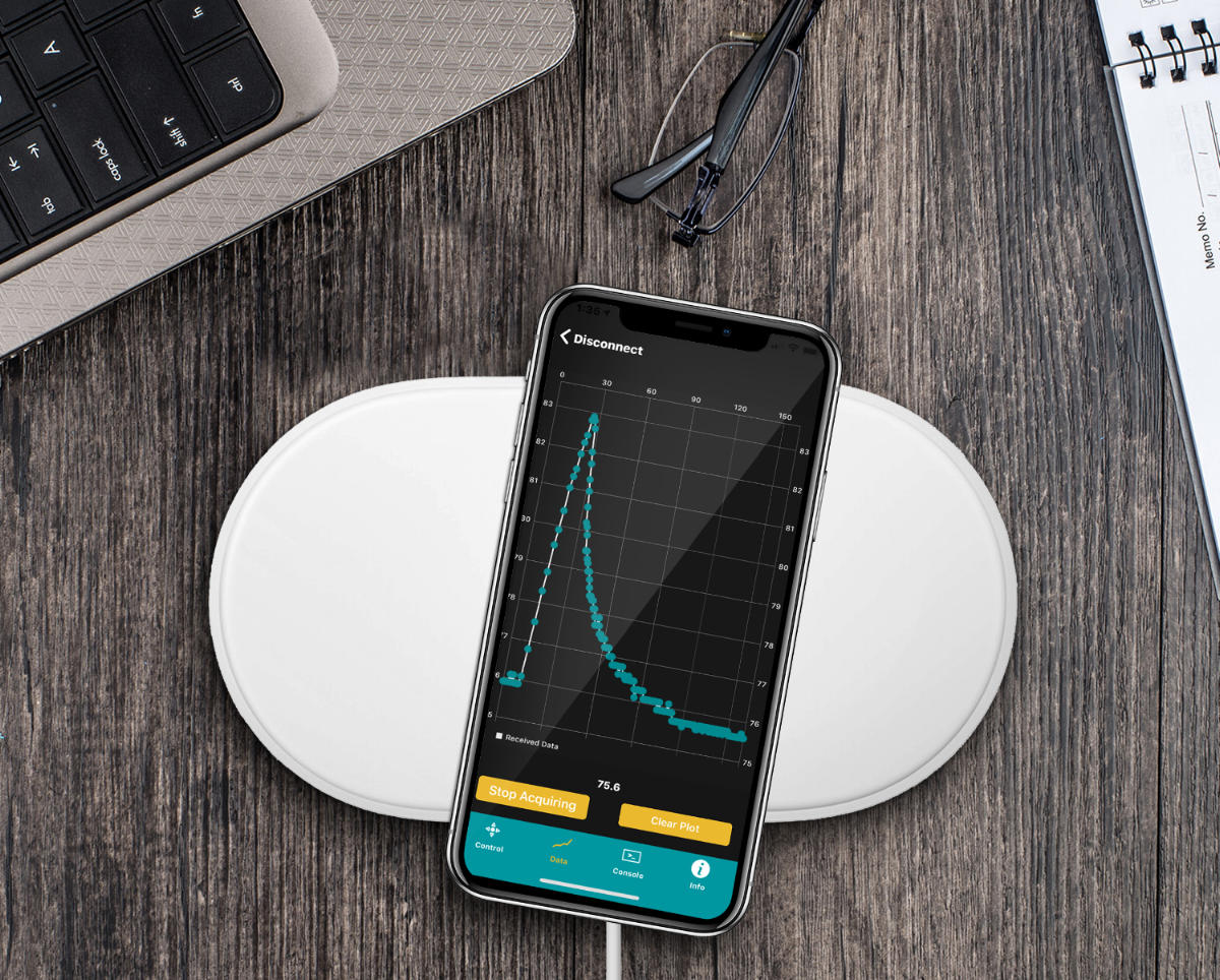
This is the first tutorial in an introductory series focused around the TinyBlueX board. In this tutorial, the focus was on introducing the TinyBlueX board, its functionality, pinout diagram, and a simple Bluetooth Low Energy (BLE) chat between the board and an iOS device via the BLExAR app. The TinyBlueX board is a low-power Bluetooth-enabled Arduino board with an ATtiny85 as its central microcontroller. There is also a CC254x BLE module wired to the ATtiny85, allowing the board to read sensors, control RGB LEDs, and other actuators via Bluetooth. In the next entry into this series, the TinyBlueX will be programmed such that any iOS device using the BLExAR app will be capable of turning an RGB LED on and off. Additionally, an example datalogging application with a DHT22 temperature and humidity sensor will be used to demonstrate the data transmission capabilities of the TinyBlueX board.
See More in Arduino and IoT: